Shawn you got me started with your class on Udemy. Then I stumbled upon this Digi-Key. I like your clear and clean instructions and explanations. Glad I found it.
At some point can you cover clock networks/PLLs? Nearly every FPGA has a huge section of their datasheet discussing clock networks, clock pins, buffers, and a half dozen other things I'm never quite sure how they act together, if I need them, when I would need them, and how I use/interact with them in verilog.
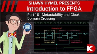
I plan to show how to use the PLL in the IceStick in a future episode, but I don't plan to get into full clock networks. I'll also briefly talk about glitches and metastability.
And also a quick note: the # delay command needs to be terminated with semicolon ; or have a command with semicolon after it. So for example in the code: #10 rst_btn = 0; the #10 line is using the semicolon after the rst_btn=0
I looked at the solution for the challenge verses what was shown in the video for creating test benches and you would be hard pressed to come the final solution with out additional help and resources. The video covers a binary counter and challenge a FSM, I am not sure for a beginner how would solve it on your own.
Am i understand right, the simulation goes Only on the PC and not on the chip itself. Then how we can be sure that the simulator and the real chip will work the same?! Thanks for vids.


This is an amazingly helpful series! Thank you for making the internet a more knowledgeable place.
Shawn you got me started with your class on Udemy. Then I stumbled upon this Digi-Key. I like your clear and clean instructions and explanations. Glad I found it.
Welcome, and thank you--I'm really glad you like my teaching style!
Great info as usual. Thanks Shawn!
Muito Obrigado por democratizar esse conhecimento ❤
At some point can you cover clock networks/PLLs? Nearly every FPGA has a huge section of their datasheet discussing clock networks, clock pins, buffers, and a half dozen other things I'm never quite sure how they act together, if I need them, when I would need them, and how I use/interact with them in verilog.
I plan to show how to use the PLL in the IceStick in a future episode, but I don't plan to get into full clock networks. I'll also briefly talk about glitches and metastability.
And also a quick note:
the # delay command needs to be terminated with semicolon ; or have a command with semicolon after it.
So for example in the code:
#10
rst_btn = 0;
the #10 line is using the semicolon after the rst_btn=0
Ah! Good to know, thank you.
Any pointers for automation of tests ?
How to display the value of parameters and localparamereters in the verilog code in gtkwave?
I looked at the solution for the challenge verses what was shown in the video for creating test benches and you would be hard pressed to come the final solution with out additional help and resources. The video covers a binary counter and challenge a FSM, I am not sure for a beginner how would solve it on your own.
Am i understand right, the simulation goes Only on the PC and not on the chip itself. Then how we can be sure that the simulator and the real chip will work the same?!
Thanks for vids.
To the ones not very familiar with HDLs, I suggest using VHDL instead of Verilog. Much more features, very good structure and easier in simulation