Interesting video, thank you. I listened to your question and paused the video and attempted it myself before watching the rest. I got the correct answers but I didn't go about it your way. I saw the non inverting pin facing a signal with a voltage divider atached to it (You said you shouldn't do it this way but I think you can) 1) If you do this, you get a voltage of (0.75 / (20 + 80)) x 80....= 0.6 OP amp rules say the Inverting pin will also be at 0.6 and 0.6 / 3.3K = Is = 181.81 uA, Is = If, so voltage across Rf = Is x Rf = 8.4, now add the voltage of 0.6 at the inverting pin and you get 9V 2) Your saturation voltage is 10V, 10V across Rf + Rs gives a current through Rf and Rs of 202.02 uA This gives a voltage of 0.66666 at the inverting pin, Op amp rule again, means the Non inverting pin voltage is also 0.666666, Voltage across the variable resistor = 0.666666 and 0.75 - 0.666666 = 0.08333333 across the 20K resistor, 0.08333333 / 20K = 4.1666666 uA through the 20K resistor This same current goes through the variable resistor to ground and so developes the voltage of 0.6666666 This variable resistor has to be..... 0.6666666 V / 4.1666666 uA = 159.99999 K Ohns....
I will say. telling everyone that you will get the wrong answer if you start adding the resistors is wrong. you can find the voltage drop across the 20kohm resistor and subtract it from the source voltage (which requires adding the resistances) to get what you call the Thevenin voltage. This is because we can assume no current goes into the op-amp but instead the voltage does. I only came to this video to remember saturation.
Though this is a solid explanation I honestly think it would help students more if they found the result with the use of kcl. I personally think not only is it good practice for node voltage method but helps you see how both terminals of op amp have same voltage.
There's an exercise that is just like this one on the book I have, this is a much better approach than the way it was shown on some solutionaries online where they get v1 and v2 by KCL and hi-pity-hop they mess around till getting the answer, especially part b). Guess Thevenin is worth knowing
If max Vo (saturated) is +10V and gain is 15, divide 10/15 for max Vin at .666v and toss that with the 20K fixed resistor into a voltage divider calculator and you easily get ~159K ohms for Rx :)
AWESOME EXPLANATION SIR. For inverting mode I think to avoid saturation if same configuration is used but in inverting mode then Vth will assumed to be equal to negative 10 V?
To get voltage at the non-inverting input, why did you not just use ohm's law I=E/R? Which would be .75/100K = .0000075 Amp (7.5uA). Then you measure the voltage drop across the 20K as 20K * 7.5uA = 150mv. So 750mV-150mV = 600mV at the non-inverting input.
Hi Mr. math and science, i am learning how to model in LTspice circuit simulation. things like the "universalopamp2" and the like.. so, this looks like something interesting to simulate.. thanks..:)
Teacher is this video is complete? I mean is this the same you've include it in your website course(same length, same content or is just a part/section of it??? I don't get it on your website says this course last 7 hours but on if you sum all the minutes showed here in TH-cam are less than 2.5hrs, don't misunderstand me I've just want to know if I get more on the paid video course, even tough I'm planning to buy another one from your website, Thanks.
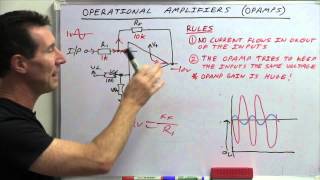
Mr. Prem Anath one terminal of both resistance 20K and Rx(80K) is directly connected and other terminals of both resistance is grounded. That's why 20K and 80 K are in parrallel.
GREAT VIDEO!! one question: Do you know a way to make a ...single op-amp.... with completely independent amplitude and offset adjustments (the gain must go down to zero)? THIS WILL HELP A LOT!!! THANKS MUCH!!!
The answer for (b) is exactly 160k ohms no need to round, the conversion loose digits because of converting to real numbers during own conversions. Normally; 9.Rx=8.(Rx+160k) if you calculate using rational numbers without conversion to real numbers. That gives exactly Rx=160k.
I would have gotten this wrong. At the non-inverting input I see a voltage divider center tapped by a high input impedance. I do not see how the 20k and 80k are in parallel. Can you explain what make it parallel? TIA.
For the calculation of Vth: You take the voltage that the Opamp "sees". Opamp has virtually infinite input impedance, meaning no current goes in... So you can imagine the input side as if it were cut of from the amplifier .. and you literally have a voltage divider. For the calculation of Rth: You need to replace voltage and/or current sources by their internal (ideal) resistance. Note that here V-in is a *voltage* source AND that *ideal* voltage sources have an internal resistance of zero ohms. In the resulting equivalent (Thevenin) circuit the 20k resistance is then connected to ground (through that zero ohms virtual internal resistance) That means that from the +input you see both resistors connected *in parallel* to ground. Edit.. I m quite sure your problem was that you didn't know or didn't remember to replace sources by their internal resistance... That's just a requirement that follows from the Thevenin theorem, because it is a theorem dealing with voltages.
So if you had two resistors connected in series instead of parallel at Vin + we could still use the non-inverting op amp equation as in the previous video?
GOOD AFTERNOON CAN YOU HELP ME SOLVE THIS PROBLEM A force-measuring transducer has an open-circuit output voltage of 95 mV and an output impedance of Ω. To amplify the signal voltage, it is connected to an amplifier with a gain of 10. Estimate the input loading error if the amplifier has an input impedance of (a) 4KΩ or (b) 1 M Ω. Specify values of resistors and for a non-inverting 741 op-amp amplifier with a gain of 10. Find the cutoff frequency and the phase shift for a sinusoidal input voltage with a frequency of 10,000 Hz. PLS IVE SEEN NO VIDEO ON THIS. THANKS I'LL BE WAITING FOR THIS
Then the op amp will act as a differential amplifier and it will subtract the voltages on the + terminal multiplied by the gain from the the voltage on the - terminal of the op amp multiplied by its gain.
What is the function if Rx guys please? It doesn't affect the output so what's its function in the circuit?!! This question is getting me mad and i'm supposed to answer it in my next microelectronics exam...
Hello :-) I have 2 questions, pls answer someone: Can I replace my 2 amp speakers with stronger ones, (bcoz I think they are damaged), will it have some bad affects on amplifier?? And same thing with potentiometers, if I replace them with stronger, from originally 25k-50k to 250k (gain, tone and volume), would be it ok/better ??
Too much BS! Just get the gain and multiply by your voltage devider. Remember your signs if it's none inverting add one to your gain, if it's inverting then minus one on your gain.


I passed my college without really understood this topic. But your explanation is so great and so clear to make me understand.
Interesting video, thank you.
I listened to your question and paused the video and attempted it myself before watching the rest.
I got the correct answers but I didn't go about it your way.
I saw the non inverting pin facing a signal with a voltage divider atached to it (You said you shouldn't do it this way but I think you can)
1) If you do this, you get a voltage of (0.75 / (20 + 80)) x 80....= 0.6
OP amp rules say the Inverting pin will also be at 0.6 and 0.6 / 3.3K = Is = 181.81 uA,
Is = If, so voltage across Rf = Is x Rf = 8.4, now add the voltage of 0.6 at the inverting pin and you get 9V
2) Your saturation voltage is 10V,
10V across Rf + Rs gives a current through Rf and Rs of 202.02 uA
This gives a voltage of 0.66666 at the inverting pin,
Op amp rule again, means the Non inverting pin voltage is also 0.666666,
Voltage across the variable resistor = 0.666666 and 0.75 - 0.666666 = 0.08333333 across the 20K resistor,
0.08333333 / 20K = 4.1666666 uA through the 20K resistor
This same current goes through the variable resistor to ground and so developes the voltage of 0.6666666
This variable resistor has to be..... 0.6666666 V / 4.1666666 uA = 159.99999 K Ohns....
Thank you! so helpful. your channel should get more recognition.
I will say. telling everyone that you will get the wrong answer if you start adding the resistors is wrong. you can find the voltage drop across the 20kohm resistor and subtract it from the source voltage (which requires adding the resistances) to get what you call the Thevenin voltage. This is because we can assume no current goes into the op-amp but instead the voltage does. I only came to this video to remember saturation.
In shona we say uyu murairidzi wemandorokwati meaning this one is a legendary lecturer.
seriously, you are such a great teacher!! more vids please!!
Though this is a solid explanation I honestly think it would help students more if they found the result with the use of kcl. I personally think not only is it good practice for node voltage method but helps you see how both terminals of op amp have same voltage.
Super under rated comment
There's an exercise that is just like this one on the book I have, this is a much better approach than the way it was shown on some solutionaries online where they get v1 and v2 by KCL and hi-pity-hop they mess around till getting the answer, especially part b). Guess Thevenin is worth knowing
Thank you so much sir ,i have an exam next Monday and I'll tell you how it goes ,hopefully I'll get a full mark in this question
thanks a lot sir ,excellent explanation
love this. straight to business
awsome explanation sir.....love from india
What playlist is this in on the mathtutordvd youtube page? I'm trying to find the next video on the subject of op amps.
th-cam.com/play/PLnVYEpTNGNtUaw-eeSzu7pRFGNA7X8G_H.html
Why not just use voltage divider to find the input voltage?
Yeah creating Thevenin equivalents is unnecessary in this example
Thank you. The video is very helpful!
If max Vo (saturated) is +10V and gain is 15, divide 10/15 for max Vin at .666v and toss that with the 20K fixed resistor into a voltage divider calculator and you easily get ~159K ohms for Rx :)
AWESOME EXPLANATION SIR. For inverting mode I think to avoid saturation if same configuration is used but in inverting mode then Vth will assumed to be equal to negative 10 V?
Great explanation
I worked 5 days for find the value of rx for a amp meter
To get voltage at the non-inverting input, why did you not just use ohm's law I=E/R? Which would be .75/100K = .0000075 Amp (7.5uA). Then you measure the voltage drop across the 20K as 20K * 7.5uA = 150mv. So 750mV-150mV = 600mV at the non-inverting input.
Hi Mr. math and science, i am learning how to model in LTspice circuit simulation. things like the "universalopamp2" and the like.. so, this looks like something interesting to simulate.. thanks..:)
Wow, can you please do transfer function review for this circuit
Teacher is this video is complete? I mean is this the same you've include it in your website course(same length, same content or is just a part/section of it??? I don't get it on your website says this course last 7 hours but on if you sum all the minutes showed here in TH-cam are less than 2.5hrs, don't misunderstand me I've just want to know if I get more on the paid video course, even tough I'm planning to buy another one from your website, Thanks.
Hi Sir can you help me understand how the two resistors(20k ohm and 80k ohm) are parallel? I don't see both ends of their nodes connected to the same
Mr. Prem Anath one terminal of both resistance 20K and Rx(80K) is directly connected and other terminals of both resistance is grounded. That's why 20K and 80 K are in parrallel.
Thanks 😊👍🙏💯
GREAT VIDEO!! one question:
Do you know a way to make a ...single op-amp.... with completely independent amplitude and offset adjustments (the gain must go down to zero)?
THIS WILL HELP A LOT!!!
THANKS MUCH!!!
so what about the voltage drop at rth???
Nicely explained sir.
14:44 😂i like this teacher ♡
How can we make more powerful amplifier using 4 opp- Amp in the bridge connection???
I have an exam on this soon...does anyone know great resources for me to prepare
The answer for (b) is exactly 160k ohms no need to round, the conversion loose digits because of converting to real numbers during own conversions. Normally; 9.Rx=8.(Rx+160k) if you calculate using rational numbers without conversion to real numbers. That gives exactly Rx=160k.
How do I calculate Rx if it not given ?
How did you arrive at .111 20:29
I would have gotten this wrong. At the non-inverting input I see a voltage divider center tapped by a high input impedance. I do not see how the 20k and 80k are in parallel. Can you explain what make it parallel? TIA.
It is a voltage divider.
For the calculation of Vth:
You take the voltage that the Opamp "sees". Opamp has virtually infinite input impedance, meaning no current goes in... So you can imagine the input side as if it were cut of from the amplifier .. and you literally have a voltage divider.
For the calculation of Rth:
You need to replace voltage and/or current sources by their internal (ideal) resistance.
Note that here V-in is a *voltage* source AND that *ideal* voltage sources have an internal resistance of zero ohms.
In the resulting equivalent (Thevenin) circuit the 20k resistance is then connected to ground (through that zero ohms virtual internal resistance)
That means that from the +input you see both resistors connected *in parallel* to ground.
Edit.. I m quite sure your problem was that you didn't know or didn't remember to replace sources by their internal resistance... That's just a requirement that follows from the Thevenin theorem, because it is a theorem dealing with voltages.
Thank you alot💙💙🔥
Hello i have a question. Why is there no voltage drop over the resistor in the thevelin equivalent circuit. Great lecture thanks alot.
Because its not connected to any load yet , no current flow = no voltage drop. Regards.
So if you had two resistors connected in series instead of parallel at Vin + we could still use the non-inverting op amp equation as in the previous video?
Yep after finding V thenvin and R thenvin u can proceed.
Yes. Since no current goes into the op amp
thanks, its incredible
can you do some explanation with load resistors
Why did you use 1+(Rf/Rs) for the inverting amplifier bit?? Isn’t it just -(Rf/Rs)
This is a non-inverting amp.
wow nice class
Excellent, thank you.
GOOD AFTERNOON CAN YOU HELP ME SOLVE THIS PROBLEM
A force-measuring transducer has an open-circuit output voltage of 95 mV and an
output impedance of Ω. To amplify the signal voltage, it is connected to an
amplifier with a gain of 10.
Estimate the input loading error if the amplifier has an input impedance of
(a) 4KΩ or
(b) 1 M Ω.
Specify values of resistors and for a non-inverting 741 op-amp amplifier with a gain of
10.
Find the cutoff frequency and the phase shift for a sinusoidal input voltage with a
frequency of 10,000 Hz.
PLS IVE SEEN NO VIDEO ON THIS.
THANKS I'LL BE WAITING FOR THIS
you made it very complicated, there was no point to use Thevenian here
i got question what if given the same circuit but there's an input voltage on the inverting part as well
Then the op amp will act as a differential amplifier and it will subtract the voltages on the + terminal multiplied by the gain from the the voltage on the - terminal of the op amp multiplied by its gain.
Sir I thought the output voltage was supposed to be the product of the difference between the input voltage.
That is a comparator
This subject was a headache back in 1997 at the University for me the professor studied at Japan but lacked explanation skills.
Good
how find from this circuit Vin?
Vth is Vin in this case. 600mV
Nice
thank you so much!!
but if you place 600mv at the inverting input you get 8.962v! why not 9?
What is the function if Rx guys please? It doesn't affect the output so what's its function in the circuit?!! This question is getting me mad and i'm supposed to answer it in my next microelectronics exam...
Rx changes the Vin
I teach electronics as well
Why not use 330 Ohm and 4700 Ohm
Hello :-) I have 2 questions, pls answer someone:
Can I replace my 2 amp speakers with stronger ones, (bcoz I think they are damaged), will it have some bad affects on amplifier??
And same thing with potentiometers, if I replace them with stronger, from originally 25k-50k to 250k (gain, tone and volume), would be it ok/better ??
BTW: Thumbs up and subscribe!
Too much BS!
Just get the gain and multiply by your voltage devider. Remember your signs if it's none inverting add one to your gain, if it's inverting then minus one on your gain.
V th= wrong answer
FIRST EXPLAIN EASY THE BASICS: whats the meaning of inverting ?
Means output will be inverted with respect to input... Or 180 degrees shift
Thank you so much!!!!