Explore Working Applications of 8 Different Op-Amp Circuits - DC To Daylight

ฝัง
- เผยแพร่เมื่อ 12 พ.ค. 2024
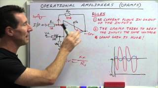
- In this episode, we explore eight different op-amp circuits: the non-inverting amplifier, inverting amplifier, comparator, peak detector, summing amp, differential amp, as well as the clipper and clamper. The objective is to provide working applications for op-amps as a springboard for your own projects, while not spending an excessive amount of time in the world of math bit.ly/3zoT8o1
Engage with the element14 presents team on the element14 Community - suggest builds, find project files and behind the scenes video: bit.ly/3tmdewv
Visit the element14 Community for more great activities and free hardware: bit.ly/3q6YMpu
Tech Spotlights: bit.ly/3qPrDhM
RoadTest and Reviews: bit.ly/3pV5Bux
Project14: bit.ly/31wbnJY
#0:00 Welcome to DC to Daylight
#1:01 Inverting Amplifier
#3:23 Non-Inverting Amplifier
#5:17 Comparator
#7:45 Peak Detector
#10:27 Summing Amplifier
#12:52 Differential Amplifier
#15:15 Clipper Circuit
#16:57 Clamper Circuit
#18:09 Give Your Feedback
#opamp #operationalamplifier #comparator #circuits - วิทยาศาสตร์และเทคโนโลยี


I will keep this episode as my reference for op amps. As usual magnificent. 👏
Most excellent, so nice to have a practical guide to go along with the many theory based ones :)
That is better than any text book!
I love videos like this. Thank you for bringing this to us!
Such a great presentation. You show practical working ciruits with good examples (love the diff opamp substraction noise -- where you created a simple noise source as well!), the theory, the scope it all just makes so much sense and is to the point, so it's easier to reproduce and make actual practical sense. Thanks!
❤❤o😂❤o❤😂❤❤❤❤❤o❤❤😂❤😂❤o❤7❤❤90😢❤😂❤❤o😂
Excellent video, will keep this as reference for op-amp circuits. Thanks!
THIS WAS CRAZY HELPFULL, u back to life some ideas that i got that i thought they were too complicated (for me) or expensive, thank you, love your channel
Thanks Manuel! -Derek
very nice video. shows great examples of how to use common setups for op-amps
very helpful video showing the circuits in operation - thanks for doing it !
Fantastic reference! Thank you 🙌
It's also very important to mention rail-to-rail feature of op amps. TL082 is not a rail-to-rail op amp, so the output is not expected to fully reach Vcc/-Vcc.
Also, it would have been nice to enlist the voltage follower (a.k.a. unity gain amplifier, or isolation amplifier) which has high impedance input.
Very nice video, I also saved it :)
The same applies to 741 as to the rail-to-rail "capability".
Watched it twice and took notes. Thanks Derek!!
Thanks. Glad it was useful. -Derek
Straightforward, I must say. Great example of eliminating common mode noise.
Excellent info. Well done!
Awesome breakdown. Thank you
Excellent video. Thank you sir!
Sir thanks for best video with graphical representation with great interest .You should have been great professor for college students.
Very cool. Thanks!
Awesome video. Thank you.
Thanks a lot sir from India
Thank you so much.🙌❤
HI, Can I ask a question about the differential circuit. I have a DJ mixer that has two opamps for left and right with hot and cold. On both of the left and right signals when I turn up the volume the hot signal is distorted. I am using a sine wave test tone to check and I can see the top of the hot clips, but the cold is ok. The part that is confusing me is that it's the same on the left and right and the only part that is common is the 15v VCC. The original fault was noXLR output and it had fuses on the coldside that had blown. I am researching as much as I can and this mixer does not have a schematic so I am using one that had the same fuses on the cold side as reference. The signal going into this circuit looks to be even on the hot and cold side from the dac.
Love videos with op amps
Great video. Thanks
Awesome video and explanations! It is really good to see the effect of such circuits on the scope, with just a simple sin wave, making things really clear, even for noobs like me!
Awesome. Glad it was useful! -Derek
Excellent!!
NIce vid!! My favourite one is an all-pass phase shifter circuit with an op-amp, using a potentiometer as the phase changer.
Aw. Why didn't I think of that? Next time I suppose. Thanks for the idea! -Derek
10:52 How is the potentiometer hooked up in this Summing Amplifier example? 11:47 You say you have potentiometer hooked up in the other input terminal. Schematic? I see a potentiometer here 5:30. But I'm not sure what to do with with all the other resistors. Complete schematics + capacitors?
Excellent Job
super nice! thx
This is such a handy reference guide. I'm always afraid to play with op amps.
Because I'm a n00b I only discovered yesterday the affects of putting capacitors in series vrs parallel. I feel like that could be an interesting topic of discussion!
Thanks Aaron. In an upcoming video I touch on this a little more. Op amp RC circuits are on the list for sure! -Derek
Just remember that all circuit are just basic versions. E.g. the peak detector needs a feadback path for the negative signal, otherwise it drives the opamp into saturation. You can see that at the scope. The 1n4148 diode is to fast to cause the seen „switch noise“. Just look up for „ideal diode“ to find circuits for that.
Excelent vídeo Thanks
Great work. I would love to see a video of how to use these circuit blocks in real life applications (when , where and how to use each one as part of a circuit that accomplishes some sort of function)
Nice video! Just in time for my analog frontend designing.
Good luck! -Derek
I m from india ...thanku sir your teaching method is very good
I always love to wait your videos..
Thank sir.... ❤️❤️
Thank you Umesh! -Derek
Nice video, thanks :)
Thanks for your effort and nice method
Could you please make a video about rail -to rail op amp
Nice! Very nice!
I'm from DRc I like the way u are explaining things
great video. Btw, what bread board brand do you buy? Which one has the best inside connectors?
Amazing
top quality video
Thank you so much
You're most welcome
Thanks again for a great, to the point video. A few questions I would like to ask: Which single supply opAmp would you recommend for hobbyists to use in new designs? For low-ish frequencies, say under 100 kHz and voltages in 10s to 100s mV. For use as a comparator?
What is the typical value of the bypass capacitors? Or, what should one consider when choosing the value.
That's a question that doesn't have a single answer. Almost any opamp can work with a single supply if you create a virtual ground at half the supply voltage, Using a TL431A to create that mid-point voltage works well for low current applications and they are really cheap.
Anyway, you need to decide whether you want to use an opamp with digital circuits like an Arduino, or with analogue circuits like audio use. For digital interfacing, you'll get the best voltage swing from a 5V (or 3.3V) supply by using a rail-to-rail opamp, which means a CMOS type these days. I like the MCP602, but there are many to choose from.
For audio use, you can get really low noise, high-specification audio opamps, but they are expensive. For the hobbyist, I'd recommend the LM4562 which is about twice the price of the NE5532, but with significantly better performance.
If there's no specific requirement, you might as well use the LM358. It's nowhere near as good as more modern, specialised opamps, but it's dirt cheap and there are thousands of circuits designed around it.
Finally, I'd use a comparator for a comparator, not an opamp. There are no problems with lock-up, phase inversion, limited common mode range, etc. The LM393 works in all but the most specialised comparator circuits, and it's also cheap.
As for the decoupling capacitors, you just want something that provides a low impedance path between the supply rails and ground, especially for high frequencies, so the value is not critical. You just want something with low self-inductance mounted close to the supply pins. Most of the time a 100nF capacitor, ceramic or better will work fine.
@@RexxSchneider Thanks so much for your detailed reply. As you mentioned, there are so many to choose from, and unless one uses them extensively, it can be difficult to find a starting point.
And your comment about using a comparator is well taken 👍
Thank you, this is a good refresher for me. Now back to Green Acres.
I hear it's the place to be. -Derek
Sir . Did you ever experienced there is phase lag in output when inverting and non inverting are fed with same ac signal , thanks
I have question with invertina amplifier much more powerfull output goes to input and can it also affect the signal source... if it very weak? it just have to pass couple resistors
Great video! May I suggest adding a link to a pdf with the schematic images in the description? It would be a great resource for all of us! Myself included.
Hi ElectroRestore. I am currently working on getting the schematics exported and uploaded to the community / links. Thanks! -Derek
Are you using scope probes to feed the input signals with a signal generator? In the other opamp video of yours, you use a solderable BNC connector, you can see the center lead of the BNC connector going the breadboard, but the shield/GND lead is not clearly visible. It seems to go to GND, but it's not clear if it is 50 ohm terminated or not.
Can you give a clearer picture?
Well explained sir
Thank you! -Derek
8:11 it is an "ideal diode" due to the feedback loop. 😊
Great video. I too love the differential amplifier circuit. What op amp would you recommend for use at HF radio frequencies, such as 3 MHz to 30 MHz?
Hi Al. I have to admit I've never used a specialized op amp for RF in the ham bands. I know they do make them, but I've always felt more comfortable using discrete topologies for RF amplification. There are monolithic devices from manufacturers like mini-circuits, but the internal topology is very different from the traditional transconductance-VAS-pushpull op amp. Those are more like a darlington transistor if I recall correctly. -Derek
Hi can you make video on how one port and two port network synthesis applied practically on designing ckts like filters and amplifiers, thank you.
What caps are you using? 0.1uF ceramic caps?
Nice 🎉
Can I run this type of op-amp at hf frequencies for zero crossing counts ?
Super
Very good sir
Thanks! -Derek
This is great and I like a bit a maths there. But what value are the caps, is it any value ceramic cap or?
Edit: coupling capicitor values are recomended in the opamp datasheet!
One detail on the diff amp common mode rejection, is more dependent of how well the resistors are matched than the intrinsic
common mode rejection of the op amp. Depending on the required rejection it may be desirable match resistor values if you
have a bag of 100 resistors depending on the CMR desired and your meter it's possible to improve performance by taking
this extra step.
Thank you for the additional information. This would be a fun exercise to undertake as an experiment... I've never done so, and it would be useful to quantify. Great tip! -Derek
Nice! 🍾🥂
Thanks! -derek
All is good all is well but as an amateur my area and need is a single side p.s I wish I find all of these ccts similar to my requirements though I dare not to ask u do that cos it's a bother ....Thx any way.
Wht about an error amp, so how does the work. Could be missi g some thing. T
It appears that there is a bit of overshoot at the beginning of the clipped voltage region in the clipper circuit. Is this typical of this configuration?
Not enough bandwidth. The opamp needs some time to recover from the saturation, as it is used as a comparator here.
Cool. What model Rigol are you using?
Hey Jim! 1054Z my friend.
I have a bachelors in EE from UC Irvine and they never taught it like this!
Thank you very much for the feedback. Good to know I’m on the right track in making these applications/demos useful. -Derek
コンパレーターで、どちらの入力が電圧が高いかをLEDで表現したのには、感動しました。
Hey Doc, what circuit is needed to produce 1.21 GW of electricity? 😊
Hi Meriç, Just a really, reaaaaaally big voltage difference! -Derek🌩
Several cats, a vinyl couch, and a very dry day should do it.....
You might want to point out the effect that resistor tolerances have on observed gain - looks like you're using 1% tolerance resistors, so not much of an issue, but with 10% tolerance ones you could see a much bigger difference (up to 20%, I think) in the observed gain if the resistors happen to be at opposite ends of the tolerance range.
Hi RayDT, that’s an excellent topic to add to the list! This was a kind of crash course in op amps, but I’ve been thinking about a component tolerance video as it applies to passives as well as active semiconductor components. Thanks for the valuable feedback! -derek
@@AmRadPodcast When you do, don't forget to point out the additional color band on 1% tolerance resistors, that can sometimes confuse less-experienced people.
At 8:51 the diode is actually connected from pin 6 to the inverting input. Not the non-inverting input.
great video ffir anyone serious about analog electronics
If I go to college and enroll Electronics associated (2 years ) United Stated here, May will have the chance for job? I don't think I will make it Electric Engineer, EE is so hard for my capabilities but I like electronics wondering at my 40's if there's a bad or good idea? As you guess I am not a burnt in the US.
Is that a working flux capacitor and when's the video on how to make that one coming out? 🤔😄
Just here to window shop in the hopes that one day when I'm not lazy I'll get around to doing all the stuff with this that I've planned on doing 😂
That is a Flux Capacitor...and your lab won't be complete until you have one in the background too.
Here ya go! : th-cam.com/video/oMLD13UdEsQ/w-d-xo.html
A question someone might answer: if I increase the 5.6K feedback resistor on 13:19 to a value of say 11K, then the gain increases as well, right?
Any time we increase the feedback resistor, the gain also increases?
Thank you to whoever will answer this. I'm at the beginning to understand amplification.
That is correct. If you increase the feedback resistor, then the gain increases.. I find it helpful to look at situations in this way: What happens when I set this value to an extremely large value, then what happens if I set it to some really small value. If you look at the gain formula, if we play with R2 this way, you can see how it affects Vout and gain. An R2 value greater than R1 and the absolute value of Vout increases.. If R2 is less than R1, then we end up with a smaller Vout, or an attenuator. (note there can be stability issues when using an op amp as an attenuator). Hope that helps! -Derek
@@AmRadPodcast, thank you so much, Derek! 😃
I have a modern 1993 Yamaha integrated amp with THD of 0.001% and it doesn't play as nice as my 1970 vintage Sony amp, which has a THD of 1%. A friend told me to increase the feedback resistor to a higher value, so the sound would be in a more "2nd harmonics" character. The problem is "how much" higher the 22k FB resistor in the Yamaha amp can be increased without oscillating. I don't have an oscilloscope or spectrum analyzer to see how the harmonics peaks follow after the 1k Hz fundamental.
Do you think I can double the 22K FB resistor to 47k ohms?
Thank you immensely.
❤❤❤❤❤❤
What is vcc value and vee value sir....
If using a bipolar supply and if the input signal reference is at GND as in the examples... as long as Vcc and Vee are greater than (a volt or two) the input signal swing, it doesn't matter what the rail voltages are; Of course you still need to stay within the max supply voltage of the datasheet. In the example, I believe I had Vcc set to +10V and Vee at -10V. -Derek
When I saw a diode in the peak detector I started thinking and it finally hit me why the fuck an op amp oscillates when it drives a MOSFET (capacitive load). None of that Aol, bodyplot and phase angle shit, simply put the MOSFETs gate capacitance is driving the feedback loop, that's it, pure simplicity!
Strange that you didn't show the schematic for the clamping circuit so essential for TV.
I made an error, and left it off! Schematics will be uploaded to the community links soon. Apologies for the mistake! -Derek
Which configuration has more distortion? Inverting amplifier of non inverting ?
Good question, and a great topic to bring over to the community forum. There is a difference in noise performance which depends on resistor values, and ‘noise gain’ between non-inverting and inverting config. Not a big deal in audio stuff. If we’re talking non-linearity induced distortion, then the non-inverting is slightly worse. Distortion from common mode input voltage is dependent upon signal amplitude and CMRR for non inverting. For inverting this is basically zero.
Of course underlying non linearity exists equally for both cases! -Derek
@@AmRadPodcast thank you for answering my question 🤓
I like what you're doing here but it's a disserve to avoid mentioning that op-amps aren't meant to be used as comparators. A comparator IC is also cheaper.
probably should have used a TL schematic
Would have liked to see the drawn circuit of the clamper. A picture is worth a 1000 words.
I made an error, and left it off! Schematics will be uploaded to the community links soon. Apologies for the mistake! -Derek
Where is the clamper circuit schematic? The last one was the least?
I made an error, and left it off! Schematics will be uploaded to the community links soon. Apologies for the mistake! -Derek
No clamper schematic ? ... or did I miss it ? 🤔
I made an error, and left it off! Schematics will be uploaded to the community links soon. Apologies for the mistake! -Derek
You forgot to show us the log, anti-log and integrator amplifiers. Ant the clamper doesn't have a basic schematic.
To the deviation of measured calculated voltages:
Did you use 0% resistors, or the more common +-5..10% ones?
You rarely have exact values w/o adjustable parts. High precision devices contain multiple adjustment points.
BTW, you are just 1.2% away from theory. A lot of measurement devices aren’t more precise, especially the cheap ones for hobbyist.
Hello Germany. In all demo circuits, I used 1% to 5% tolerance resistors. This was good enough to show the general operation and how to get there from the formulas. Of course when designing circuits, one needs to take a look at what the required specifications are, as well as extremes in temperature and tolerance stackup, and how this would affect performance. -Derek
You lost me at 1:13 "Feeding output back to the non-inverting input". What did I miss?
You didn`t miss anything. You caught one of his many bloopers.
This guy looks like Noodles from The Offspring.
I'll take that as a compliment.. I guess? -Derek
@@AmRadPodcast Haha...sure!
🤵🎙👍
mine just got thermal shutdown
Why use a 741 when a TL081 is so much faster ?
Oops. My bad. Your circuit diagram says 741 but the breadboard is using a TL072. Sorry about that.
Just constructive criticism, first thank you for the video it's great. But you say OK like it is a habit. I don't want to even try and count the times you say OK. But it's not really OK, because while it is OK in a live lecture this ain't that. And the camera you used to record this is just not going respond. And even if the camera does respond, I can't respond to my monitor. I mean I can, but you are not going to stop the lecture and answer my question. And that's why we say OK ... to stop the live lecture and make sure nobody got lost. To ask someone "OK?" rhetorically is just asking for frustration. Trust me ... drop this inflection and you will only improve. Again ... thanks for the video it's great! (and please don't shoot the messenger) 😆
Haze, OK. I think this is the best comment I have ever received. OK, it is a habit... OK, a habit I picked up from one of my electronics professors. OK? Seriously though... I did notice it when I was editing, and it was a bit annoying. And I had three options: 1. Re-record everything, 2. Edit and put jump cuts every time I said it, 3. Let it fly. I chose to let it fly - looking back, maybe it would have been less annoying to go with option 2!
In any event, I sincerely appreciate the constructive criticism, as I'm always trying to improve. There may be a few 'OK' videos in the pipeline to flush out, but there will be less in the future. This is great feedback!!!
Now, have a good day, OK? -Derek
Wow, you've got a flux capacitor on your test equipment shelf. Is it a proper one from Farnell or Mouser or a knock-off from eBay? Please don't take chances with your time travelling safety to an eBay cloned part.
That barely audible background electronic tune is driving me crazy. Are you an engineer? I don't think so, because if you were you would understand the impact of that to most engineers.
Sorry you found it bothersome. I need that music, or my engineering functions cease.
~ nice 🥰😎💋💔👄
!
Agree!
Same music as the FiveThirtyEight politics podcast?
I'm gonna have to get the element14 band together and record a new jam! -Derek
Complete confusion at 16:01 to 16:11 as to which is the inverting and noninverting terminal. The schematic shows the 10K resistor and input into the inverting terminal whereas pin 2 is being described as the noninverting terminal (which it isn't). The anode of the diode schematically is fed into the inverting terminal which, in the narrative, is described as being the noninverting terminal (which is isn't). Element 14 sucks. Videos are convoluted, put together in a lazy and reckless fashion. What a shame.
Your resistor not 100% accurate