Hi everyone - It's come to my attention that there has been someone masquerading as myself, responding to some comments here with a link to a Telegram chat to win a prize from me. THIS IS A SCAM, I am not holding a contest, nor do I have a Telegram account. PLEASE DO NOT RESPOND TO THESE MESSAGES!! It's happening on a lot of my videos, I'm taking steps to remove them manually, but as I have 162 videos, it will take some time. If you do run across a suspicious comment, I would appreciate you letting me know at info@dronebotworkshop.com. Thanks! Bill (The real one!)
Thanks for posting this. I got the "prize" response, but I was pretty ssure it was a scam. Nobody offers prizes to somebody who never joined the competition unless they are expecting to get something out of it. Did you ever hear the upshot from anybody biting at the bait?
Sorry for taking SO long to get another video out, as many of you are aware, we had an ice storm last month that cut my power off for 5 days, and dropped a tree onto my house and another one onto my car. So lots of interruptions while we got that sorted out, and it delayed me from working in the workshop. The tree is off the house now, and I have a rental while the car is being repaired, so I should have another one out shortly. Hope you enjoy this one! Bill
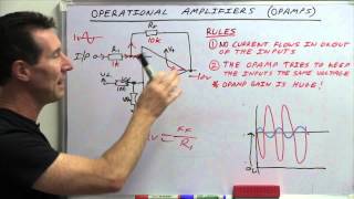
Good day, Mr. Bill, with regards to the non-inverting amplifier, the actual formula is (1 + RF/RD) * VIN, so the actual amplifier gain when using 1k ohms as RF and 1k ohms as RD is actually 2, which explains why the output sine wave is bigger.
Oh my God, thank you for this. I was getting confused seeing why the output is bigger and i learned from other channel that the gain has +1 into it. Bravo, sir
You're like the Bob Ross of Electronics Design. I took a course in analog electronics and spent a lot of time around the theory of Op Amps, but never really got taught about some of their more practical applications. This video was great at keeping things simple, to the point, and wonderful demonstrations to accompany each example. I've liked your videos for a long time, keep up the awesome work!
I have watched numerous explanations of operational amplifiers and this is the best. I really appreciate the documentation you make available. It makes it much easier to actually replicate your demonstrations, trying to follow along with a video is much too frustrating. Thank you for your commitment to teaching others.
The usual high standards that we've learned to expect! Great video, with flawless production. Sorry to hear about the devastating ice storm. It's remarkable that you could *still* produce this video. Best wishes for a speedy "recovery", Bill!
Bill, I'm very sorry to hear about the ice storm and the damage it did to your vehicle. I'm glad you are ok! This was another wonderful video. Thank you for addressing op amps, a challenging subject. You made them a lot more approachable. Thank you also for noting that the formulas for gain are estimations and explaining why (the mention of not including impedances in the formulas). This video is going to help so many people better understand this subject.
You just made me feel really old as I remember when the 741 Opp Amp was released 1968. They were a hassle to design circuits for as they required two power supplies, both a positive and negative with a shared ground. The LM324 (1974) was so much easier to use with its single sided supply.
Maaybe as old as me. I used two 741 op amps in the early '70's to build an electronic théremin, with two capacitive plates for control of tone and volume through respective variable, high frequency oscillators and superhetherodine amplifiers whose residual frecuency, in one of them, was rectified and converted into gain control for the other's audio amplifier.
Greetings. The crkt you have at about 39 minutes, is used on B-1B aircraft. I added a small cap from the opamp output to the common emitter. This allowed a small amount of current (few mA) to flow during the opamp swing between one BE to the other BE transition. It greatly reduced "noise" and reduced the output impedance passing thru open circute etc
I've been a long time viewer but extremely infrequent commenter. I just wanted to say that I truly and sincerely appreciate your videos. I very much appreciate your clear even comprehensible tone and explanations. I truly appreciate what a valuable tool your videos are and how much value they have brought to my project. Thank you very much
Any new student starting Electrical Engineering should watch your videos before going to class. Understanding the principles you put forth would help when the student is presented with circuit analysis problems from a dry as bones professor. I speak from personal experience from 30 years ago.
Sorry for the trouble you've had with the Ice storm, I can relate (more or less...) We've had a really heavy Hail storm around our place that caused a huge roof leak... all fixed now ! And really happy to watch your videos once again, always something informative there. Keep up the great work (and yes it takes Work !), and courage !
Best electronics video of all time. All different uses of an op amp including low pass and high pass filters, ...that was unexpected. I wanted to learn about op amps and active crossover circuits and this video killed many birds in one shot.
Fantastic video as always. I'm sure all your viewers hope all that storm damage is fixed as soon as possible. Picturing the storm damage in my mind led to my imagining how you may have dealt with such a testing situation. What came to mind was an incredibly calm and serene and methodical step by step resolution to all the problems. Perhaps one day you could share the story in more detail? How the interactions with the relevant parties went etc. I can only imagine your methods of dealing with this situation would be a lesson to most of the rest of us viewers too. I know I wouldn't have been calm and methodical if a tree had landed on my house and another one on my car too! I can't imagine you getting angry or losing the plot at all!
Yeah I noticed your absence! Glad to see you're back and that everything gets sorted out. Very informative video and a nice recap of things that I almost had forgotten.
I’ve got to take the prerequisite class to this video. This is very obviously a super informative video. I’ve been learning a lot from this channel. There are just too many concepts and terms I haven’t learned yet. This one will go in the watch later folder.
You are the best youtuber at tech side when it comes to presenting the content who is not just hurry to present something in a rash (Hope I am correct ). Excellent !!!!!!
Minor point, but an offset voltage in the range 1-10mV is the typical offset at the _input,_ not the output. Others have commented on other relevant points. But a very well presented tutorial. Many thanks.
Well i must say i am very impressed by this tutorial. I think probably the best and easy understanding video i have seen in a very long time, and i´ve seen a lot of tutorials but they are so over-mathematical and complicated. You are a very inspiring person for both young and old folks who are new to micro computing and small electronic hobbys. I have recantly diving into the arduino and rpi pico djungle of projects and try to sort all fun and facts in my head cause it´s a lot to take in.
22:37 I want to offer a correction to the gain formula here. Inverting does follow the -Rf/Ri but the noninverting gain follows 1+Rf/Ri, so for setting Rf and Ri equal, the gain 2 which better matches your oscilloscope readout. Otherwise very informative video and of the op-amps, as I work with 5V sources a lot, I go by the MCP6022 almost religiously, using a virtual ground set at 2.5V for sinusoidal operations
Good eyes! Yes, the gain should be (1+RF/RD) using the notation presented. The scope shot did show that the output was in phase and the amplitude of the output was higher than the input amplitude. With RF=RD=1k, the gain should be 2. However, it seemed that the gain was higher than 2 since the scope channels were at 50mV/div for Channel 1 and 500mV/div for Channel 2.
@@Vahe.Caliskan i couldn't see both channel settings but they were off by a factor of 10, which I assumed was likely different probes that didn't have the proper scaling since some use 10x and others use 1x
Glad the 'commenters' saw that, it was a glaring error, it might not make a difference at 'higher' gains, (I.e. A gain of 101 not 100, doesn't give a big error as a gain of let's say 11 instead of 10).
Mr work shop thank you for sharing your knowledge..I am from Jamaica and I found a sudden interest in electronics engineering since September last year. I am will to accept all the help I can get.. again thank you and many blessings to everyone on your channel
Your non inverting amplifier with the 2 equal resistors actually has a gain of 2 because the output is divided by 2 and voltage at the inverting input matches that at the non inverting. The gain formula for this configuration is 1 + (Rf / Rd)
You know.. for $0.10 you could get a CH32V003. It's a 32-bit 48Mhz RISC-V2A processor with 2KB SRAM and 16KB Flash... 10 cents in quantities of 50 for the 8-pin variant. It actually costs more in shipping than it costs for the device... *and it comes with a built-in Op-Amp* :) Analog op-amp exposed right to the pins (with a bit of configuration). Single-side supply, but still useful. Doubt the specs are particularly impressive, but whatever. So, you could buy a 10-cent op-amp for your project... and it comes with an MCU for, you know... whatever. :) Crazy world we live in now. Oh, and thanks for the refresher course. I wanted to try out this integrated op-amp... figured I should start with the basics.
Very good video, excellent explanation, I myself used op-amp 741 to build a triggering circuit for Silicon Controlled Rectifier. to control DC motor speed.
The most critical point you have made was about the amplification range that it is limited to power supply limit (rail-to-rail). 99% of the videos are misleading, present like op-amps could amplify to the moon. Thanks a bunch.
Very good lesson Bill! I needed a refresher. I am working in NBA circuit to take a 0 -5 vdc control and set it up to run several independent motor controllers. My 1st thought was to feed the single control voltage to several unity gain op amps so that each one could then be the control input to its corresponding controller and track properly the changes of the input voltage. The 324 should do the trick.
i just made my first amplifier that actually sounds good with an op amp. i used LM358 for it. when i turn the gain up high enough, it even picks up radio signals lol, so i totally see why audio equipment is always in faraday cages. for the dual supply i just used the other side of the LM358 with another NPN transistor and a voltage divider to provide my common ground.
For inverting and non-inverting amplifiers, the voltage gain AV should not have the Vin term as a multiplier since AV=Vout/Vin. So AV=-RF/Rin for the inverting amplifier and AV=(1+RF/RD) for the non-inverting amplifier. What is shown is actually the output voltage Vout. The extra 1 term in AV for the non-inverting amplifier has already been pointed out in a previous comment.
Very usefull, thanks. Regarding Rd and Rf resistors in inverting and non inverting amp, nobody ever tells us about the range of resistors. For example you used 1K for both but what about 5.6K for both or 10K, or 47K. It is about ratio but I have seen it doesn't work the same if I change the values although it is the same ratio and I spend hours of trial and error without understanding why.
Only partway through but it’s excellent so far as usual. I would like to offer a few corrections from my hobbyist experience building guitar effect pedals: 1. Op amps like NE5532, TL072, etc, do not *require* dual power supplies - they are commonly used in 9V single-supply designs. When used with single supply, however, they need a bias voltage (usually Vcc/2) so that an ac signal can swing positive and negative, and then need to be ac-coupled (typically with 100n-220n film caps) as a result of the bias voltage. LM358 and LM324 are special “single supply” op amps because their output voltage can swing all the way to the negative rail - like half of a rail to rail op amp. That means when powered by a single supply, they can handle input and output voltages all the way down to ground (positive voltages are still limited to around Vcc-2). 2. For an inverting op amp, the effective input impedance becomes R(in) - so by using 1K resistors for an inverting op amp, you’re basically wasting the lovely high impedance of the op amp. (IIRC this happens because R(in) winds up in parallel with the op amp’s inherent input impedance, but don’t hold me to that.) In my experience, you typically see resistor values of 10k-100k for inverting op amps, and even then they are often preceded by an emitter follower or non-inverting buffer to improve the input impedance. 3. The slope of a one-pole filter is -6dB/Oct (not -3dB).
All good comments, but a reply to your point 3. -3dB is the _voltage_ roll off, which Bill likely was talking about. -6dB is the _power_ roll off (power is proportional to voltage squared). 😊
@@BillySugger1965 peddlereffects is correct. The voltage roll off of a first order low pass filter is 6dB per octave (=20dB per decade). You have the power & voltage terms transposed. A 3dB loss in power equals half power. A 6dB loss in voltage equals half voltage.
An extremely important concept, arguably *_the_* single most important concept, is that of the "virtual short circuit" between the inverting and non-inverting inputs. When an op amp is operated closed loop (with feedback) it acts to keep the voltage difference between the two inputs at zero. With real op amps the voltage won't be exactly zero because of finite gain, finite bandwidth and input offset voltage, but it will be very close. Without understanding this, the feedback networks used to determine the behavior of the circuit make no sense. For example, the inverting amp with a gain of -1, as shown at about 20:00 The NII is connected to "zero volts" ("ground'). That means that when the loop is closed with feedback, the inverting input will also be at zero volts. The current from the input source through the 1k resistor (again as shown in the video) will be 1 mA per volt. Let's say we apply +0.5 volts, so we have a current of 0.5 mA flowing toward the input pin (conventional current, flowing from positive to negative). It can't flow into the input pin because of the high impedance of that pin, so where does it go? It MUST go through the feedback resistor. If we have 0 V at the input pin and a 1 k feedback resistor from input to output and that resistor has a current of 0.5 mA through it, the voltage drop across it must be 0.5 V with the input-pin end at zero. The output pin must therefore be negative 0.5 volts. The gain of the circuit is therefore minus one. If we used a 10 k feedback resistor, it would still have 0.5 mA through it, flowing in the same direction. The output would have to go to -5.0 V to allow that current to flow. +0.5 V in, -5.0 V out - a gain of -5.
Thanks for the content. I have a BUGBOOK on op amps by Howard Berlin in my library. I just looked, it has a first printing date of 1977. I’ve had it since then. For you younger viewers we used real books before the evolution of the internet.
Please could you zoom out a bit, your hand actions are important when you are giving your lectures, and I think on previous videos itt shows how good an orator you are.
Not sure if someone pointed this out already, but non-inverting gain is 1+rf/rd so your gain would be 2 where both resistors are 1k. (which it showed on the oscilloscope)
Yes, good catch, some of the top rated comments here pointed that out. I dont think Bill responds to a lot of comments, but to be fair his vids have a tone of comments.
At 4:56 you stated, "...and so our output will go negative. Again, the amplitude of the output will depend on the amount of difference between the two inputs". Um. I do not think that's true because, when you stated this in the video, there was no feedback to the inverting input so any difference between the inputs would cause the output to go all the way to saturation (high/+VCC or low/-VCC). Am I misunderstanding what you were trying to say?
how timely, my "Design with Operational Amplifiers and analog Intergrated Circuits" book by Segio Franco 1988 just arrived this morning! Great lecture and experiments. Sorry to hear about your disaster.
Hello, Could you elaborate exactly what more do you gain on using this op amp light switch circuit over a simple LDR voltage divider with a transistor ( or two ) ?


Hi everyone - It's come to my attention that there has been someone masquerading as myself, responding to some comments here with a link to a Telegram chat to win a prize from me. THIS IS A SCAM, I am not holding a contest, nor do I have a Telegram account. PLEASE DO NOT RESPOND TO THESE MESSAGES!!
It's happening on a lot of my videos, I'm taking steps to remove them manually, but as I have 162 videos, it will take some time. If you do run across a suspicious comment, I would appreciate you letting me know at info@dronebotworkshop.com.
Thanks!
Bill (The real one!)
Yep, just got one and reported it.
Thanks for posting this. I got the "prize" response, but I was pretty ssure it was a scam. Nobody offers prizes to somebody who never joined the competition unless they are expecting to get something out of it. Did you ever hear the upshot from anybody biting at the bait?
Ok Sir
Give Telegram a try though
Sorry for taking SO long to get another video out, as many of you are aware, we had an ice storm last month that cut my power off for 5 days, and dropped a tree onto my house and another one onto my car. So lots of interruptions while we got that sorted out, and it delayed me from working in the workshop. The tree is off the house now, and I have a rental while the car is being repaired, so I should have another one out shortly. Hope you enjoy this one!
Bill
Glad you are safe... Mother Nature can really show who's boss. Thanks for the update and the new tutorial.
Sorry to hear that 😢
Glad you sorted out.
Wow! Glad to see you are safe! As usual, an excellent video.
Hi Bill, Hope you sort everything out soon. Chin up. Cheers Jase :)
Your videos are of the highest quality! You obviously put a lot of time and effort into making them, and it is greatly appreciated.
This deserves appreciation. One of the best explanation of Op-Amps and demonstrations. Thank you very much.
Good day, Mr. Bill, with regards to the non-inverting amplifier, the actual formula is (1 + RF/RD) * VIN, so the actual amplifier gain when using 1k ohms as RF and 1k ohms as RD is actually 2, which explains why the output sine wave is bigger.
Oh my God, thank you for this. I was getting confused seeing why the output is bigger and i learned from other channel that the gain has +1 into it.
Bravo, sir
You're like the Bob Ross of Electronics Design. I took a course in analog electronics and spent a lot of time around the theory of Op Amps, but never really got taught about some of their more practical applications. This video was great at keeping things simple, to the point, and wonderful demonstrations to accompany each example. I've liked your videos for a long time, keep up the awesome work!
I have watched numerous explanations of operational amplifiers and this is the best. I really appreciate the documentation you make available. It makes it much easier to actually replicate your demonstrations, trying to follow along with a video is much too frustrating. Thank you for your commitment to teaching others.
The usual high standards that we've learned to expect! Great video, with flawless production.
Sorry to hear about the devastating ice storm. It's remarkable that you could *still* produce this video. Best wishes for a speedy "recovery", Bill!
Bill,
I'm very sorry to hear about the ice storm and the damage it did to your vehicle. I'm glad you are ok! This was another wonderful video. Thank you for addressing op amps, a challenging subject. You made them a lot more approachable. Thank you also for noting that the formulas for gain are estimations and explaining why (the mention of not including impedances in the formulas). This video is going to help so many people better understand this subject.
You just made me feel really old as I remember when the 741 Opp Amp was released 1968. They were a hassle to design circuits for as they required two power supplies, both a positive and negative with a shared ground. The LM324 (1974) was so much easier to use with its single sided supply.
Maaybe as old as me. I used two 741 op amps in the early '70's to build an electronic théremin, with two capacitive plates for control of tone and volume through respective variable, high frequency oscillators and superhetherodine amplifiers whose residual frecuency, in one of them, was rectified and converted into gain control for the other's audio amplifier.
Greetings. The crkt you have at about 39 minutes, is used on B-1B aircraft. I added a small cap from the opamp output to the common emitter. This allowed a small amount of current (few mA) to flow during the opamp swing between one BE to the other BE transition. It greatly reduced "noise" and reduced the output impedance passing thru open circute etc
I've been a long time viewer but extremely infrequent commenter. I just wanted to say that I truly and sincerely appreciate your videos. I very much appreciate your clear even comprehensible tone and explanations. I truly appreciate what a valuable tool your videos are and how much value they have brought to my project. Thank you very much
Any new student starting Electrical Engineering should watch your videos before going to class. Understanding the principles you put forth would help when the student is presented with circuit analysis problems from a dry as bones professor. I speak from personal experience from 30 years ago.
We had a teacher as dry a it gets, but the practical experimenting (that was in the curriculum) helped a lot.
Thank you for the great explanation! I studied op amps in school back in the mid '70's, but never such a good explanation! 😀
Sorry for the trouble you've had with the Ice storm, I can relate (more or less...) We've had a really heavy Hail storm around our place that caused a huge roof leak... all fixed now ! And really happy to watch your videos once again, always something informative there. Keep up the great work (and yes it takes Work !), and courage !
Best electronics video of all time. All different uses of an op amp including low pass and high pass filters, ...that was unexpected. I wanted to learn about op amps and active crossover circuits and this video killed many birds in one shot.
Fantastic video as always. I'm sure all your viewers hope all that storm damage is fixed as soon as possible. Picturing the storm damage in my mind led to my imagining how you may have dealt with such a testing situation. What came to mind was an incredibly calm and serene and methodical step by step resolution to all the problems. Perhaps one day you could share the story in more detail? How the interactions with the relevant parties went etc. I can only imagine your methods of dealing with this situation would be a lesson to most of the rest of us viewers too. I know I wouldn't have been calm and methodical if a tree had landed on my house and another one on my car too! I can't imagine you getting angry or losing the plot at all!
You are such a good teacher, this is mind boggling. Way better than teachers I had at university!
Great demonstrations. Much clearer than what I learnt back at school 13yrs ago. Good job
Most clear and detailed explanation of Op amp I ever seen. Thanks a lot
Yeah I noticed your absence! Glad to see you're back and that everything gets sorted out. Very informative video and a nice recap of things that I almost had forgotten.
I’ve got to take the prerequisite class to this video. This is very obviously a super informative video. I’ve been learning a lot from this channel. There are just too many concepts and terms I haven’t learned yet. This one will go in the watch later folder.
This is the absolute best Op Amp video I've ever seen. Subscribed.
You are the best youtuber at tech side when it comes to presenting the content who is not just hurry to present something in a rash (Hope I am correct ). Excellent !!!!!!
Minor point, but an offset voltage in the range 1-10mV is the typical offset at the _input,_ not the output. Others have commented on other relevant points. But a very well presented tutorial. Many thanks.
Was going to say the same, good catch!
Thanks for bringing back memories from 45 years ago!
Well i must say i am very impressed by this tutorial.
I think probably the best and easy understanding video i have seen in a very long time, and i´ve seen a lot of tutorials but they are so over-mathematical and complicated.
You are a very inspiring person for both young and old folks who are new to micro computing and small electronic hobbys.
I have recantly diving into the arduino and rpi pico djungle of projects and try to sort all fun and facts in my head cause it´s a lot to take in.
22:37 I want to offer a correction to the gain formula here. Inverting does follow the -Rf/Ri but the noninverting gain follows 1+Rf/Ri, so for setting Rf and Ri equal, the gain 2 which better matches your oscilloscope readout.
Otherwise very informative video and of the op-amps, as I work with 5V sources a lot, I go by the MCP6022 almost religiously, using a virtual ground set at 2.5V for sinusoidal operations
Good catch. I noticed that as well.
Good eyes! Yes, the gain should be (1+RF/RD) using the notation presented. The scope shot did show that the output was in phase and the amplitude of the output was higher than the input amplitude. With RF=RD=1k, the gain should be 2. However, it seemed that the gain was higher than 2 since the scope channels were at 50mV/div for Channel 1 and 500mV/div for Channel 2.
@@Vahe.Caliskan i couldn't see both channel settings but they were off by a factor of 10, which I assumed was likely different probes that didn't have the proper scaling since some use 10x and others use 1x
@@drivera0502 I saw the volt/div settings on the lower left of the scope face and you may be correct on the probe settings.
Glad the 'commenters' saw that, it was a glaring error, it might not make a difference at 'higher' gains, (I.e. A gain of 101 not 100, doesn't give a big error as a gain of let's say 11 instead of 10).
This excellent video spares a book. You have the talent to explain complicated things simply. 👍
Mr work shop thank you for sharing your knowledge..I am from Jamaica and I found a sudden interest in electronics engineering since September last year. I am will to accept all the help I can get.. again thank you and many blessings to everyone on your channel
Thank you very much for very useful projects and ideas of using opamps. This splitter power supply is fantastic.
Toujours aussi instructif et divertissant! La meilleure chaîne de ce genre !bravo !
Il est très bon!
What a wonderful video. You enlighten the world. Great service to humanity.
Your non inverting amplifier with the 2 equal resistors actually has a gain of 2 because the output is divided by 2 and voltage at the inverting input matches that at the non inverting. The gain formula for this configuration is 1 + (Rf / Rd)
Yes
You know.. for $0.10 you could get a CH32V003. It's a 32-bit 48Mhz RISC-V2A processor with 2KB SRAM and 16KB Flash... 10 cents in quantities of 50 for the 8-pin variant. It actually costs more in shipping than it costs for the device... *and it comes with a built-in Op-Amp* :) Analog op-amp exposed right to the pins (with a bit of configuration).
Single-side supply, but still useful. Doubt the specs are particularly impressive, but whatever.
So, you could buy a 10-cent op-amp for your project... and it comes with an MCU for, you know... whatever. :) Crazy world we live in now.
Oh, and thanks for the refresher course. I wanted to try out this integrated op-amp... figured I should start with the basics.
Thanks Bill, another great video! Sorry to hear about your troubles hope they are resolved soon.
Spot on and great easy to understand instruction, even for a beginner and a amateur like me.
Great content as always!
Very good video, excellent explanation, I myself used op-amp 741 to build a triggering circuit for Silicon Controlled Rectifier. to control DC motor speed.
The most critical point you have made was about the amplification range that it is limited to power supply limit (rail-to-rail). 99% of the videos are misleading, present like op-amps could amplify to the moon. Thanks a bunch.
Thanks so much for a very extensive and useful material you took the time to developed for this video. Best on the topic !! 🏆🏆🏆
Very good lesson Bill! I needed a refresher. I am working in NBA circuit to take a 0 -5 vdc control and set it up to run several independent motor controllers. My 1st thought was to feed the single control voltage to several unity gain op amps so that each one could then be the control input to its corresponding controller and track properly the changes of the input voltage. The 324 should do the trick.
I always try to guess the catch phrase at the beginning, I was sure you'd go for "there's a lot to gain so let's begin" I was wrong of course.
Gains are imp😅
Excellent explanation- will be very helpful for me in developing some circuits for hobby project.
Excellent video, so well laid out. Thank you.
Thank you for your single to dual voltage circuit. It works great.
i just made my first amplifier that actually sounds good with an op amp. i used LM358 for it. when i turn the gain up high enough, it even picks up radio signals lol, so i totally see why audio equipment is always in faraday cages. for the dual supply i just used the other side of the LM358 with another NPN transistor and a voltage divider to provide my common ground.
Thanks for such a clear and concise intro to op-amps!
Thanks!
You are very welcome!
I love your videos man. Your channel is elite for electrical engineering.
Sounds like you've been having fun Bill 🙂 Great to have another video. Keep up the great work.
For inverting and non-inverting amplifiers, the voltage gain AV should not have the Vin term as a multiplier since AV=Vout/Vin. So AV=-RF/Rin for the inverting amplifier and AV=(1+RF/RD) for the non-inverting amplifier. What is shown is actually the output voltage Vout. The extra 1 term in AV for the non-inverting amplifier has already been pointed out in a previous comment.
Excellent video Bill, very nicely laid out, good graphics as always and great explanation. Thank you!
An excellent and comprehensive lesson and a perfect job. Thank you. You can make a metal detector for us and distinguish metals by sound
Nice coverage Bill. You did a good job of boiling down to the essentials.
Nice video. Specially the last part about negative voltage supply. Thanks
Great content as always, I have learned more from this channel than I did in school!
This video is sensational! You are the Albert Paul Malvino of TH-cam.
Excellent video well thought out and clear. Op amps the adjustable wrench of electronics.
Very usefull, thanks. Regarding Rd and Rf resistors in inverting and non inverting amp, nobody ever tells us about the range of resistors. For example you used 1K for both but what about 5.6K for both or 10K, or 47K. It is about ratio but I have seen it doesn't work the same if I change the values although it is the same ratio and I spend hours of trial and error without understanding why.
Good video. You put in a LOT of work to make it.
Brilliant vid my friend , re - learned a whole load about Op-amps that I'd forgotten , thank you !
Thanks
And thank you as well!
Thank you very much for the video
This was a very helpful video about Op-Amp
I really enjoyed the video
Only partway through but it’s excellent so far as usual. I would like to offer a few corrections from my hobbyist experience building guitar effect pedals:
1. Op amps like NE5532, TL072, etc, do not *require* dual power supplies - they are commonly used in 9V single-supply designs. When used with single supply, however, they need a bias voltage (usually Vcc/2) so that an ac signal can swing positive and negative, and then need to be ac-coupled (typically with 100n-220n film caps) as a result of the bias voltage.
LM358 and LM324 are special “single supply” op amps because their output voltage can swing all the way to the negative rail - like half of a rail to rail op amp. That means when powered by a single supply, they can handle input and output voltages all the way down to ground (positive voltages are still limited to around Vcc-2).
2. For an inverting op amp, the effective input impedance becomes R(in) - so by using 1K resistors for an inverting op amp, you’re basically wasting the lovely high impedance of the op amp. (IIRC this happens because R(in) winds up in parallel with the op amp’s inherent input impedance, but don’t hold me to that.)
In my experience, you typically see resistor values of 10k-100k for inverting op amps, and even then they are often preceded by an emitter follower or non-inverting buffer to improve the input impedance.
3. The slope of a one-pole filter is -6dB/Oct (not -3dB).
All good comments, but a reply to your point 3. -3dB is the _voltage_ roll off, which Bill likely was talking about. -6dB is the _power_ roll off (power is proportional to voltage squared). 😊
@@BillySugger1965 peddlereffects is correct. The voltage roll off of a first order low pass filter is 6dB per octave (=20dB per decade). You have the power & voltage terms transposed. A 3dB loss in power equals half power. A 6dB loss in voltage equals half voltage.
Very useful, I will put a link on my PC to remind me about OPAMP circuits when I need one...
An extremely important concept, arguably *_the_* single most important concept, is that of the "virtual short circuit" between the inverting and non-inverting inputs.
When an op amp is operated closed loop (with feedback) it acts to keep the voltage difference between the two inputs at zero. With real op amps the voltage won't be exactly zero because of finite gain, finite bandwidth and input offset voltage, but it will be very close.
Without understanding this, the feedback networks used to determine the behavior of the circuit make no sense.
For example, the inverting amp with a gain of -1, as shown at about 20:00
The NII is connected to "zero volts" ("ground'). That means that when the loop is closed with feedback, the inverting input will also be at zero volts. The current from the input source through the 1k resistor (again as shown in the video) will be 1 mA per volt. Let's say we apply +0.5 volts, so we have a current of 0.5 mA flowing toward the input pin (conventional current, flowing from positive to negative). It can't flow into the input pin because of the high impedance of that pin, so where does it go? It MUST go through the feedback resistor. If we have 0 V at the input pin and a 1 k feedback resistor from input to output and that resistor has a current of 0.5 mA through it, the voltage drop across it must be 0.5 V with the input-pin end at zero. The output pin must therefore be negative 0.5 volts. The gain of the circuit is therefore minus one. If we used a 10 k feedback resistor, it would still have 0.5 mA through it, flowing in the same direction. The output would have to go to -5.0 V to allow that current to flow. +0.5 V in, -5.0 V out - a gain of -5.
Thanks Bill 👍 I am really enjoying your channel!
Such a timeless video! Thanks a lot
Incredible info and presentation. Thank you so much 👏
Very good overall OpenPlay tutorial as always well done!!
Meant to say OpAmp not OpenPlay? …….
Good video! I'm 74 YO retired electrical engineer. USA NCE 1982 Thanks
Thanks for the content. I have a BUGBOOK on op amps by Howard Berlin in my library. I just looked, it has a first printing date of 1977. I’ve had it since then. For you younger viewers we used real books before the evolution of the internet.
Please could you zoom out a bit, your hand actions are important when you are giving your lectures, and I think on previous videos itt shows how good an orator you are.
Plz make a video on which op amp model is best for precision full wave rectifier implementation for enabling arduino to measure negative voltages
fantastic video and resources, thank you very much!!!
Great video, very useful. Thanks a lot
Not sure if someone pointed this out already, but non-inverting gain is 1+rf/rd so your gain would be 2 where both resistors are 1k. (which it showed on the oscilloscope)
Yes, good catch, some of the top rated comments here pointed that out. I dont think Bill responds to a lot of comments, but to be fair his vids have a tone of comments.
Incredible material. Thank you
Bill, Thank you very much. In the frequency equation you missed the pi in the denominator.
At 4:56 you stated, "...and so our output will go negative. Again, the amplitude of the output will depend on the amount of difference between the two inputs".
Um. I do not think that's true because, when you stated this in the video, there was no feedback to the inverting input so any difference between the inputs would cause the output to go all the way to saturation (high/+VCC or low/-VCC).
Am I misunderstanding what you were trying to say?
If you don't need a lot of current (
how timely, my "Design with Operational Amplifiers and analog Intergrated Circuits" book by Segio Franco 1988 just arrived this morning! Great lecture and experiments. Sorry to hear about your disaster.
can you please check the gain equation for the non inverting amp configuration (23 min). i believe that will be (Av = 1+ Rf/Rd)
Also I would be happy to join groups so I can learn all the principles that is possible 😊
Thanks. Always great information.
A brilliant and helpful video. Thank you so much
Brilliant lesson thank you
Nice explained 👌👍
Hello, Could you elaborate exactly what more do you gain on using this op amp light switch circuit over a simple LDR voltage divider with a transistor ( or two ) ?
Very clear instruction 😊
im really impressed . Not all circuits require microcontrollers
Thanks for the quality content as usual ❤
Very cool! Liked and subscribed!
Does the feedback has to always connect to minus point? Can it be done the opposite way connected to positive side?
can you make video on how one port and two port network synthesis applied practically on designing ckts like filters and amplifiers, thank you.
Excellent video! Very well done and explained thoroughly! Liked! Subbed!!
Sir please through some light on propagation delay,inverting versus no inverting confoguration.
You sir explain better. Thank you.
Thank you very much! This is of great value!
circuit era is starting