
ฝัง
- เผยแพร่เมื่อ 22 ก.ย. 2020
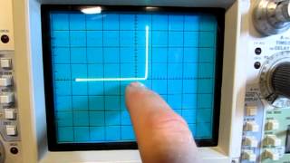
- Component Tester (V-I Curve Tracer) Using The Oscilloscope XY Mode
In this video, I've talked about the XY mode/feature of a Siglent SDS1104X-E oscilloscope and used it in a combination with a Siglent SDG1025 waveform generator to show how you can build an interesting component tester (V-I curve tracer) to test silicone diodes, Zener Diodes, Schottky diodes, LEDs, Resistors, transistors, capacitors .. etc. Also, you can use it to learn about the behavior of the components and semiconductors. You only need to follow a very simple circuit (schematic) and hock the probes to the correct circuit points.
In the video, I have tested these components: 330-ohm resistor, 1N4007 diode, 1N4148 diode, 1N5819 Schottky diode, a white LED and a green LED. the memory depth of the oscilloscope was set on 7M.
========================================
Check other videos: bit.ly/2N9OlPa
========================================
#curve_tracer
#component_tester
#oscilloscope_xy
inspired by:
w2aew
#49: Simple Component Tester using Oscilloscope - Octopus Curve Tracer
URL: • #49: Simple Component ...
w2aew
#197:Simple V-I curve tracer using an oscilloscope and function generator
URL: • #197:Simple V-I curve ... - วิทยาศาสตร์และเทคโนโลยี


Component Tester (V-I Curve Tracer) Using The Oscilloscope XY Mode
A wonderful V-I Curve Tracer example. That is a very nice oscilloscope. 😎 Thank you.
My pleasure!
This is exactly the information I was looking for, thanks so much for making this :)
Glad it was helpful!
That was very nice oscilloscope.
Great video thanks for posting
Bingo
you are my hero
Very claer explanation ❤
Glad it was helpful!
thank you
very nice!
Thank you! Cheers!
good video!
Glad you enjoyed it
Very interesting, thanks you. And... the Y trace that corresponds to the current, what scale is it? (sorry for my bad english)
Yes, Y axis is current (Channel-2). It has been set on 100mV/Div.
@@MyVanitar 100mV=100mA?
@@dapelow No. you forgot about the 10R resistor :-) so it is 10mA. pulsing mode
@@MyVanitar Right, thank you very much
Great video. could you do another one showing the circuit while you're testing it so know where things are placed?
the circuit is pretty simple, if I put the table in the camera focus, the oscilloscope screen would be smaller and harder to watch, so just follow the circuit and don't worry
H Sir, Using the circuit shown in video can i test a 10K ohms resistor? Will i get the expected output. Also the ground of the AFG to be connected to the ground of oscilloscope. To be connected to which ground.
You can test whatever you like, including resistors. all grounds are common. the schematic is clear
Very very useful video. Can I get the Tunnel diode I-V curve by the same way?
Thanks
Thanks, yes it shouldn't be any problem.
thanks alot. it works. test at rigol ms0 5104
Welcome 👍
In the schematics a voltage of 10VPP is applied, now if i do a component test in circuit will this not affect my devices. MY board operates at 5VDC.
in the schematic, I did not show the 10Vpp, it is general. it was my own setup to test a 9V Zener probably. you have to change the input based on your requirement, I should not tell you everything.
When i am doing in circuit measurement and doing resistance measurement i see the waveform for resistor comes like zener diode. Is this due to all component inter connected? If so how to conclude it.
I have no idea. in my case, it shows a line crossing the center, where the slope is the resistance. this circuit is very basic.
Yes, if you're going to test a single component, it needs to be isolated from the circuit. You're likely seeing the other components. The signal going in is AC low voltage, so any transistors, diodes, zeners, or ICs that are connected will change the output. These 'testers' are really for individual components, not really calibrated or suitable for in-circuit testing. If you're testing a rectifier diode, it should look a certain way. A zener has a different look, and a resistor has yet a different look. That's basically what it tells you.
Fantastic. Can I do in normal digital oscilloscopes
if it supports X-Y mode, yes you can
@@MyVanitar please suggest me the oscilloscopes which have. X y
The best bang for buck digital oscilloscope is the one I used in this video. Siglent SDS1104X-E. I have worked with many at this price range and this one is better than all. if you live in the EU, you can purchase it directly from the Siglent German branch.
sir can test resistor & capacitor in-circuit using this method
Yes, of course
I have multiple resistor with one end connected to vcc and other end connected to respective device pins. Basically these resistors are pull up resistors.
90% of the time, when resistors fail, they burn and get black. it means you will notice this from the visual inspection. 70% of the time, electrolytic capacitors show some kind of bulge on their head when they fail, however not all the time. sometimes they get dried out internally. the easiest method is to just take them out and test them. just two pins!
@@MyVanitar In my board i don't see any resistor gone bad (no burn). My board contains lots of components and every time cannot remove each of the resistor and check for it. Instead i wanted to do ICT. How can it be done. In my board i have multiple resistor with one end connected to VCC and other end connected to individual IC pins. How can an ICT be done for this?
@@sanjayparelkar3912 You as a repairman should spot the problem first, not to test all components! There is no tool to test everything fast on the board.
@@MyVanitar sir you are right, but i come across boards where all components looks good from top with no bulg no black out and board is completely dead. So i was think of using ICT methodology.
@@sanjayparelkar5055 You must do reverse engineering and spot the problem. I mean is it from the power supply unit, input/output, ... etc. nobody checks all components. Also if it uses a switching power supply, the main rectifier capacitor might be dried out. as I said bulge is one sign, not always
Sorry, can you tell me the period of the signal? Thanks for share!
have you watched the video completely?
Yes. It works now, but my "short circuit " image is not perfectly straight. I dont know why.
you just need to follow that simple circuit. all grounds are common
@@MyVanitar Thank you 🙏
Can I use 1khz Square wave signal?
I think using the 1KHz signal will put some stress on the waveform generator output, because the load is just a 10 ohm resistor. You can forget about the waveform generator and use a simple step-down 220V-12V or 9V or 6V AC transformer as it delivers a 50Hz sine wave.
@@MyVanitar I built a similar circuit and put it in a project box. It includes a transformer, BNC connectors, mains plug, etc... works the same way. I found your video because I was looking for how to connect it! It's been a few years and I forgot the setting on the oscilloscope (X/Y, etc)... But I used a 120VAC to 6.3VAC transformer, which is safe for just about anything, I believe.
Меандр дает только три точки -U, 0, +U. ничего у вас работать не будет при любой частоте.
Hii
This tester is very simple. You just need to make two-lead sine wave generators. x.y -0-180 degree phase angle inverse sine. Drive with popular ic8038 and even better ad9833 generator .or simple oscillator .transformer or transformerless .opamp. voltage is adjustable from 5v ac to 24v and frequency from 50hz to 1000hz. current should not exceed 1ma to 5mA. it is enough to know the logic of a resistor and a coil.
Yes, I did not claim it's complex. By the way it is quite good in detecting faults in a complex board
@@MyVanitar yes, general explanation. When the block system is put together, it's simple ...everyone can benefit, I don't need to spend a lot of money. . Thanks
Схема неудачная. Для измерений неудобная, так как Канал 1 показывает всегда напряжение на генераторе, а должен показывать кривую напряжения на исследуемой детали.
test it, it works :-)