Measuring a 4-20mA signal without blowing the fuse in your meter

ฝัง
- เผยแพร่เมื่อ 20 ต.ค. 2015
- The first step to measuring a 4-20mA signal without blowing your fuse is understanding how it works.
Items used in the video:
PLC Tools SIM-ALP2 plctools.com/analog-simulator...
Support these videos while you advance your skills courses.twcontrols.com/
A 4 to 20 mA loop will have a output device that produces or regulates a milliamp loop and an input that will read the value. When using a 4-20mA source the positive terminal of the output will go to the positive terminal of the input and the negative terminal of the input will go back to the negative terminal of the analog output.
Examples of outputs could be the position of a valve, a flow meter, temperature, pH, or ORP. Pretty much anything where you need to make a measurement that isn't simply on/off or good/not good. Examples of inputs could be a PLC, display meter, data logger, or a speed control on a drive.
Where a 4-20 mA loop gets tricky is that you can have multiple input devices connected to an output as long as they are all in the loop. So say the input on the right is a PLC and someone wanted a local display. They would cut this wire then connect the plus of the milliamp output to the plus of the local display then connect the minus of the local display to the plus of the next input device.
When troubleshooting a milliamp circuit your first inclination will be to grab your amp meter. It makes sense but this is made to measure big amps, in this ones case, big amps. We need to measure milliamps which is a much smaller meter. If you google “4-20mA meter” then you are going to come up with some expensive solutions such as this Fluke 772. But don't fret. You typical affordable meter such as this one amzn.to/3v4WCaI can measure a 4-20mA signal.
One thing you must pay close attention to when testing a mA signal is down near the terminal post where it says fused. Nearly all volt meters are fused and the post common way to blow a fuse in a volt meter is when checking milliamps.
I've heard of instructors that would give students a lower grade if they blew the fuse in their meters. Students, if this happened to you then sorry about your luck but trust me, you just got a valuable lesson that will help you in the real world. Instructors, if you are doing this will you please stop. If your budget doesn't allow for you have replacement fuses then call us and we will donate some to you.
Now before we can understand how to prevent blowing fuses in our volt meter we need to understand how they get blown. So we take our positive terminal of our volt meter and connect it to the positive terminal of our mA output just like we typically would when checking voltage. Then we take the minus of our voltmeter and connect it to the minus terminal of our volt meter. When reading mA on our voltmeter there is a small fuse in the circuit and for our purposes there is no other resistance in the circuit so we are dealing with a short circuit. So the moment touch these two leads to the circuit we blow the fuse in the meter.
In order to properly test a 4 to 20 mA loop you must be part of the loop. So instead of connecting it across the circuit you must remove one of the wires. It could the positive or the negative wire. Then connect your meter through the loop. Then your meter will only see between 4 and 20 milliamps preventing the fuse from blowing.
Now we are ready to measure our milliamp signal. First we will turn our volt meter to mA, we'll make sure we have the leads in the proper position for measuring a milliamp signal, then we will turn on our SIM-ALP2 which will generate a 4-20 mA signal.
plctools.com/products/plc-too...
We will select a current source and we see that the black post is our common so we will connect it to our multimeters black lead and the red post is our PLC input or in this case the red lead of our meter. - วิทยาศาสตร์และเทคโนโลยี


A great feature is built into many of the Rosemount analog devices. If you open the back and see a test terminal then you can test 4-20 mA without opening the loop. Rosemount build in a zener diode in series in the device, when you usethe test terminal it bridges this 0.7 volt drop diode and you get your 4-20 mA reading. Thank you Tim, and thank you Emerson.
That is a great feature that I didn't know many devices had. I have one from Phoenix Contact sitting on my desk that I'm going to do a video on.
Tim, thank you for the info. I love to learn new things and your video was the best explained by far. Hope you do more.
Thank you Joshua. Will keep making them as long as you keep watching them!
Great videos Tim, thank you for the content you put in TH-cam.
You are welcome Mingo!
Tim.
how do you test if the 4 to 20 mA input on a device is isolated ???
how do you verify if you need a signal isolator ???
Follow-up question: For 99% of platform, the PLC input lead (+) to (-) in DC Voltage should read +/-2v at 24vDC, correct? (Measured + to Ground/PE)?
Hi tim. In order to display 0-10v signal going to plc from a sensor, can i connect this 0-10v signal parallel to a digital panel meter from sensor? Will it affect the signal?
The quick answer is yes. Your analog sensor will have a maximum load it can support but chances are the load of your meter will be minimal.
@Tim Wilborne What would cause an output reading to briefly spike past the desired setting, like up to 20mA and not match the input you have given?
For instance: you are supplying 4 mA initially, you then rotate your knob to 10 mA, and the output jumps from 4 to 20 and then back down to 10?
Can you give a little more detail about the circuit and the devices you are using?
@@TimWilborne Sure, provided from my customer: Controlling electric positioner motor through a Siemens PLC & Wincc station.
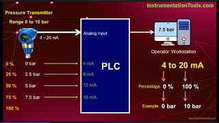
Configured a control on the wincc, from this control we enter the setpoint for controlling the product. This set point is in % [ 0-100 % = 4-20ma] . Now PLC analog output card generates the 4-20 ma input signal for the valve as per the set % value on the wincc control.
The feedback signal [ 4-20 ma] from the valve connected with the PLC analog input module, then it transfers to the Wincc for displaying the actual % of feedback of the valve.
@@MattChance Is the value in WinCC's display showing an overshoot? Is the output in the Siemens controller using a PID?
Tim Wilborne It is showing an overshoot, correct. The setup is: Output from product to Siemens analog output module to Siemens PLC CPU to Wincc. I am not sure if it is using a PID controller. Lets speculate that they are for the moment.
Interestingly, only the output signal spikes, but the product does not react to match the spike, the motor physically moves to its setpoint position as intended.
@@MattChance I've got a great PID series coming out that will explain this but I believe this is a PID controlled output. And in this instance it would not be unusual for a well-tuned PID to go to 100% output yet the physical output work perfectly.
Thank you!
You are welcome. Thanks for watching!
Nice video Thanks
You are welcome
Is there a way of measuring mA without disconnecting wires or using a clamp meter?
Perhaps measuring the voltage across the analog input module and dividing that value by the resistance of the resistor inside the analog module?
Yes, as long as you know the resistor across the terminals then you can do the math and figure it out. It will be in our upcoming analog series.
@Chris Hobbz Hi Chris. I put out a video about that last week. Your method does work as long as the circuit load resistance doesn't change. I've got one coming out in a few weeks on the how load resistance affects this. Let me know what you think of the video below. th-cam.com/video/yv1_BXX4xIo/w-d-xo.html
Hi Tebogo. If you didn't see last weeks video, we went over how a PLC measures a mA signal with a load resistor. As long as you know the load resistance of your analog input, you can do the same thing. Here's the video. th-cam.com/video/yv1_BXX4xIo/w-d-xo.html
Hello I followed the link to the website but I am not seeing the multimeter you show in the video. Can you help me out with that please.
Sorry about that, here is the link to the meter. amzn.to/3v4WCaI
It always bothered me when I bought my meters that it says stuff like 0-600A when really it's 0 or 1-600. Thanks for this vid Tom kind of a simple concept but worth discussing.
Yes, just because it has the range, doesn't mean that it has the resolution to measure down to milliamps. Thanks for watching Jay!
Where is the power source for your diagram ? You are showing an INPUT and an OUTPUT with polarity indications. Having worked as an Industrial electrician,you need a 1- power source, 2-transmitter(current regulator) and 3- sensor. Those three items(four if you count the gauge reading at remote location). Ex: To give a liquid level volume indication of a tank using a mechanical float you need the (sensor)+ the transmitter+ the separate power supply- on older systems. Some newer components may include the PWR supply as an integral part. I appreciate your video on fuse protection, the connection of a meter in SERIES with the above circuit, and NOT parallel is correct. However breaking into a instrumentation circuit can require the circuit to be disabled or can be very tricky unless trained and could trigger alarms and a process shutdown if the affected sensor(s) are safety related," pressure, temperature.etc. " The clamp-on inductive testers eliminate the need to "break" the ckt. which could result in an arc, this is a" No No" in certain facilities where a low flash point vapor may exist. The image resolution in your video is excellent. Quality equipment whatever you used.
It's passive loop (2-wire, loop powered), active loops (4-wire) have external power source...
I blew a $10 fuse in my $30 dollar Klein MM300 thinking that I could test between the + and - terminals on a dustbuster (TM) charger. I can still use the 10 amp side, however I don't know if that would be as accurate when it comes down to Ma or "funny u"f (microfarad). If you're offering free fuses, show me the end of the line! I may have damaged more than just the fuse though, I'm not sure.
My project requires a bit of knowledge that I'm having a tough time finding online. I'm trying to figure out how to use a potentiometer (from a guitar, either 250k or 500k) along with a 23V 400ma DC adapter to drop my current down to ~1ma without affecting the voltage. Tinkering with Ohm's law, it seems nigh impossible without much more than a simple POT. The project is producing colloidal silver with very fine particle size (hence the 1ma along with "high" voltage), think electrolyte solution with anode/cathode. There is a TH-cam video on using a POT and he insists that connected inline ONLY lowers amperage... he does not show a reading for the volts while dialing up/down the POT... I am assuming that the voltage drops substantially. A variable resistor is necessary to keep the 1Ma, since as more silver ions (and colloids) saturate the solution the less resistance the mixture has... thus, increasing Ma over time.
This is the video in case you are interested. Let me know if you believe this would work and have a great Holiday! th-cam.com/video/KgAgsS5h8is/w-d-xo.html
Hola, cuanto es el costo del generador de 4 a 20 miliamper
www.theautomationstore.com/analog-digital-simulator-0-10vdc-and-4-20ma/
Tim what’s the formula on converting 4-20ma signal to hz? Thanks!
Hi Derrick. You can't. They are two different types of measurements. Hz or Hertz is cycles per second and are usually associated with frequency outputs such as encoders. mA is a measurement of amps or current flow. Can you tell me more about what you are trying to do?
Tim Wilborne: trying time figure out on a VFD drive if I send it a 4-20ma signal. If my minimum speed is 15hz so 4ma is 15hz correct? How does it read after that? Like instance if I’m giving it 12ma signal? Thanks!
@@derrickgarcia303 Ah OK I'm following you now Derrick. Typically the drive 4-20mA analog speed range will be 0-60 Hz. The basic equation is Y=mx+B. m= the full range of your Hz divided by the full range of your analog signal. B is an offset if your output signal doesn't start at zero but yours does so let's just concentrate on "m".
The full range of your Hz is easy, 60-0=0. But your 4-20mA signal has what is called a live zero or zero of the scale isn't 0. So 20-4=16. Now take 60/16=3.75Hz per mA.
So if you want 15 Hz, 15Hz/3.75=4. But don't forget about your live zero. So 4 (where your scale starts) + 4 (to get you to 15 Hz) equals 8mA.
Does that make sense?
OMG. You just saved my life. Yes it does. Thank you so much!! Do you have any classes for me to take?
@@derrickgarcia303 Here is a good series on Analog and we have a series on AC Drives coming out soon. www.theautomationstore.com/analog-circuits-training-lessons-on-4-20ma-0-10vdc-and-other-analog-signals/
Milliamp VS Microamp, are they not the same?
Great question Nick! No they are not the same. There are 1000 micro amps in 1 milliamp. 1 milliamp = 0.001 amps. 1 microamp = 0.000001 amps
m = milli = one thousand part, µ = micro = one milion part. More about it can be found here en.wikipedia.org/wiki/Micro-
After resistor 250 ohm, why voltage still 24 v? I mean 24 v to operate transmitter.
As I know, voltage is dropped afer resistor.
See if this one help with what the 250 ohm resistor does th-cam.com/video/yv1_BXX4xIo/w-d-xo.html
If you are looking to drop your voltage, then here is how to do a voltage divider th-cam.com/video/oSh2x-VXFfU/w-d-xo.html
I think one of multimeter fuses blew. I was testing on a couple used 9 volt batteries in series 11 volts. I think I should be picking up some milliamps on your setting 200ma ??I think!!
Hi Kevin, here is how to check it with a second meter th-cam.com/video/S4-HB7knpLE/w-d-xo.html
@@TimWilborne I think I can check with this meter. It has two fuses. I'll check a little later. Thx..
"Voltage across - current through"
It obvious that when measuring the current you have to break the circuit
It may seem obvious since you know, but it is a common mistake.
Yusef Y, if measuring the loop current indirectly, there is no need to break the circuit (loop). Every 4-20mA loop has at least one receiver (called an "input" in this video), and that receiver has a fixed resistance shunt across its input terminals. Use any voltmeter (not to be confused with a milliammeter, which the presenter in this video mistakenly calls a "voltmeter") to measure the voltage drop across that shunt resistance, which means measuring the voltage across the terminals of that receiver/input. The voltage will be precisely proportional to the loop current. This is the way the professionals in industry test their 4-20mA current loops without breaking the loop/circuit. It gives a result at least as accurate as what can be measured by inserting a milliammeter into the loop, and you won't be risking blowing any fuses, and you won't be disturbing the process control by breaking the loop.
Already blew the fuse
Welcome to the club, I have blown plenty of them 😂