This is the top ten basic circuits, from them we can understand how op amps work to set out to build hundreds of final project circuits. the circuits are: 1- 2:17 Buffer 2- 3:56 Inverting Amp 3- 5:54 Non Inverting Amp 4- 7:29 Inverting Summing Amp 5- 9:25 Differential Amp 6- 10:50 Op Amp as Integrator 7- 12:36 Op Amp as Differentiator 8- 14:51 Op Amp as IV (Current to Voltage Converter) 9- 15:58 Op Amp as Peak Detector
loving all your videos!!! And learning soo much! You sir are an EXCELLENT teacher of a very to say the very least challenging skillset. On my way to tackling some synth circuits. Big cheers to you!
Thank you so much Paul. This video is like a part of an essential encyclopedia. (Wanted to add that it was funny to see a bottle of Gatorade appearing at 10:50 with the *InteGATOR* example)
Thanks, Paul. This gives me some insight into what I may have done wrong with a circuit that I was trying. I will give it another look but probably keep the alternative that I came up with using a pair of transistors instead as it give me more control of the overall sensitivity of the circuit.
While I enjoyed your video, I have to point out that the first circuit you present, the buffer, is completely wrong. In this type of circuit, the inverting input is tied only to the output, and the voltage to be buffered is connected to the non-inverting input. The circuit you drew would not work at all.
@@NelsonLukwago-hr4vw The Op-Amp will work to keep the difference between the inputs to zero. Since the + input is tied to ground, the Op-Amp will supply current to the negative input to counteract any signal you put in there (up to the current capability of the Op-Amp). So, essentially you are creating and active short circuit to ground.
Ha! Brings back memories of my Senior Mechanical Engineering project in college in 1975. I put together a system to draw a three dimensional isometric projection of moving air in a duct. I had to cobble together two computers - one digital and one analog (with a huge number of patch wires). The system worked the first time I fired it up. I was more surprised than my professor :-)
Atta-boy, Paul! Good stuff. The one additional thing I was wanting was an example of where each design is employed. Why, because I don't know. lol. An example might be that a buffer amplifier is commonly used in audio amplifiers to drop the output impedance to match it to the low impedance that speakers commonly used. I must admit that I don't even know if that is exactly correct, but it serves as an example, I guess. Blessings.
YOU MISSED THE COMPARATOR CIRCUIT! ITS ONE OF THE MOST USEFUL ONES THERE IS WITH AN "OP-AMP.!! PLEASE PAUL, DO A VIDEO ON THE OP-AMP COMPARATOR. IT COULD FILL A VIDEO JUST BY ITS SELF..
@@adailyllama4786The correct way is input (high impedance) should be connected to the non-inverting terminal of opamp and the inverting terminal should be connected to the negative feedback from the output (low impedance).
Class D amps use a triangle wave vs the music or sine wave. The output is a sq wave with varying duty cycle that re-creates the sine wave. I find that amazing.
Thanks alot Sir. It was sweet and simple 👌🏼 I'm trying to build some practical circuits and most of the time I mess up with powering the circuit . So if you could then please make a video on it.
so your buffer example uses the non inverting at ground and the inverting is the feedback plus the input for the voltage but all other examples I've seen have the non inverting for the input and the inverting is the feedback what is the difference as i breadboarded both and they both work just as expected
it seems to work, because it's literally just a short circuit. this guy appears to have drawn the entire circuit wrong. you connect the non-inverting input to your desired input, and the inverting input to the output. this creates an amplifier with a gain of 1 and therefore mimicks the input almost exactly. your circuit seems to work, because you've probably just shorted the input to the output like on the video. this has no effect for separating the signal.
What would really help is WHY???? they are used in each case. For example - why and where is an inverting amp used??? Give several examples for each please.
Thanks . Please tell more about op amp . Particulary what happens in internal circuit of op amp and the circuits connected to it that are including resistors and capacitor as you mentioned !
You may want to watch Dave Jones' (EEV-blog) and Bob duHamel's (RSD academy) video's on opamps for the really deep dive. However, I would so very much love to see a third more basic and directly comprehensible angle on this from our favorite uncle here, in that special perfect direct way that only he can!
Oh man! I have been looking for ages for an op amp circuit, and I thought it would be among yours - but it wasn't, so I'm still looking. What I want is a circuit that will give an output between two voltage levels. For example ... Input output < 2.4V State A (eg. High) 2.4V ... 2.6V State B (eg Low) > 2.6V State A What I want eventually is an LM324 circuit that will light R, G or B for 3 distinct input voltage ranges. There are lots of circuits for VU meters, and it's easy to light R and G and B, but I want to light R or G or B. This is a teaching project for my grandson (to be kept under wraps until I have taught myself!) Damn analogics! It would be so easy in a uProcessor with if...then statements!
@@learnelectronics Ideally, yes - but an op amp makes a good enough comparator as long as speed is no concern. Anyway, I've found what I was looking for. If I ever knew the term, I had forgotten it, but the type of comparator I wanted is called a Window comparator - and once I had found that, I was able to do a web search, and found lots of info. My grandson (7) took an LM324 off a discarded board (unsoldered it!), and he has some RGB LEDs, and wants to do something with them, so I was casting about for an application for him. Of course, there are lots of things to do with a 324, and I have other ideas too, but they require higher speed, so a 339 would do better. Thanks for chipping in.
True, for the buffer circuit, the output has to get routed back to the inverting input and the non inverting input has to be connected to the voltage source. With the circuit shown in the video, a virtual ground is being created at the inverting input, which means that the output and input both are getting pulled to ground level. So its basically just a short circuit.
Very informative as usual:) I'm trying to figure out the voltage swing on specification on op amps. Would it be the same thing or similar to a beta specification on transistors?
You’re looking for the gain. The formulas Paul gave for each circuit are used to calculate the gain which is determined by the values of the components used in the circuit.
You missed out the Comparator. Basically, the output goes high when the non-inverting input is higher than the inverting input and vice-versa. One major use it to feed a triangle wave into one input, and a variable voltage into the other, and you'll get a PWM (pulse width modulation) signal out where the duty cycle is dependent on the voltage in.
A sine wave will work but the output won't be linear to the input. You'll get very little change in output for the first and last 25% of the input range. That's not necessarily a bad thing though, especially in some servo applications where you might want a little more finesse towards the extreme ends of travel...
since first viewing modular synth circuits a quarter century ago, i decided they were unfeasible because op amps require fiddly negative power and are relatively expensive components. (i went into audio dsp, which i have been able to more easily afford since :) - NOW i find out you can use them without negative power???!?!?!?!?!??!! is there an overview??! i love simple things.. bridged T circuit for percussion sounds :)
your buffer looks really off. it seems like that's a short circuit from the inverting input to the output. i've always seen them drawn as, noninv - input, inverting is connected to output. your just seems wrong. please enlighten me
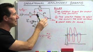
4:35 "and.. the PHASE has become inverted" Don't you mean the POLARITY has become inverted ? the Phase is neither inverted , Nor offset by 180 deg. the POLARITY has been inverted, hence INVERTING amplifier


Such videos are gem of Internet. I finished my college 15 years back and these refreshers really bring back some good memories : ).
This is the top ten basic circuits, from them we can understand how op amps work to set out to build hundreds of final project circuits.
the circuits are:
1- 2:17 Buffer
2- 3:56 Inverting Amp
3- 5:54 Non Inverting Amp
4- 7:29 Inverting Summing Amp
5- 9:25 Differential Amp
6- 10:50 Op Amp as Integrator
7- 12:36 Op Amp as Differentiator
8- 14:51 Op Amp as IV (Current to Voltage Converter)
9- 15:58 Op Amp as Peak Detector
Great list! Please go back through the list and give us an example of where each circuit might be used. Thank you.
I guess I might have F in arithmetic but I see only 9
loving all your videos!!! And learning soo much! You sir are an EXCELLENT teacher of a very to say the very least challenging skillset. On my way to tackling some synth circuits. Big cheers to you!
Thank you so much Paul. This video is like a part of an essential encyclopedia.
(Wanted to add that it was funny to see a bottle of Gatorade appearing at 10:50 with the *InteGATOR* example)
I can use this video to show others that when you have great knowledge you explain it like a butter to others.
Thanks, Paul. This gives me some insight into what I may have done wrong with a circuit that I was trying. I will give it another look but probably keep the alternative that I came up with using a pair of transistors instead as it give me more control of the overall sensitivity of the circuit.
While I enjoyed your video, I have to point out that the first circuit you present, the buffer, is completely wrong. In this type of circuit, the inverting input is tied only to the output, and the voltage to be buffered is connected to the non-inverting input. The circuit you drew would not work at all.
Thanks for pointing that out, I just went crazy, I thought I learned it wrong. I would work, but the output would sink current, not source it.
Why
@@NelsonLukwago-hr4vwhe just explained it in the comment 😭
Yeah, I was going to mention that.
@@NelsonLukwago-hr4vw The Op-Amp will work to keep the difference between the inputs to zero. Since the + input is tied to ground, the Op-Amp will supply current to the negative input to counteract any signal you put in there (up to the current capability of the Op-Amp). So, essentially you are creating and active short circuit to ground.
I think you made a mistake on the buffer circuit- shouldn’t Ve go to non-inverting input, with no connection to ground on either side?
Great video been watching a lot of your stuff recently leaning the 555 timer ic and the buffer looks interesting for my scope output x
Ha! Brings back memories of my Senior Mechanical Engineering project in college in 1975. I put together a system to draw a three dimensional isometric projection of moving air in a duct. I had to cobble together two computers - one digital and one analog (with a huge number of patch wires). The system worked the first time I fired it up. I was more surprised than my professor :-)
Atta-boy, Paul! Good stuff. The one additional thing I was wanting was an example of where each design is employed. Why, because I don't know. lol. An example might be that a buffer amplifier is commonly used in audio amplifiers to drop the output impedance to match it to the low impedance that speakers commonly used. I must admit that I don't even know if that is exactly correct, but it serves as an example, I guess. Blessings.
Nice video! I'm trying to see more practical and not so academic videos, so this was good
That was a great video Paul! Perfect overview of what people can do with OpAmps
This is a great reference video for an important topic and component
YOU MISSED THE COMPARATOR CIRCUIT! ITS ONE OF THE MOST USEFUL ONES THERE IS WITH AN "OP-AMP.!!
PLEASE PAUL, DO A VIDEO ON THE OP-AMP COMPARATOR. IT COULD FILL A VIDEO JUST BY ITS SELF..
That voltage follower schematic is wrong.
OK then, tell us the correct way.
Please explain?
@@adailyllama4786The correct way is input (high impedance) should be connected to the non-inverting terminal of opamp and the inverting terminal should be connected to the negative feedback from the output (low impedance).
Yep, voltage follower should be shown like this: www.allaboutcircuits.com/uploads/thumbnails/Voltage_follower.jpg
He likes being a comedian. He does this once in a while :)
Class D amps use a triangle wave vs the music or sine wave. The output is a sq wave with varying duty cycle that re-creates the sine wave. I find that amazing.
3:05 i think your feedback is wrong, it creates a short from input to output.
Thanks alot Sir.
It was sweet and simple 👌🏼
I'm trying to build some practical circuits and most of the time I mess up with powering the circuit . So if you could then please make a video on it.
Wow! Thanks. Just got my first batch of LM328's looks like it's breadboard time.
i had no luck with an active integrator last time i tried. But a passive on the end of a 555 timer output for my class D amp worked perfect
Very interesting and informative video. Thank you Paul.
Your an excellent simple to follow teacher. Thanks for sharing :-)
so your buffer example uses the non inverting at ground and the inverting is the feedback plus the input for the voltage but all other examples I've seen have the non inverting for the input and the inverting is the feedback what is the difference as i breadboarded both and they both work just as expected
it seems to work, because it's literally just a short circuit. this guy appears to have drawn the entire circuit wrong. you connect the non-inverting input to your desired input, and the inverting input to the output. this creates an amplifier with a gain of 1 and therefore mimicks the input almost exactly. your circuit seems to work, because you've probably just shorted the input to the output like on the video. this has no effect for separating the signal.
What would really help is WHY???? they are used in each case. For example - why and where is an inverting amp used??? Give several examples for each please.
Thanks Paul, very nice. So what do you get with a capacitor on the input and feedback too ?
Cool. Very thorough.
Thanks Paul ☮️
Thanks . Please tell more about op amp . Particulary what happens in internal circuit of op amp and the circuits connected to it that are including resistors and capacitor as you mentioned !
You may want to watch Dave Jones' (EEV-blog) and Bob duHamel's (RSD academy) video's on opamps for the really deep dive. However, I would so very much love to see a third more basic and directly comprehensible angle on this from our favorite uncle here, in that special perfect direct way that only he can!
Oh man! I have been looking for ages for an op amp circuit, and I thought it would be among yours - but it wasn't, so I'm still looking. What I want is a circuit that will give an output between two voltage levels. For example ...
Input output
< 2.4V State A (eg. High)
2.4V ... 2.6V State B (eg Low)
> 2.6V State A
What I want eventually is an LM324 circuit that will light R, G or B for 3 distinct input voltage ranges.
There are lots of circuits for VU meters, and it's easy to light R and G and B, but I want to light R or G or B.
This is a teaching project for my grandson (to be kept under wraps until I have taught myself!)
Damn analogics! It would be so easy in a uProcessor with if...then statements!
You want a comparator not an opamp
@@learnelectronics Ideally, yes - but an op amp makes a good enough comparator as long as speed is no concern. Anyway, I've found what I was looking for. If I ever knew the term, I had forgotten it, but the type of comparator I wanted is called a Window comparator - and once I had found that, I was able to do a web search, and found lots of info.
My grandson (7) took an LM324 off a discarded board (unsoldered it!), and he has some RGB LEDs, and wants to do something with them, so I was casting about for an application for him. Of course, there are lots of things to do with a 324, and I have other ideas too, but they require higher speed, so a 339 would do better. Thanks for chipping in.
I think input signal should go to non-inverting input in buffer circuit.
True, for the buffer circuit, the output has to get routed back to the inverting input and the non inverting input has to be connected to the voltage source. With the circuit shown in the video, a virtual ground is being created at the inverting input, which means that the output and input both are getting pulled to ground level. So its basically just a short circuit.
Thank you for the great video.
Great review. Enjoyed. Thanks,Paul.
Very informative. Thank you for making it.
Very informative as usual:) I'm trying to figure out the voltage swing on specification on op amps. Would it be the same thing or similar to a beta specification on transistors?
You’re looking for the gain. The formulas Paul gave for each circuit are used to calculate the gain which is determined by the values of the components used in the circuit.
Question Paul have you heard of or ever used any kits from Mitch Electronics? They are based in the United Kingdom?
No I haven't
Very cool Paul, thanks.
Great job, very useful
This Is All Very Handy In Circuitry, I Consider My Knees To Ground While Praying An Op-Amp Of Sorts.
You missed out the Comparator.
Basically, the output goes high when the non-inverting input is higher than the inverting input and vice-versa.
One major use it to feed a triangle wave into one input, and a variable voltage into the other, and you'll get a PWM (pulse width modulation) signal out where the duty cycle is dependent on the voltage in.
Yep
I think sine wave can also be used similiarly for PWM
A sine wave will work but the output won't be linear to the input. You'll get very little change in output for the first and last 25% of the input range. That's not necessarily a bad thing though, especially in some servo applications where you might want a little more finesse towards the extreme ends of travel...
Interesting and useful.
After the buffer schematic I decided it might be best to abandon watching this video.
Yeah he got the totally buffer wrong
Should have given input at + and connected - to output
But most of his videos are usually awesome
Yep, I was shaking my head, the circuit he drew would totally not work. Not a good start.
Nice video! Keep up
since first viewing modular synth circuits a quarter century ago, i decided they were unfeasible because op amps require fiddly negative power and are relatively expensive components. (i went into audio dsp, which i have been able to more easily afford since :) - NOW i find out you can use them without negative power???!?!?!?!?!??!! is there an overview??!
i love simple things.. bridged T circuit for percussion sounds :)
Thanks 👍
This Voltage Follower is wrong!! You put the FB to the inverting input, but the signal to the non-inverting input, which you grounded.
My boss agrees
16:27 - I believe you meant to say "there IS a connection here".
No there is no connection there
The diode is connected to ground via a Capacitor , the input Vs has no role there
Awesome bud bud
your buffer looks really off. it seems like that's a short circuit from the inverting input to the output. i've always seen them drawn as, noninv - input, inverting is connected to output. your just seems wrong. please enlighten me
4:35 "and.. the PHASE has become inverted"
Don't you mean the POLARITY has become inverted ?
the Phase is neither inverted , Nor offset by 180 deg.
the POLARITY has been inverted, hence INVERTING amplifier
11:00 Integrator has an R. Integator is - an alligator that fits between things? 😂
Add ideal diode, and you got it.
2:20 lol I thought you said Butt Fur 😂
Comparator? :|