Great video but there is a math error. You said I_s = 342mA but, (10-6.8)= 3.2 and 3.2/10 = 320mA not 342mA, Therefore your resistor value would be < ~39.31ohms. SO for the other R value would have to be 21.32 ohms 21.31 < R < 39.31
This is the first time I've heard any talk of a minimum CURRENT to turn on the Zener diode. All the videos I've seen just speak of the Zener VOLTAGE necessary to turn it on, in the reverse bias mode. Could you possibly explain this concept of minimum current eg. is this a minimum current for the diode to function AFTER the Zener voltage is achieved?
Thank you for all of the valuable information on zeners...I have a question to which I can't find the answer: I am using a 600v zener regulator (three 200v zeners in series with an 800v DC input) which works great, HOWEVER, I now need to input 800v --AC-- into the standard zener circuit at a few kHz. So... Can an 800v --AC-- signal be used as the zener input through the input resistor??? I need a negative dip in order to turn off the circuit with an SCR. MUCH THANKS!
Zener diodes can be forward biased and in theory would act like a regular diode. You would want to check the forward current capabilities though since you'd likely have more current through the diode when forward biased.
Just so you know how good you are at teaching, I'm a french speaker, and i totally understood how to do my homeworks after watching you video. Thank you Could you just explain how you knew what Rs you had to use ? You have chosen 10ohm for the safety resistance but if i take a power supply of 24volt, is 10ohm still enough to protect the zener ?
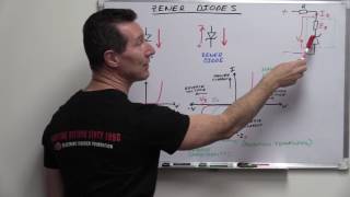
Rs controls how much current goes to the parallel combination of your zener diode and load. Is (source current) = (Vsource - Vzener)/Rs will give you that current. If you know what your load current is and you know what the maximum current the zener diode can handle is, then you can figure out what Is will be and from that you can calculate the required Rs. regards to Cersei
i am making a 5v usb charger maximum 5A from a LM1084IT ADJ. ... i want to protect the output to know more than 5.6v to obviously protect the phone thats being charged incase something goes wrong with the regulator..can i use a BZX84-C5V6 SMD 5.6V 250mW and would i need a resistor in series with the diode ? hope you can help
If I have a piezo element and an input pin (for instance a digital input pin of an arduino), could I use the protection at around 4:00 to protect this pin with a zener diode rated at 5 volts? Or does the pin need more protection since a piezo element is able to create big voltage spikes.
Since the zener doesn't conduct until the input gets to 5V, all of the current will go through the resistor; it will be as if the Zener diode wasn't even there.
@@ElectronXLab Thanks. Haha I actually figured it out after I posted this. But I really appreciate your effort in educating people... Hope u don't mind but...what happens when the supply is just equal to the zener voltage @6:35? Would the current just flow to the 500 ohm resistor(and not through the zener diode branch)?
is the zener diode essentially a short circuit when current is flowing through it? If so, why how does current flow through the load resistor when the zener diode is active for the last example?
It's kind of a short circuit, but one with a voltage across it. Think of it more like a voltage source that sinks current (i.e., allows current to flow through it).


![[LIVE] : ONE ลุมพินี 83 วันนี้!! คู่เอก "พันฤทธิ์ vs ซุปเปอร์บอล วันของโอม MBK"](http://i.ytimg.com/vi/1b4pkKHa_Fk/mqdefault.jpg)


About time we get some decent circuit analysis explanations without a thick Indian accent that is impossible to understand
Thank you very much for this explanation, the comparison with the rectifier diode side by side sold it to me. Thanks.
You saved my life. Who else having exam tomorrow?
Pravin Ron me)))
me hhh :p
Great video but there is a math error. You said I_s = 342mA but, (10-6.8)= 3.2 and 3.2/10 = 320mA not 342mA, Therefore your resistor value would be < ~39.31ohms. SO for the other R value would have to be 21.32 ohms
21.31 < R < 39.31
+The Ranger Talk correct
that's embarrassing
This is the first time I've heard any talk of a minimum CURRENT to turn on the Zener diode. All the videos I've seen just speak of the Zener VOLTAGE necessary to turn it on, in the reverse bias mode. Could you possibly explain this concept of minimum current eg. is this a minimum current for the diode to function AFTER the Zener voltage is achieved?
Thank you for all of the valuable information on zeners...I have a question to which I can't find the answer:
I am using a 600v zener regulator (three 200v zeners in series with an 800v DC input) which works great, HOWEVER, I now need to input 800v --AC-- into the standard zener circuit at a few kHz. So...
Can an 800v --AC-- signal be used as the zener input through the input resistor??? I need a negative dip in order to turn off the circuit with an SCR.
MUCH THANKS!
Zener diodes can be forward biased and in theory would act like a regular diode. You would want to check the forward current capabilities though since you'd likely have more current through the diode when forward biased.
Thanks very much,
Would the output voltage drop still be about 0.7v? or would it be -high?
very good explaination..thanks bro.
Just so you know how good you are at teaching, I'm a french speaker, and i totally understood how to do my homeworks after watching you video.
Thank you
Could you just explain how you knew what Rs you had to use ?
You have chosen 10ohm for the safety resistance but if i take a power supply of 24volt, is 10ohm still enough to protect the zener ?
Rs controls how much current goes to the parallel combination of your zener diode and load. Is (source current) = (Vsource - Vzener)/Rs will give you that current. If you know what your load current is and you know what the maximum current the zener diode can handle is, then you can figure out what Is will be and from that you can calculate the required Rs.
regards to Cersei
David Williams thanks for your answer :)
and thanks from cersei too :D
i am making a 5v usb charger maximum 5A from a LM1084IT ADJ. ... i want to protect the output to know more than 5.6v to obviously protect the phone thats being charged incase something goes wrong with the regulator..can i use a BZX84-C5V6 SMD 5.6V 250mW and would i need a resistor in series with the diode ? hope you can help
nice usefull video.
which software you used to make this tutorial?
If I have a piezo element and an input pin (for instance a digital input pin of an arduino), could I use the protection at around 4:00 to protect this pin with a zener diode rated at 5 volts? Or does the pin need more protection since a piezo element is able to create big voltage spikes.
Hi, may i know how can i calculate Iz and IL with zener impedence and knee/test currents?
Really need it for a test, thanks!
What program are you using to draw all this digitally
on the graph of @4:42....wouldn't the positive have be like a square wave since the zener only conducts at 5v?
Since the zener doesn't conduct until the input gets to 5V, all of the current will go through the resistor; it will be as if the Zener diode wasn't even there.
@@ElectronXLab Thanks. Haha I actually figured it out after I posted this. But I really appreciate your effort in educating people...
Hope u don't mind but...what happens when the supply is just equal to the zener voltage @6:35?
Would the current just flow to the 500 ohm resistor(and not through the zener diode branch)?
Using I and V on the axis seems rather inconsistent. Still a good explanation.
Thank you, I will take it from here.
The efficiency goes up the closer the source voltage is to the desired load or Zener voltage.
is the zener diode essentially a short circuit when current is flowing through it? If so, why how does current flow through the load resistor when the zener diode is active for the last example?
It's kind of a short circuit, but one with a voltage across it. Think of it more like a voltage source that sinks current (i.e., allows current to flow through it).
thank you!
thank you ^-^
thank you man
at 11:47 where is this "load resistor" that you spoke of, it is not labeled on the diagram.
The resistor at the far right is the load resistor.
thank you
ptc resistor is called
thermistor
varistor?
zener diode connection in a ckt always
series
forward
parllel
reverse
dont know ...tell me.
555