God I'm glad there're people like you out there giving us school drop-outs a free education. I loved all this (and science in general) at school but I had far more pressing matters to consider back then. Cheers man.
Thanks to Clive for the led info. I am a retired electrician and have s huge interest in these. I retired just before the industry changed. Now I am also a radio ham and the floods I bought on eBay wiped out the HF band's. No suppression of harmonic squarewaves at all from the driver. Due to your video of driverless LEDs which I knew nothing about I have now bought some to test and will swap over if ok. Glad to say totally quiet. The two 20 watt ones check out as 20 watts on my power meter but the two 50w chips way below ,one at 17 w the other 25 watts. They are perfectly useable still as after 30m still running ok with no signs of any problems. I mounted thst one on a heat sink for a lengthy test. Thanks again Clive for your wonderful information videos. I will never buy these floods again . They came from a UK based company hoping they are legit, but No.
Clive, might i suggest, that rather than attempting to solder onto those pads with a soldering iron, you instead use a hot-air wand and solder paste. It works much better, and faster, just be sure to place an angled aluminum piece to act as a shield to prevent the hot air from damaging the LEDs. Oh, and you need a much larger calculator, my nan couldn't read that from her house a few miles away :D
Hi Clive, I'd just like to tell you how interesting and informative I find your videos. Although I've had some peripheral involvement with electronics in my life it's only now that I'm in my dotage I've started studying it more closely. After watching your dissection of various things I'm starting to understand the circuitry of the objects more and more. Thank you so much, keep up the good work. Best regards!
Dear Mr. Big Clive, I am a recent subscriber to your channel and have been enjoying your videos immensely, in spite of the fact that I am a lowly software engineer and have a paucity of erudition and experience when it comes to matters electronic. I find your attention to detail, combined with your casual in-passing remarks on the deliterious affect of mains voltage on the kind of day one could end up having, to be educational, informative and entertaining. I particularly enjoyed the Fishocutor video. Last week when checking the Sunday roast to see if the juices ran clear I noticed they hadn't, I said, in accent that approximated yours, "That's not good." and promptly returned the beastie to the oven.
I just ordered a driverless cob from a Chinese company . My brother told me he saw a u tube video where a guy bought a cob and glued it to a heat sink and got he wrong glue by mistake causing the thing to melt thru the granite table top and into the floor due to a over heat. I know you would know if this was possible or not? I have learned allot from watching you videos. I have been taking thing apart since the age of 4 .I have always marveled at how electronics are put together.I wanted to become a electric engineer but lost interest when I got older but still love to take things apart . Thanks for making these videos the way you do they are very illuminating .
Too bad there are no solder pads for connecting an external smoothing capacitor. Those things are so cheap that they would make very nice lights if the flickering problem could be solved. Of course a bit of scraping and tagging leads directly to the output of the rectifier might be possible, but not very easy.
Hm, maybe even add an external bridge rectifier and a smoothing capacitor on the input side and just let the current flow through one half of the rectifier on the board... Maybe I should get a few of these and experiment a little.
Eden's Aquaponics i was thinking the same thing. But if you only have a single phase, is it possible to make circuit that can make a delay in phase so second unit will be on, while the original is off? That way, with two units, you could have simple smoothening effect... of course, leds must be close to each other.
Clive, thanks for this video which is still relevant. Just acquired 6 of these for growlights. It occurred to me that connecting the mains to a bridge rectifier and say a 50uF electro capacitor and feeding the smoothed DC to each of the chips in parallel would avoid having to add a capacitor to each chip.
That would work, but keep in mind that the voltage will rise to the peak mains voltage, so the regulator chips will run a lot hotter. I'd also recommend adding a couple of 330K resistors in series across the capacitor to slowly discharge it when unplugged and help reduce the risk of a shock from the charged capacitor when working on your lights.
BigClive, I have a way of getting silicon off if you don't have silicon solvents or other stuff, a soft wire brush will remove the silicon and leave the components virtually undamaged, Just a tip. Many thanks and great work.
Better than a CFL, but grow lights have a spectrum tuned for growth. Purpley, no green in it (reflected by leaves). But you can't beat the price of these white ones.
I've a couple of these warm whites, cooled with cheap CPU coolers, growing some "flowers". The plants love them, they don't care about the flicker. They last long with minimal heat when running with active cooling. Heat them first on a clothes iron to assist with soldering.
You should definitely get some proper tools to measure light emission, because your reviews are very interesting and getting the lm/W value would be the cherry on top.
I installed 5 of these in my shop today after seeing this video a couple of weeks ago. 120v in USA. Have no flicker at all. Will be installing a lot more. I like the 180 degree angle. Thanks for the video.
Mounted them on some 8" aluminum channel for now. Waiting to see how they last then I'll machine some fixtures for them. (2) 50w on 8" x 3" x 1 1/2" channel works good. Each 50w is mounted about 1 foot from the end. Have some 30w coming.
With the flicker and using for street lights, if you put each light on a separate phase of the the 3, would they flicker in sequence, as the sine wave is offset from each other?
I think I noticed a slight 3 phase 'chaser' effect in the stadium lights at the london olympics in the ultra slo mo playbacks. don't know what was actually in those fixtures, would guess that it wasn't LEDs though. afaik 100Hz strobing isn't usually much of a problem unless you're operating rotating machinery when it can make things that are spinning look like they're stationary.
Thanks for these videos. You got me hooked on COB LEDs now. I bought a few of these 50 watt units myself, but wanted to improve efficiency while reducing heat. I was thinking of disabling one of the 5 driver chips to knock power down by 20%.
I'm a bit suspicious those chips are the same as in 5mm LEDs. I also have a couple of those LEDs and the chips are sooooo tiny! The 20W, 30W and 50W versions all seem to have the same chips (and the same number of them), this is weird.
seems a weird way to accomplish the end goal.. but that must mean they are just driving the chips must harder in the higher rated LEDs? probably not great for reliability or longevity in the higher rated units. Interesting tho.
The flickering he is talking about is at 100Hz, its not a big problem on the human eye otherwise nobody would go to movies where the flickering is at 48 Hz, but its a its a major problem for tv camera. If you have put a few hundred nF cap on your circuit it does'nt made much of a difference but if you have a few 10's micro F its certainly flicker free and a lot brighter but not for long.
I'm using mine to shoot 1000+fps so the flicker was quite evident on camera. I threw a 220uf in because it was what I had on hand but I don't see how it would cause the lights to fail early. It still draws the same average current as before and dissipates the same power unless the 80% duty cycle was used a "cool down" time.
A 220uF 400V is huge If you put it behind a rectifier it will keep the DC voltage at AC peak about 330V in this case supplying 4.5V to each LED well above its operating limits. What are the physical dimensions and the rated voltage of your cap?
I don't have a fraction of the electronics knowledge you have, but I have been experimenting with both the DCV LEDs, and the integrated power supply LEDs for use as shop lighting in my fab shop. I have had NO problem whatsoever with flicker. I've tested everything from 20W to 150W integrated, (at 120vAC), and have been operating individual lighting implementations around the house, and in the shop, as trials. The only problem I have had is with early failure in some 'full spectrum' integrated LEDs I built for my wife's plants. I enclosed full spectrum because the LEDs were actually so damn red, they made the entire house glow red during the day! So much for full spectrum. I ended up mixing them with equal wattage cold whites at a ratio of 6 red to 4 cold whites to get a decent color that wouldn't make the plants continually what to flower. The problem I've had is the lights are failing at about a 25-30% rate after two months of daily use. Have you tested any of the integrated/driverless LEDs at 120vAC to see if the flicker still exists? Some of the eBay chips I've looked at have 110-250vAC, and some have either 120vAC or 240vAC inputs. I've tried some of each, at different wattages. Something I was told, and verified, was some brands, and sellers on eBay sell a better quality LED; gold vs copper conductors, and copper vs aluminum bases. They are not more expensive, which is confusing. The early failure 'full spectrums' were not the gold/copper type. I've had no failures in the gold/copper LEDs. Any thoughts on this? Thanks for your vids...
It tells you how much voltage and current are in sync. A pure resistive load always has 100% power factor (when the voltage is highest, the current is as well; when you are at half the max voltage you're also at half the max current aso. ; that's just Ohm's law). The more the shapes of the voltage curve and current curve differ (phase shift or general shape), the lower the power factor.
In a capacitive circuit you have a big inrush current as it's resistance at the start of the cycle approximates zero. As the voltage on the plates builds up the effective instantaneous resistance increases. IE the current leads the voltage. With an inductor because of magnetic field effects inducing back EMF (a reverse voltage) when the current is changing, then the current at the application of the voltage is at it's lowest and keeps rising until parasitic resistance limits current. IE Current lags behind voltage. In an AC circuit the lag and lead can be expressed as an angle and I think it is the sine of the angle that gives you the power factor number, as it is directly proportional to the ratio of real and apparent power. That said it's a long time since I studied this and most of what I work with is sub 1mW, and working in the frequency domain not time domain for analysis.
For regular folks, the power factor is essentially irrelevant, as the power company doesn't track that kind of stuff on your residential electricity bill, nor have a way to measure it with your regular residential meter. Industrial customers, with large banks of motors(inductors) like some sort of factory, probably do get that monitored and often put in capacitive banks to fix their power factors or get charged for the power company to do it. It is kind of an academic and engineering nerdy thing to worry about for most.
True in 90% for domestic users. However in some areas of Australia the domestic meters for people with large power banks and solar roofs do track power factor (partly to check that your system is putting power into the grid correctly). Also here in the UK all industrial units supplied with three phase have power factor tracking meters and you get fined if it is outside a set range.
The reason the knife moves in such a way because when cutting plasterboard (Drywall) the blade gets covered in gypsum dust, which clogs the mechanism of a standard retractable knife. I use a folding lock knife.
Makes you wonder whether the next generation of these devices will include some form of on-board smoothing? As you note, electrolytics do have their own lifespan problems, but having an easy-to-change "Capacitor module" might be attractive to Municipal users? Alternatively the chips might be used to drive a thin phosphor layer with a modest decay profile, so eliminating a lot of the flicker? If there is the will to use these VERY simple devices, a way WILL be found to cost-effectively overcome their limitations.
I agree with the other suggestions: the cheap Chinese hot air gun and some eBay special solder paste is the way to go. Or just the hot air gun to pre-heat the board before regular soldering, but I do love me some solder paste :D
Wouldn't it be possible to put an own rectifier and capacitor before the the L and N plates and just feed it an already pre-rectified and stable DC signal? I mean, there would be some more energy lost but I think that it should make the flickering stop. Or am I missing something here? EDIT, In case someone reads this: Just after this video finished I saw there is a follow up video for this, where this exact option was talked about it turns out, that it is possible.
Well, i think of a driver as something standalone that alters incoming voltage to feed the need of an led. If the diodes themselves run on mains, then i suppose no, there are only safety measures like regulators and resistors from what I saw. Might be totally wrong, thats just how i understood things.
Clive, have you tried shimming the gap between the heating element and tip? My chinese hakko ripoff can solder to these things with no troubles at all, and thats while they're stuck down to a heatsink. Also curious, what happens to both power draw as well as thermals if you bridge an electrolytic across the bridge rectifier?
+Luke Den Hartog I've not tried shimming the iron yet. I considered the electrolytic. It would increase the voltage across the current limiting chips and probably cause then too go into thermal limiting mode.
Perhaps two smoothed chips wired in serial? The voltage boost from the smoothing capacitor would be mitigated by splitting the AC voltage between two of these LED chips.
I've found that my Chinese "Weller" copy instant-heat iron works just fine on these boards. Seems to deliver the heat nice and quickly, with minimal heating of adjacent components.
Try putting a cap at the output of the chip, as regulator chip datasheet recommended. Might able lower the flicker but brightness will go low/high and add will add extra load to the chips. worth the try
Clive, use a small wire brush on the silicone, smd parts usually handle it fine. I want to say soaking it in warm lacquer thinner (toluene) to make the silicone softer and less rubbery, but that doesn't work in all cases. it's nice when it works though.
the knife 16:25 is the Amtech S0282 Slide Unility Knife, by DK Tools LTD, is out of stock, looked it up out of curiosity 👀 using it as seen in this video requires you're a professional at taking things to bits.
A "Dremel" wire wheel brush, one of the brass bristle ones works pretty good and removing the silicone with out hindering the SM stuff.... Just messy to do...
+Dru Bradley I did indeed use a Dremel with brass brush to clean most of the PCB. It left it looking a bit grey though. I had to clean it up with acetone.
Roger that... I stand corrected.. I did realize actually how small the led's and that they would of never stood a chance... of surviving the the brush bristles...
Hey Clive, I was wondering if the flickering could be reduced or even stopped by using two of those driver less LEDs. One LED would be connected L1 on the top pad and N on the bottom pad. The second LED would be connected reversed. With kind regards, Tom
They'll be ok if you have 3-phase power, just fit clusters of 3 in each fitting and put one LED across each phase. It won't stop the flickering 100% but it's a start.
Now that you know what the circuit looks like I wonder if you could hack it to add a smoothing capacitor to help prevent or at least reduce the flicker?
I've noticed a few sellers with "free" shipping start adding shipping if you order 3 or 4 or more of an item. Maybe the price jump is to account for the shipping weight of the multiple items.
Glad you made this video. I have a bunch of these on order with plans to convert some outdoor 150w T-3 halogen fixtures. They only run about 15 minutes a day (while I let the dogs out at night), but will report lifespan either way.
thechosendude I would be hesitant to use such with animals as many animals should see the flicker as far more pronounced than we humans (many animals have much faster vision than we). To many animals these sorts of lights will literally look like a very bright strobe light which I would think to be very uncomfortable for them. But that is just my thoughts.
That is a point to consider. I have 1/2 watt nightlights in all the hallways of my house, which are poorly smoothed and kind of flickery, animals don't seem to matter. www.walmart.com/ip/Great-Value-10244-Great-Value-LED-Auto-Nitelite-4-Pack/24447283
I have a challenge for u..I went to my local pound shop and found a pack of 3 lighters for £1 ,they have leds on them.quite powerful.powerd by 3 small disk batteries..my challenge is could u make a small led grow lamp using these..
the problem would be getting the right wavelength led's for growing, full-spectrum grow lights contain blue, green, red (which creates a white light or reddish light depending on the amount of green) and sometimes infrared (IR) and ultraviolet (UV)
No, I don't believe so because they require a high power output and mostly full spectrum of visible light. I have a bunch of Viparspectra 1200w and they have multiple different types of LEDs to cover the full spectrum. They aren't the best lights for flowering stages, but great for seedling and vegetative growth stage. I try to mix those LEDs with some 1000w HPS to give a full spectrum while also providing a good intensity for the limits to their photosynthesis. No real cheap way to get to growing cannabis or "tomatoes" unless you are doing it outdoors which you can't beat.
I have that exact one! I got it a month ago. Mine was 10 cents less, and so far has worked well enough, albeit with some strobe. that was some great analysis ripping it all apart to see the traces. perhaps I'll go rip apart my 120V one and see what I can find. could you tack a large capacitor right across the +/- output on the bridge rectifier? considering how cheap these are and how expensive LED arrays are for streetlight modules are, someone could corner the streetlight industry with these. One 50W chip would be enough for most applications. perhaps two for more light and redundancy.
21:05 Based on datasheet’s “Typical Application” circuit, your drawn circuit schematic is wrong: Jumping Drain1 and Drain2 will cause a short circuit. Drain1 is basically DC- and Drain2 is DC+ to the leds (‘string).
5:10 -ish: just as a little aside, given most car engine blocks are aluminum and heatsink like crazy, it's possible, when an exhaust manifold stud breaks off in the block, to MIG weld a nut to it no problem, almost no matter what you crank your current setting to.
You're So Amazing, I'm not halfway through this Video , but Already Have Enjoyed From The Start. Its Captivating like Bill Nye (the science guy So thank U ,
i got the same led chip and the way i got the led to just glow wasnt using 2*1M ohm resistor, its way simpler than that. Just used those old power testers which have that carbon rod in them which limit the current and make the bulb in it glow, in series with one of the mains wire, it will dim down the led to same level to be able to take a photo. Good method if u dont have resistors or a variable power supply.
For my bench light I used three 30W 110V COBs in series to my 230Vac rectified and smoothed by a 50µF electrolytic cap. The do get quite warm but not really hot with a medium black heatsink passive cooling.
Thanks for the good video! The parallel connection of all constant current drivers to drive the same load on their drains is interesting. I understand it will work if they have separate sampling resistors on their sources. But two drivers inside the same chip are connected not only at the drains but also at their sources. I am not quite sure how that will work well... The cap for eliminating (or reducing?) the flickering will be quite big. My brief calculation shows that, in order to limit the ripple voltage on bridge output to 10V, a 220uF/200V cap is need for 110V/60Hz AC or 150uF/400V for 220V/50Hz AC.
The configuration is probably an afterthought for saving several resistors. BTW, a popular usage of one half, as you saw (and were somewhat puzzled by @9:54 in your video:) in BP5132H datasheet, is to generate an enough "holding current" to fool SCR dimmer so that the dimmer can work reliably with LED.
I wonder will putting a capacitor (X2 or mains rated electrolytic) put in series with live connection will help with flicker. Or maybe going with external bridge rectifier and capacitor is the way to go?
I usually solder these by putting a little piece of solder on top, and then heat it slowly on a pan on the stove, till the solder starts to soften. At that point I transfer it to somewhere else and solders on wires with no issue at all. Super easy.
Liked this vid a lot... though you teased us with the thermal regulation of those brightpower chips without testing it. also wondered if they were supposed to be used in special fittings where contact was made by conductive wiper onto the board - looks like it'd be a pain in the ar$e to try replacing one in situ with a soldering iron - I'd guess access to these will be by cherrypicker or scaffolding tower in most typical applications.
Hello, do you have a video or directions on how to wire one of these up to stop the visible flickering? What can I connect to this before connecting it to AC wall outlet to stop it from flickering? Thanks
Hi clive i am really glad i found this channel, especially tgis very informative and educational video on this cob led. Lately i have been spending alot of time on these and ultimatly getting them burnt in quicker times, probably because i used higher wattage cod leds in lower wattage metal casing flood led lights, thanks for clearing many of my ambiguities and confusions regarding these. P.s. i burnt 3 cobs even today, thats why found this channel due to. But i am really lucky to hace found your channel- subscribed.
They do push them hard. You could also use a low voltage LED COB panel with a power supply of your choice. I often use 20W or 50W drivers with 100W LEDs to under-run them.
How bad is the flicker to the naked eye? I'm tempted to get some of these and try and convert old 1500w halogen fittings with maybe 4 of these in 1 fitting could make for a cheep replacement for some floodlighting I have.
Hi very good video. did you try calculate the powerloses in these regulators? I think it's a crap construction reducing life time and waste a power. A proper driver can have efficiency better than 90% and add almost no heat
Very nice little chip. The scary thing is, I can VERY clearly remember the equivalent-wattage multichip LEDs coming on the market for a MUCH higher price than this, not that many years ago!. Next generation will have built-in smoothing, and they'll be just the same price . . . . . :-)
I have recently purchased these for around $1.75 for the 20watts but wow do they get hot, i suppose I just learned something, i plugged one in against a piece of aluminum din rail and i turned it off around 130c. I wasnt sure how long it could last like that. It did start dimming, but cooled down and got bright again like you said. I also recently tried a coffee cup heater for soldering under these aluminum pcbs from the thrift shop in town for a fiver
I shoulda mentioned i tried on the first one I got with a mapp torch and got it a little too warm and desoldered the FULL BRIDGE RECTIFIER on accident, i found out big clive style by doing a teardown after I broke it.
I can't find this information easy. Is a driver a current converter? Cant you run chips with AC 12, 24, 36 or 48 volt. Will that simplify the construction of the light and make it flicker less?
I've ordered a couple of 20w chips to put in existing housings and propose to put a 4.7/400 capacitor across the bridge. I understand that the dissipation of the LEDs will increase but I'm wondering if the zero ohms resistor should be replaced with a few ohms for anti-surge purposes..........
We had the same problem soldering or removing SMT parts onto a heat absorbing substrate at work. The way we dealt with it was to put the chassis on an industrial hot plate @ 250C just below the melting point of the solder we were using. A kitchen hot plate with an aluminum block on it would work if you kept the heat really low.
John Brandolini In electronics they actually have IR preheaters for the purpose of warming the backside of a circuit board in a controlled manner complete with attachable themocouples to precisely monitor the Board temperature at multiple points. They are extremely useful for dealing with multilayer circuit boards that have large internal ground or power planes. Such makes reworking such boards much easier as they can be a challenge to heat a given component to the melting point if hundreds of watts of heat are being wicked away faster than you can add heat. One can also use a high output soldering iron or gun for the same if you just need to quickly attach a couple of wires to a pad, but that brute force approach does not work well with temperature sensitive components with multiple pins where you have to be very mindful of peak temperature.
Ethan I worked for a defense aerospace company on integrated microwave assemblies. The chassis had very delicate controlled impedance boards which were easy to damage if you were ham handed with a soldering iron. Most of the parts were easily removed without heating the chassis; however; some of the MMICs had a large heat sink pad on them and they were the ones that needed the extra heat to remove. We referred to the pre-heaters as "hot plates" just for convenience. You know how it is in industry - sophisticated tools sometimes get cute nicknames. Our boss referred to cleaning the assemblies as "rinse and repeat". Those plates could almost reach the melting point of the solder used. Being a defense contractor the government didn't allow silver solder, only 63/37 led/tin having a melting point of 183 °C (361 °F) so the plate didn't have to be higher than about 70 °C to help reflow the solder. Still would give you a nasty burn if you weren't careful. I would imagine one could probably build a hot plate with a 100W incandescent bulb as a heat source that would be up to the task for hobby work. I'd do it except I have no need as of now.
I have the 20W version in 4 security lights with PIRs. The driverless led in each is marked 6040-F2525 (A1) and looks like that in the video. So far they fail after approx 1 year of use. Two types of failure: unit produces no light; and unit strobes at seemingly 10 Hz.
I wanted to see what happened if you put power to that after you took it to bits. Did you try? Was it pooched or did some of it light? Would have been something to try
Is this a visible flicker, or only visible on the camera? It seems to be at 100Hz, since it's full wave rectified, which is usually pretty much invisible.
Very well done analysis. When desiging similar things for the TX PAs for the mobile radio market, for soldering leads on it helps to heat the whole thing with an electric hot plate. .. ALSO, It would be nice to actually see the current waveform on a scope. A 0.1 ohm resistor in series with the neutral side. ... -- Regards
What would happen if you added an external diode and bulk capacitor and essentially ran the unit off DC? it might be a bit harder on the on board rectifier but I imagine it would work fine otherwise.


God I'm glad there're people like you out there giving us school drop-outs a free education. I loved all this (and science in general) at school but I had far more pressing matters to consider back then.
Cheers man.
Thanks to Clive for the led info. I am a retired electrician and have s huge interest in these. I retired just before the industry changed. Now I am also a radio ham and the floods I bought on eBay wiped out the HF band's. No suppression of harmonic squarewaves at all from the driver. Due to your video of driverless LEDs which I knew nothing about I have now bought some to test and will swap over if ok. Glad to say totally quiet. The two 20 watt ones check out as 20 watts on my power meter but the two 50w chips way below ,one at 17 w the other 25 watts. They are perfectly useable still as after 30m still running ok with no signs of any problems. I mounted thst one on a heat sink for a lengthy test. Thanks again Clive for your wonderful information videos. I will never buy these floods again . They came from a UK based company hoping they are legit, but No.
Just because they emit EMI in the HF bands doesn't mean they aren't legit.
Clive, might i suggest, that rather than attempting to solder onto those pads with a soldering iron, you instead use a hot-air wand and solder paste. It works much better, and faster, just be sure to place an angled aluminum piece to act as a shield to prevent the hot air from damaging the LEDs.
Oh, and you need a much larger calculator, my nan couldn't read that from her house a few miles away :D
I love you, you are basically my wikipedia for LED and electronics
No... He's only mine 😁😆😘
Hi Clive, I'd just like to tell you how interesting and informative I find your videos. Although I've had some peripheral involvement with electronics in my life it's only now that I'm in my dotage I've started studying it more closely. After watching your dissection of various things I'm starting to understand the circuitry of the objects more and more. Thank you so much, keep up the good work. Best regards!
"The silicone rubber is a bit rubbery" - priceless! Thanks Clive!
That's some Big Clive energy
Dear Mr. Big Clive,
I am a recent subscriber to your channel and have been enjoying your videos immensely, in spite of the fact that I am a lowly software engineer and have a paucity of erudition and experience when it comes to matters electronic.
I find your attention to detail, combined with your casual in-passing remarks on the deliterious affect of mains voltage on the kind of day one could end up having, to be educational, informative and entertaining. I particularly enjoyed the Fishocutor video.
Last week when checking the Sunday roast to see if the juices ran clear I noticed they hadn't, I said, in accent that approximated yours, "That's not good." and promptly returned the beastie to the oven.
the best byttlick I have ever seen
I ordered a bunch of these in 50w 110v to replace halogen bulbs on work lights. Payed $2.39 a piece from Alixpress. Love them
Just revisiting this as it came up on my feed, the ones I bought ages ago are working just fine.
Wow, I just learned more in 28 min than the last ten weeks of the analog devices class in college...
I just ordered a driverless cob from a Chinese company . My brother told me he saw a u tube video where a guy bought a cob and glued it to a heat sink and got he wrong glue by mistake causing the thing to melt thru the granite table top and into the floor due to a over heat. I know you would know if this was possible or not? I have learned allot from watching you videos. I have been taking thing apart since the age of 4 .I have always marveled at how electronics are put together.I wanted to become a electric engineer but lost interest when I got older but still love to take things apart . Thanks for making these videos the way you do they are very illuminating .
An LED would not burn through granite. Maybe plastic laminate.
Too bad there are no solder pads for connecting an external smoothing capacitor. Those things are so cheap that they would make very nice lights if the flickering problem could be solved. Of course a bit of scraping and tagging leads directly to the output of the rectifier might be possible, but not very easy.
Hm, maybe even add an external bridge rectifier and a smoothing capacitor on the input side and just let the current flow through one half of the rectifier on the board... Maybe I should get a few of these and experiment a little.
That would be easier than getting the silicone off. I found they make silicone removal fluids - but not sure how the components would react to them...
The components won't react with those. Silicone removers are mostly silicone oil and solvents
Eden's Aquaponics i was thinking the same thing. But if you only have a single phase, is it possible to make circuit that can make a delay in phase so second unit will be on, while the original is off? That way, with two units, you could have simple smoothening effect... of course, leds must be close to each other.
My thoughts exactly
The flicker might be an issue for home lighting, but they look simply perfect for grow lights, I'm buying some of them right now, thank you!
Just curious how long did they lasted lol
Quality video mate! Your thoroughness and excitement are very fun to watch.
Clive, thanks for this video which is still relevant. Just acquired 6 of these for growlights. It occurred to me that connecting the mains to a bridge rectifier and say a 50uF electro capacitor and feeding the smoothed DC to each of the chips in parallel would avoid having to add a capacitor to each chip.
That would work, but keep in mind that the voltage will rise to the peak mains voltage, so the regulator chips will run a lot hotter. I'd also recommend adding a couple of 330K resistors in series across the capacitor to slowly discharge it when unplugged and help reduce the risk of a shock from the charged capacitor when working on your lights.
hi clive, excellent video!! can you just add a big cap to make it better?
+Proyectos LED That video is made and will be released soon.
@@bigclivedotcom driverless???
Yes
BigClive, I have a way of getting silicon off if you don't have silicon solvents or other stuff, a soft wire brush will remove the silicon and leave the components virtually undamaged, Just a tip. Many thanks and great work.
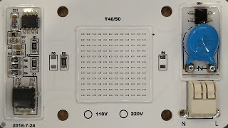
There's actual specs on these chips. Color Rendering Index:Ra85 Lumen: 980-1680LM
Color Temperature: Warm White 2800-3000K/ cold white 6000-6500K
Would this chip make a good DIY grow light ?
Better than a CFL, but grow lights have a spectrum tuned for growth. Purpley, no green in it (reflected by leaves). But you can't beat the price of these white ones.
Working pretty good here.
I've a couple of these warm whites, cooled with cheap CPU coolers, growing some "flowers". The plants love them, they don't care about the flicker. They last long with minimal heat when running with active cooling. Heat them first on a clothes iron to assist with soldering.
Thank you for this very nice detailed video, with the good zoomed hires printouts.
Really cool design. Just went on ebay and bought 8. One of each power and color temps. Thank you BigClive!
You should definitely get some proper tools to measure light emission, because your reviews are very interesting and getting the lm/W value would be the cherry on top.
Oh, and spectrometer to get the CRI :)
@@olafmarzocchi6194 chinese-electronics-products-tested.blogspot.com/p/dob-6040a-led-array-tested.html
Found this at some point.
I installed 5 of these in my shop today after seeing this video a couple of weeks ago. 120v in USA. Have no flicker at all. Will be installing a lot more. I like the 180 degree angle. Thanks for the video.
opennrgdotcom what did you do to cool them?
Mounted them on some 8" aluminum channel for now. Waiting to see how they last then I'll machine some fixtures for them. (2) 50w on 8" x 3" x 1 1/2" channel works good. Each 50w is mounted about 1 foot from the end. Have some 30w coming.
i mounted a 30w to a big aluminum cpu heat sink and that block gets quite warm. hard to find info on what is best to cool.
With the flicker and using for street lights, if you put each light on a separate phase of the the 3, would they flicker in sequence, as the sine wave is offset from each other?
Peter Grant I think so, it might not work perfectly but most of the time you'd have 2 arrays lit and one dark, cycling at 50hz.
running all 3 phases to the same light fixture sounds fun
+WineScrounger 100Hz actually.
I think I noticed a slight 3 phase 'chaser' effect in the stadium lights at the london olympics in the ultra slo mo playbacks. don't know what was actually in those fixtures, would guess that it wasn't LEDs though.
afaik 100Hz strobing isn't usually much of a problem unless you're operating rotating machinery when it can make things that are spinning look like they're stationary.
John Doe true, good spot
Its not easy to understand everything. BUT I LOVE IT! You help me with my depression.
Go on BigClive, you know you want to add a smoothing cap just to see how much better it runs
Thanks for these videos. You got me hooked on COB LEDs now. I bought a few of these 50 watt units myself, but wanted to improve efficiency while reducing heat. I was thinking of disabling one of the 5 driver chips to knock power down by 20%.
I'm a bit suspicious those chips are the same as in 5mm LEDs. I also have a couple of those LEDs and the chips are sooooo tiny! The 20W, 30W and 50W versions all seem to have the same chips (and the same number of them), this is weird.
seems a weird way to accomplish the end goal.. but that must mean they are just driving the chips must harder in the higher rated LEDs? probably not great for reliability or longevity in the higher rated units. Interesting tho.
@@nategaudette4228 if these are the YXO LEDs from Aliexpress, they have ~3year warranty
Awesome teardown. Didn't expect to see teardown below the LEDs ! NICE!
Can you put a capacitor on the output of your bridge rectifier to solve the flicker?
It would bring the voltage to 330v. DC (AC peak)
Yes, I have done so on a couple similar lights and they seem to be happy about it.
The flickering he is talking about is at 100Hz, its not a big problem on the human eye otherwise nobody would go to movies where the flickering is at 48 Hz, but its a its a major problem for tv camera. If you have put a few hundred nF cap on your circuit it does'nt made much of a difference but if you have a few 10's micro F its certainly flicker free and a lot brighter but not for long.
I'm using mine to shoot 1000+fps so the flicker was quite evident on camera.
I threw a 220uf in because it was what I had on hand but I don't see how it would cause the lights to fail early. It still draws the same average current as before and dissipates the same power unless the 80% duty cycle was used a "cool down" time.
A 220uF 400V is huge If you put it behind a rectifier it will keep the DC voltage at AC peak about 330V in this case supplying 4.5V to each LED well above its operating limits. What are the physical dimensions and the rated voltage of your cap?
I don't have a fraction of the electronics knowledge you have, but I have been experimenting with both the DCV LEDs, and the integrated power supply LEDs for use as shop lighting in my fab shop.
I have had NO problem whatsoever with flicker. I've tested everything from 20W to 150W integrated, (at 120vAC), and have been operating individual lighting implementations around the house, and in the shop, as trials.
The only problem I have had is with early failure in some 'full spectrum' integrated LEDs I built for my wife's plants. I enclosed full spectrum because the LEDs were actually so damn red, they made the entire house glow red during the day!
So much for full spectrum. I ended up mixing them with equal wattage cold whites at a ratio of 6 red to 4 cold whites to get a decent color that wouldn't make the plants continually what to flower.
The problem I've had is the lights are failing at about a 25-30% rate after two months of daily use.
Have you tested any of the integrated/driverless LEDs at 120vAC to see if the flicker still exists? Some of the eBay chips I've looked at have 110-250vAC, and some have either 120vAC or 240vAC inputs. I've tried some of each, at different wattages.
Something I was told, and verified, was some brands, and sellers on eBay sell a better quality LED; gold vs copper conductors, and copper vs aluminum bases. They are not more expensive, which is confusing. The early failure 'full spectrums' were not the gold/copper type. I've had no failures in the gold/copper LEDs. Any thoughts on this?
Thanks for your vids...
Could you explain power factor?
Simply Electronics AvE has a fairly good explanation of power factor, if you can find the video.
It tells you how much voltage and current are in sync. A pure resistive load always has 100% power factor (when the voltage is highest, the current is as well; when you are at half the max voltage you're also at half the max current aso. ; that's just Ohm's law). The more the shapes of the voltage curve and current curve differ (phase shift or general shape), the lower the power factor.
In a capacitive circuit you have a big inrush current as it's resistance at the start of the cycle approximates zero. As the voltage on the plates builds up the effective instantaneous resistance increases. IE the current leads the voltage. With an inductor because of magnetic field effects inducing back EMF (a reverse voltage) when the current is changing, then the current at the application of the voltage is at it's lowest and keeps rising until parasitic resistance limits current. IE Current lags behind voltage. In an AC circuit the lag and lead can be expressed as an angle and I think it is the sine of the angle that gives you the power factor number, as it is directly proportional to the ratio of real and apparent power. That said it's a long time since I studied this and most of what I work with is sub 1mW, and working in the frequency domain not time domain for analysis.
For regular folks, the power factor is essentially irrelevant, as the power company doesn't track that kind of stuff on your residential electricity bill, nor have a way to measure it with your regular residential meter. Industrial customers, with large banks of motors(inductors) like some sort of factory, probably do get that monitored and often put in capacitive banks to fix their power factors or get charged for the power company to do it. It is kind of an academic and engineering nerdy thing to worry about for most.
True in 90% for domestic users. However in some areas of Australia the domestic meters for people with large power banks and solar roofs do track power factor (partly to check that your system is putting power into the grid correctly). Also here in the UK all industrial units supplied with three phase have power factor tracking meters and you get fined if it is outside a set range.
I appreciated the action of your new cutting tool.
The reason the knife moves in such a way because when cutting plasterboard (Drywall) the blade gets covered in gypsum dust, which clogs the mechanism of a standard retractable knife. I use a folding lock knife.
Makes you wonder whether the next generation of these devices will include some form of on-board smoothing? As you note, electrolytics do have their own lifespan problems, but having an easy-to-change "Capacitor module" might be attractive to Municipal users? Alternatively the chips might be used to drive a thin phosphor layer with a modest decay profile, so eliminating a lot of the flicker? If there is the will to use these VERY simple devices, a way WILL be found to cost-effectively overcome their limitations.
I really enjoy the picture enlargements. Very helpful.
A Metcal or JBC iron with a fat tip would solder those with no problem.
+mikeselectricstuff Hey, steady on. This is supposed to be the trashiest electronic channel on TH-cam.
I agree with the other suggestions: the cheap Chinese hot air gun and some eBay special solder paste is the way to go. Or just the hot air gun to pre-heat the board before regular soldering, but I do love me some solder paste :D
JBC + unisolder is my way to go
Wouldn't it be possible to put an own rectifier and capacitor before the the L and N plates and just feed it an already pre-rectified and stable DC signal? I mean, there would be some more energy lost but I think that it should make the flickering stop. Or am I missing something here?
EDIT, In case someone reads this: Just after this video finished I saw there is a follow up video for this, where this exact option was talked about it turns out, that it is possible.
So....it's not a driverless LED but an LED with an integrated driver.
No shit sherlock
Well, i think of a driver as something standalone that alters incoming voltage to feed the need of an led. If the diodes themselves run on mains, then i suppose no, there are only safety measures like regulators and resistors from what I saw.
Might be totally wrong, thats just how i understood things.
I don't have a clue what you mean by most things you've said here. But this is extremely entertaining
Clive, have you tried shimming the gap between the heating element and tip? My chinese hakko ripoff can solder to these things with no troubles at all, and thats while they're stuck down to a heatsink.
Also curious, what happens to both power draw as well as thermals if you bridge an electrolytic across the bridge rectifier?
+Luke Den Hartog I've not tried shimming the iron yet. I considered the electrolytic. It would increase the voltage across the current limiting chips and probably cause then too go into thermal limiting mode.
bigclivedotcom Only one way to find out!
Perhaps two smoothed chips wired in serial? The voltage boost from the smoothing capacitor would be mitigated by splitting the AC voltage between two of these LED chips.
+bigclivedotcom Would love an update !
These would make a fantastic option if they could be smoothed.
Perhaps there will be a option if it works.
I've found that my Chinese "Weller" copy instant-heat iron works just fine on these boards. Seems to deliver the heat nice and quickly, with minimal heating of adjacent components.
Try putting a cap at the output of the chip, as regulator chip datasheet recommended. Might able lower the flicker but brightness will go low/high and add will add extra load to the chips. worth the try
Was anyone else hoping he'd try to power up the stripped carcass at the end?
Clive, use a small wire brush on the silicone, smd parts usually handle it fine.
I want to say soaking it in warm lacquer thinner (toluene) to make the silicone softer and less rubbery, but that doesn't work in all cases. it's nice when it works though.
Hey Clive, great videos, just ran today into them! Something crossed my mind - could you dimm it via the current limiting resistors at the CS pins?
the knife 16:25 is the Amtech S0282 Slide Unility Knife, by DK Tools LTD, is out of stock, looked it up out of curiosity 👀 using it as seen in this video requires you're a professional at taking things to bits.
I'm not an electrician, nor do I understand anything he is on about, why am I subscribed?
Keep watching, you'll learn something.
Dez Prez The soothing voice ;)
Gay Daleks and "personal massager" disassembly.
Neither am I, although I do enjoy tinkering with electronics. Keep watching, a lot of what I know I've learn't from this channel.
+Dez Prez Because you wanted to know what was in a USB butthole warmer and decided to stick around?
Excellent exam. I suggest a capacitor across the pulsating DC to eliminate the flicker.
A "Dremel" wire wheel brush, one of the brass bristle ones works pretty good and removing the silicone with out hindering the SM stuff.... Just messy to do...
+Dru Bradley I did indeed use a Dremel with brass brush to clean most of the PCB. It left it looking a bit grey though. I had to clean it up with acetone.
Roger that... I stand corrected.. I did realize actually how small the led's and that they would of never stood a chance... of surviving the the brush bristles...
I'm honestly satisfied that there's a led light out there for that price where the only problem is flicker- it could be worse, after all.
You use the word 'cheap' when we who deal with Chinese understand 'Westerners' are actually gdtting overcharged aka RIPPED OFF.
Hey Clive,
I was wondering if the flickering could be reduced or even stopped by using two of those driver less LEDs. One LED would be connected L1 on the top pad and N on the bottom pad. The second LED would be connected reversed.
With kind regards,
Tom
The calculator is too small to see
Very nice presentation. Please continue to do this type of exploring. I have learn a lot from your presentations. 😁 California, USA
Now you can make the Tick-welding video again.
They'll be ok if you have 3-phase power, just fit clusters of 3 in each fitting and put one LED across each phase. It won't stop the flickering 100% but it's a start.
Those sound like horrible Radio Frequency Interference generators, which would concern me as an amateur radio operator.
Nope. Operates at 100Hz, no fast edges or current spikes.
Now that you know what the circuit looks like I wonder if you could hack it to add a smoothing capacitor to help prevent or at least reduce the flicker?
It's 3:15am here in NZ... Who needs sleep, anyway?
Hello I have been running a 50 watt one for about twelve months it runs from a time clock for eight hours every night!👍
Ordered 5 x 20Watt 120V
Can't pass up that price.
Did you notice the odd pricing? 1 5-pack is higher than buying 5 x 1, $10,18 for a 5-pack, while $1.69 x 5 = $8.45
I've noticed a few sellers with "free" shipping start adding shipping if you order 3 or 4 or more of an item. Maybe the price jump is to account for the shipping weight of the multiple items.
Michael Tempsch i noticed that too
thank you for making this excellent video, you're on my daily list of favorite uploaders to watch! Electronics for dummies like me!
5:31 haunted lights?
Move out NOW Clive!
LMAO, didn't notice that until you pointed it out!
One of your best videos in a while! Thanks, Clive!
BigClive supporting the Chinese economy since 1979.
Glad you made this video. I have a bunch of these on order with plans to convert some outdoor 150w T-3 halogen fixtures. They only run about 15 minutes a day (while I let the dogs out at night), but will report lifespan either way.
thechosendude I would be hesitant to use such with animals as many animals should see the flicker as far more pronounced than we humans (many animals have much faster vision than we). To many animals these sorts of lights will literally look like a very bright strobe light which I would think to be very uncomfortable for them. But that is just my thoughts.
That is a point to consider. I have 1/2 watt nightlights in all the hallways of my house, which are poorly smoothed and kind of flickery, animals don't seem to matter. www.walmart.com/ip/Great-Value-10244-Great-Value-LED-Auto-Nitelite-4-Pack/24447283
I have a challenge for u..I went to my local pound shop and found a pack of 3 lighters for £1 ,they have leds on them.quite powerful.powerd by 3 small disk batteries..my challenge is could u make a small led grow lamp using these..
light it up
plus led grow lamps are very pricey I would love to try and make my own..for my tomato plants :)
the problem would be getting the right wavelength led's for growing, full-spectrum grow lights contain blue, green, red (which creates a white light or reddish light depending on the amount of green) and sometimes infrared (IR) and ultraviolet (UV)
No, I don't believe so because they require a high power output and mostly full spectrum of visible light. I have a bunch of Viparspectra 1200w and they have multiple different types of LEDs to cover the full spectrum. They aren't the best lights for flowering stages, but great for seedling and vegetative growth stage. I try to mix those LEDs with some 1000w HPS to give a full spectrum while also providing a good intensity for the limits to their photosynthesis. No real cheap way to get to growing cannabis or "tomatoes" unless you are doing it outdoors which you can't beat.
Dan ok cheers
I have that exact one! I got it a month ago. Mine was 10 cents less, and so far has worked well enough, albeit with some strobe. that was some great analysis ripping it all apart to see the traces. perhaps I'll go rip apart my 120V one and see what I can find. could you tack a large capacitor right across the +/- output on the bridge rectifier? considering how cheap these are and how expensive LED arrays are for streetlight modules are, someone could corner the streetlight industry with these. One 50W chip would be enough for most applications. perhaps two for more light and redundancy.
21:05 Based on datasheet’s “Typical Application” circuit, your drawn circuit schematic is wrong: Jumping Drain1 and Drain2 will cause a short circuit. Drain1 is basically DC- and Drain2 is DC+ to the leds (‘string).
5:10 -ish: just as a little aside, given most car engine blocks are aluminum and heatsink like crazy, it's possible, when an exhaust manifold stud breaks off in the block, to MIG weld a nut to it no problem, almost no matter what you crank your current setting to.
You're So Amazing, I'm not halfway through this Video , but Already Have Enjoyed From The Start.
Its Captivating like Bill Nye (the science guy
So thank U ,
i got the same led chip and the way i got the led to just glow wasnt using 2*1M ohm resistor, its way simpler than that. Just used those old power testers which have that carbon rod in them which limit the current and make the bulb in it glow, in series with one of the mains wire, it will dim down the led to same level to be able to take a photo. Good method if u dont have resistors or a variable power supply.
For my bench light I used three 30W 110V COBs in series to my 230Vac rectified and smoothed by a 50µF electrolytic cap. The do get quite warm but not really hot with a medium black heatsink passive cooling.
Hello I replaced a drive and a led with a driverless one about a week ago it runs every night for about eight hours and so far it’s been ok 👍
Thanks for the good video!
The parallel connection of all constant current drivers to drive the same load on their drains is interesting. I understand it will work if they have separate sampling resistors on their sources. But two drivers inside the same chip are connected not only at the drains but also at their sources. I am not quite sure how that will work well...
The cap for eliminating (or reducing?) the flickering will be quite big. My brief calculation shows that, in order to limit the ripple voltage on bridge output to 10V, a 220uF/200V cap is need for 110V/60Hz AC or 150uF/400V for 220V/50Hz AC.
I doubt the current is shared evenly by the two halves of each chip, but as the thermal regulation kicks in they may balance out.
The configuration is probably an afterthought for saving several resistors.
BTW, a popular usage of one half, as you saw (and were somewhat puzzled by @9:54 in your video:) in BP5132H datasheet, is to generate an enough "holding current" to fool SCR dimmer so that the dimmer can work reliably with LED.
what about adding the filter cap and using a resistor on the ac side to lower the voltage to get it to the proper operating spec?
I wonder will putting a capacitor (X2 or mains rated electrolytic) put in series with live connection will help with flicker. Or maybe going with external bridge rectifier and capacitor is the way to go?
Clive, i just happened to view this. I've watched allot of your videos. You really should be a teacher.
Nice investigation of these LEDs. I had wondered why they were so cheap.
I usually solder these by putting a little piece of solder on top, and then heat it slowly on a pan on the stove, till the solder starts to soften. At that point I transfer it to somewhere else and solders on wires with no issue at all.
Super easy.
I wonder if the 120v version has the same flicker. A slightly faster waveform should smooth it out a little bit, no?
Liked this vid a lot... though you teased us with the thermal regulation of those brightpower chips without testing it.
also wondered if they were supposed to be used in special fittings where contact was made by conductive wiper onto the board - looks like it'd be a pain in the ar$e to try replacing one in situ with a soldering iron - I'd guess access to these will be by cherrypicker or scaffolding tower in most typical applications.
Hello, do you have a video or directions on how to wire one of these up to stop the visible flickering? What can I connect to this before connecting it to AC wall outlet to stop it from flickering? Thanks
Hi clive i am really glad i found this channel, especially tgis very informative and educational video on this cob led. Lately i have been spending alot of time on these and ultimatly getting them burnt in quicker times, probably because i used higher wattage cod leds in lower wattage metal casing flood led lights, thanks for clearing many of my ambiguities and confusions regarding these.
P.s. i burnt 3 cobs even today, thats why found this channel due to. But i am really lucky to hace found your channel- subscribed.
They do push them hard. You could also use a low voltage LED COB panel with a power supply of your choice. I often use 20W or 50W drivers with 100W LEDs to under-run them.
How bad is the flicker to the naked eye? I'm tempted to get some of these and try and convert old 1500w halogen fittings with maybe 4 of these in 1 fitting could make for a cheep replacement for some floodlighting I have.
Hi very good video. did you try calculate the powerloses in these regulators? I think it's a crap construction reducing life time and waste a power. A proper driver can have efficiency better than 90% and add almost no heat
Very nice little chip. The scary thing is, I can VERY clearly remember the equivalent-wattage multichip LEDs coming on the market for a MUCH higher price than this, not that many years ago!. Next generation will have built-in smoothing, and they'll be just the same price . . . . . :-)
can you solder a small cap on the leads going into the LED array?
I have recently purchased these for around $1.75 for the 20watts but wow do they get hot, i suppose I just learned something, i plugged one in against a piece of aluminum din rail and i turned it off around 130c. I wasnt sure how long it could last like that. It did start dimming, but cooled down and got bright again like you said. I also recently tried a coffee cup heater for soldering under these aluminum pcbs from the thrift shop in town for a fiver
I shoulda mentioned i tried on the first one I got with a mapp torch and got it a little too warm and desoldered the FULL BRIDGE RECTIFIER on accident, i found out big clive style by doing a teardown after I broke it.
I understand about 10% of this!
Love your vids Clive!
Is there any way you can hook up several and cheaply shift the phase angle between them?
I can't find this information easy. Is a driver a current converter? Cant you run chips with AC 12, 24, 36 or 48 volt. Will that simplify the construction of the light and make it flicker less?
I've ordered a couple of 20w chips to put in existing housings and propose to put a 4.7/400 capacitor across the bridge. I understand that the dissipation of the LEDs will increase but I'm wondering if the zero ohms resistor should be replaced with a few ohms for anti-surge purposes..........
+Alan Powell Of the tests I did the best result was with the capacitor across the LEDs. I made a video showing how it was connected.
We had the same problem soldering or removing SMT parts onto a heat absorbing substrate at work. The way we dealt with it was to put the chassis on an industrial hot plate @ 250C just below the melting point of the solder we were using. A kitchen hot plate with an aluminum block on it would work if you kept the heat really low.
John Brandolini In electronics they actually have IR preheaters for the purpose of warming the backside of a circuit board in a controlled manner complete with attachable themocouples to precisely monitor the Board temperature at multiple points. They are extremely useful for dealing with multilayer circuit boards that have large internal ground or power planes. Such makes reworking such boards much easier as they can be a challenge to heat a given component to the melting point if hundreds of watts of heat are being wicked away faster than you can add heat. One can also use a high output soldering iron or gun for the same if you just need to quickly attach a couple of wires to a pad, but that brute force approach does not work well with temperature sensitive components with multiple pins where you have to be very mindful of peak temperature.
Ethan I worked for a defense aerospace company on integrated microwave assemblies. The chassis had very delicate controlled impedance boards which were easy to damage if you were ham handed with a soldering iron. Most of the parts were easily removed without heating the chassis; however; some of the MMICs had a large heat sink pad on them and they were the ones that needed the extra heat to remove. We referred to the pre-heaters as "hot plates" just for convenience. You know how it is in industry - sophisticated tools sometimes get cute nicknames. Our boss referred to cleaning the assemblies as "rinse and repeat". Those plates could almost reach the melting point of the solder used. Being a defense contractor the government didn't allow silver solder, only 63/37 led/tin having a melting point of 183 °C (361 °F) so the plate didn't have to be higher than about 70 °C to help reflow the solder. Still would give you a nasty burn if you weren't careful. I would imagine one could probably build a hot plate with a 100W incandescent bulb as a heat source that would be up to the task for hobby work. I'd do it except I have no need as of now.
I have the 20W version in 4 security lights with PIRs. The driverless led in each is marked 6040-F2525 (A1) and looks like that in the video. So far they fail after approx 1 year of use. Two types of failure: unit produces no light; and unit strobes at seemingly 10 Hz.
I wanted to see what happened if you put power to that after you took it to bits. Did you try? Was it pooched or did some of it light? Would have been something to try
Was the bridge rectifier in the drawing at 3:27 the wrong way round???
Yes. It's not uncommon for errors to appear on the data sheets for less popular chips.
Clive, look up "blue chip LED" , "flip chip LED", or "CSP LED" to see some of the new technologies. The flip chip does away with fragile bond wires.
Is this a visible flicker, or only visible on the camera? It seems to be at 100Hz, since it's full wave rectified, which is usually pretty much invisible.
Could you not add a smoothing capacitor to the rectifier to stop it flickering?
Very well done analysis.
When desiging similar things for the TX PAs for the mobile radio market, for soldering leads on it helps to heat the whole thing with an electric hot plate.
..
ALSO, It would be nice to actually see the current waveform on a scope. A 0.1 ohm resistor in series with the neutral side.
...
--
Regards
What would happen if you added an external diode and bulk capacitor and essentially ran the unit off DC? it might be a bit harder on the on board rectifier but I imagine it would work fine otherwise.