i am not electrical engineer but your lecture gave me idea how to design power control, i hope one day i will be with out going to school , thank you ! i follow your others too
U r the best bro, i'm a student of electronic circuits and I wanted to know how to design a zener regulator, because in my country they don't explain that, not even in yt, but thanks to u I've figured out how to do it.
Watched so many videos on this topic,but was unable to understand. This video cleared all my doubts. Thank you so much sir for such a great video 👌! Keep up the good work 😊👍!
I'm not sure about the voltage divider part. Remember that a voltage divider only works if the same amount of current flows through both resistors. If you have something connected between the resistors that is drawing current, you won't have the voltage that you planned for.
Thanks, I have a 300v zener regulator made from TWO 150v zeners in series. The resistor requirement for Imin is 300k (if one 300v zener were used). I am using TWO 150k resistors in series. Is it best to connect 150k across each (with a center connection) or to simply place one 300k resistor across the pair (no center connection)? THANKS AGAIN FOR ALL OF THE USEFUL VIDEOS!!!
I've seen a product that draws 200V, rectifies, voltage-divides to 12V and then regulates that to 5V with zener diode. To power a microcontroller. Super scary, but went through certification and works
...one more thing: For the shown zener parameters, why not choose a max. series resistor via I=0.250w/(24v-12v)=20.8mA, thus: R~12v/20.8mA = ~577 Ohm or greater? My main reason for asking: my load is not a resistor, but a 0.5uF capacitor that is charged/discharged (from an 800v supply to 400v) at about 75Hz by the zener output. My series zeners are TWO 200v @10W each. THANKS VERY MUCH!!! Thumbs UP and subscribed!
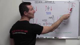
The values in my circuit are pretty much arbitrary, so there is no particular reason that I choose 470 Ohm. The exercise was about assuming 24V source, 12V Zener and 470 Ohm series resistor and then figuring out the rest. In your example, I guess you are looking at situations when the capacitor is fully charged, so no current goes to the load. I think then it makes sense to re-design to put the larger resistor in series to protect the Zener from too much current.
What if you’re just wanting to ensure that an input pin is protected? I designed a converter that takes +/-12V range and converts to 0-3V3V range. I don’t want to exceed 3.3v but When I add a 3.3v zener my output doesn’t reach 3.3v (only gets to about 2.6v when 12v is applied)
I am lost, can you help please??? I have a variable source between 0 and 16 volt dc and need to power a 3 volt 20ma LED PLEASE help and send me a circuit diagram useing a 3volt zener on this variable source, I understand that the LED will not light up until the voltage exceeds 4 volts or there about but I do not want it ot the zener to burn out when the voltage rises to 16 volt, I also want the LED to remain at a constant brightness from 4 volts to 16 volts U
If there are 2 Zener diodes in series (with the same orientation) then the total zener voltage is the sum of the Zener voltages of the 2 diodes. The knee current will be the greater of the knee currents of the 2 diodes and the max current will be the lesser of the max currents of the two diodes.
If the load resistor, (RL) in this case, is removed from the circuit, will it burn up?? If so can a permanent ~2571 ohm resistor be soldered across the zener as a safety measure if you do not use less than a 480 ohm load?
Can equivalent zener diodes be connected in parallel (2 or 3) if 'balancing' resistors are properly used to handle small voltage differences? Thanks much... --dALE
In theory yes, but there is always the risk of having unbalanced branches. It's generally better if you can find one Zener that will handle your current needs.
A diode operates in forward bias, VT = 0.026 V. For Vd= 0.600 , the current Id = 1 mA. For Vd=0.680V, the current Id=10 mA. Determine the values of Is and n.
you have to apply KVL to find the voltage across first resistor Vr=Vs-Vz Vr=24-12=12v across the R1 then you apply omh's law as he did, but he did both steppes by one Is=Vr/R1 because the current through the R1 same as source (R1 in series with the source) Is=12/470=25,5 mA
@@ElectronXLab Bro my question is like"design a voltage regulator that will maintain an output voltage of 20v across a 1-kohm load with an imput that will vary between 30v and 50v.that is determine the proper value of Rs and the maximum current Izm"i have got the value of Rs 500ohm for Vi min=30V,but i cant understand about this Izm,there is also not given Pmax
@@arifahmed2492 Okay, it sounds like you're not worried about the ratings of the diode itself, so the max zener current is just based on the current that will be through the Zener diode when the voltage source is at 50V. You've already calculated the current through the 1k load and used that to figure out your Rs value. Now figure out how much current through Rs when the voltage source is at 50V, subtract the current that is going to the load and whatever is leftover is the maximum current that will go through the Zener.
When regulating: P=(I^2)*R OR P=(V^2)/R. P=12v^2/470 ohm = 0.3W. and I=V/R=12v/470 ohm = 0.03Amps. So P=(0.03^2)*470ohm = 0.3W. SO: by two different methods...P=0.3W. Since 1/4 W =0.25 W, a 1/4 W resistor will overheat, therefore use at least a 1/2 Watt 470 ohm resistor.
minimum that much required to keep the diode in conduction other wise zen er wont regulate, and out put will fluctuate please subscribe my channel to know more


![[LIVE] : ONE ลุมพินี 83 วันนี้!! คู่เอก "พันฤทธิ์ vs ซุปเปอร์บอล วันของโอม MBK"](http://i.ytimg.com/vi/1b4pkKHa_Fk/mqdefault.jpg)


Still doesn't coincide with a general case or formula, but still the best video I have found. Thank You
i am not electrical engineer but your lecture gave me idea how to design power control, i hope one day i will be with out going to school , thank you ! i follow your others too
Thanks for your comments. Good luck with your projects!
U r the best bro, i'm a student of electronic circuits and I wanted to know how to design a zener regulator, because in my country they don't explain that, not even in yt, but thanks to u I've figured out how to do it.
Thanks a lot sir, I've been finding these for weeks! Finally, I can understand what's happening with these zener diodes
Watched so many videos on this topic,but was unable to understand. This video cleared all my doubts.
Thank you so much sir for such a great video 👌!
Keep up the good work 😊👍!
A real life explanation, I finally understand how a zener diode regulates voltage and within what range, thanks a bunch !
Your teaching was great
Just the thing I was looking for. Thanks sir.
Excellent explanation
Thanks,
I am using a zener to charge a small capacitor (
I'm not sure about the voltage divider part. Remember that a voltage divider only works if the same amount of current flows through both resistors. If you have something connected between the resistors that is drawing current, you won't have the voltage that you planned for.
Thanks,
I have a 300v zener regulator made from TWO 150v zeners in series. The resistor requirement for Imin is 300k (if one 300v zener were used). I am using TWO 150k resistors in series. Is it best to connect 150k across each (with a center connection) or to simply place one 300k resistor across the pair (no center connection)?
THANKS AGAIN FOR ALL OF THE USEFUL VIDEOS!!!
just what i needed, thanks
I've seen a product that draws 200V, rectifies, voltage-divides to 12V and then regulates that to 5V with zener diode. To power a microcontroller. Super scary, but went through certification and works
I think I've seen that before
...one more thing: For the shown zener parameters, why not choose a max. series resistor via I=0.250w/(24v-12v)=20.8mA, thus: R~12v/20.8mA = ~577 Ohm or greater? My main reason for asking: my load is not a resistor, but a 0.5uF capacitor that is charged/discharged (from an 800v supply to 400v) at about 75Hz by the zener output. My series zeners are TWO 200v @10W each.
THANKS VERY MUCH!!! Thumbs UP and subscribed!
The values in my circuit are pretty much arbitrary, so there is no particular reason that I choose 470 Ohm. The exercise was about assuming 24V source, 12V Zener and 470 Ohm series resistor and then figuring out the rest. In your example, I guess you are looking at situations when the capacitor is fully charged, so no current goes to the load. I think then it makes sense to re-design to put the larger resistor in series to protect the Zener from too much current.
I thank you you have me glued to my seat I do not even want to move to go to the
What if you’re just wanting to ensure that an input pin is protected? I designed a converter that takes +/-12V range and converts to 0-3V3V range. I don’t want to exceed 3.3v but When I add a 3.3v zener my output doesn’t reach 3.3v (only gets to about 2.6v when 12v is applied)
Can typical zener diodes handle higher frequency inputs (in the kHz range)? I can't find any data on this.
This video is life saving.
Super clear explanation, thank you very much !
I am lost, can you help please???
I have a variable source between 0 and 16 volt dc and need to power a 3 volt 20ma LED
PLEASE help and send me a circuit diagram useing a 3volt zener on this variable source, I understand that the LED will not light up until the voltage exceeds 4 volts or there about but I do not want it ot the zener to burn out when the voltage rises to 16 volt, I also want the LED to remain at a constant brightness from 4 volts to 16 volts
U
great help but what if there are 2 Zener diodes?
If there are 2 Zener diodes in series (with the same orientation) then the total zener voltage is the sum of the Zener voltages of the 2 diodes. The knee current will be the greater of the knee currents of the 2 diodes and the max current will be the lesser of the max currents of the two diodes.
If the load resistor, (RL) in this case, is removed from the circuit, will it burn up?? If so can a permanent ~2571 ohm resistor be soldered across the zener as a safety measure if you do not use less than a 480 ohm load?
no need .use a zener of o.5 w or more
Can equivalent zener diodes be connected in parallel (2 or 3) if 'balancing' resistors are properly used to handle small voltage differences?
Thanks much...
--dALE
In theory yes, but there is always the risk of having unbalanced branches. It's generally better if you can find one Zener that will handle your current needs.
A diode operates in forward bias, VT = 0.026 V. For Vd= 0.600 , the current Id = 1 mA. For Vd=0.680V, the current Id=10 mA. Determine the values of Is and n.
the las 20 seconds is my favorite part
I had to re-watch to remind myself what I put there. It's my own joke, but it made me laugh
Can 27v zener diode take up to 24v DC?
If yes, what value of resistor can I use across it?
Pls help
Herding electrons since 1994. How many do you have? And do you have enough storage space?
Why did you choose a 470 ohm resistor?
why min. load current is 4.67 instead of 4.7???
only this issue.....otherwise very helpful ...thanks a bunch
Wheather any capacitor is required after zenner ?
thanks sir for your good explanation
very well explained
Thank you so much sir.
You're most welcome
Great content. Really helped.
Why can IL=25.5mA-0.5mA I don't know 25.5mA How does it come out??
you have to apply KVL to find the voltage across first resistor
Vr=Vs-Vz
Vr=24-12=12v across the R1
then you apply omh's law as he did, but he did both steppes by one
Is=Vr/R1 because the current through the R1 same as source (R1 in series with the source)
Is=12/470=25,5 mA
@@fadihanna1545 nice explanation bro really appreciate that.
What is the rule for Vi min and Vi max,i need to find Izmax
Izmax will be based on the maximum power that can be dissipated by the diode and the zener voltage. Izmax = Pmax/Vz.
@@ElectronXLab Bro my question is like"design a voltage regulator that will maintain an output voltage of 20v across a 1-kohm load with an imput that will vary between 30v and 50v.that is determine the proper value of Rs and the maximum current Izm"i have got the value of Rs 500ohm for Vi min=30V,but i cant understand about this Izm,there is also not given Pmax
@@arifahmed2492 Okay, it sounds like you're not worried about the ratings of the diode itself, so the max zener current is just based on the current that will be through the Zener diode when the voltage source is at 50V. You've already calculated the current through the 1k load and used that to figure out your Rs value. Now figure out how much current through Rs when the voltage source is at 50V, subtract the current that is going to the load and whatever is leftover is the maximum current that will go through the Zener.
@@ElectronXLab sir,i am still suffering to calculate this math,do you please explain it for me if you dont mind?
@@ElectronXLab i have got the solution now,R=0.5kohm and Izmax=40mA.I hope it is all right,tnx for your suggession
How do i go about solving for iL with known Vz and known load but known Vs? thanks
If you know Vz, IL is easy to find since Vz=VL. IL = Vz/RL. The caveat is to make sure there is enough current from the source
@@ElectronXLab thanks, it actually came to me like 5 minutes after watching your video. great video btw
thanks a lot.
Awesome
thank you man youre great
What is the correct watt for 470 ohm resistance!
When regulating: P=(I^2)*R OR P=(V^2)/R. P=12v^2/470 ohm = 0.3W. and I=V/R=12v/470 ohm = 0.03Amps. So P=(0.03^2)*470ohm = 0.3W. SO: by two different methods...P=0.3W. Since 1/4 W =0.25 W, a 1/4 W resistor will overheat, therefore use at least a 1/2 Watt 470 ohm resistor.
where did the 0.5 come from?
Is it fixed?
The Iz(min) is fixed at 0.5mA. It's the minimum current that the diode needs in order to put the diode into it's regulation mode.
@@ElectronXLab is it fixed due to problem Sir or is it a fixed value due to the type of diode?
@@ivanrasheedranchez9155 Both. It will be fixed due to the type of diode and I arbitrarily picked a value of 0.5mA for the diode in the problem.
@@ElectronXLab Thank you sir!
thank you
You're welcome
thanks
Great
Where is that 0.5mA figure coming from
minimum that much required to keep the diode in conduction other wise zen er wont regulate, and out put will fluctuate please subscribe my channel to know more
Wow
i love you
7:12 LOL
You keep saying 12 volts...just make it 12 volts maybe
I'm the only one seeing this?
Ah it's the max voltage Vz
Pardon me folks I should actually watch the video
🕉️🚩🚩🚩
जय श्री राम