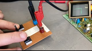
#88: Cheap and simple TDR using an oscilloscope and 74AC14 Schmitt Trigger Inverter

แชร์
ฝัง
  • เผยแพร่เมื่อ 19 มิ.ย. 2024
  • This video is a follow on from my previous video that discussed how to measure the length and impedance of coax using an oscilloscope and an pulse generator. This previous video goes into more of the theory and the different measurements you can make. It can be found here:
    • #37: Use a scope to me...
    However, this video showed the use of a pulse or function generator as the signal source. The problem is that most inexpensive generators won't have a fast enough risetime to be able to resolve shorter cables or finer precision in the measured length. This video shows a very inexpensive circuit that you can build that has a very fast rising/falling edge speed, making it easy to more precisely measure the cables.
    It is based on a 74AC14 Schmitt Trigger Inverter chip and a handful of passive components. One of the six inverters is used as an oscillator which drives the remaining 5 inverters in parallel to drive the coax under test.
    More detail regarding the Schmitt Trigger circuit can be found in the video uploaded immediately prior to this video:
    • #87: Schmitt Trigger O...
    This video is shot in HD
  • วิทยาศาสตร์และเทคโนโลยี

ความคิดเห็น • 357

  • @jeffreyyoung4104
    @jeffreyyoung4104 ปีที่แล้ว +11

    I built the TDR circuit from QST years ago, and I used it at work with the better scopes to check coaxes on the reel, and the boss was so impressed, he went out and spent a ton of money on a box that had a microprocessor that did the math for you. But it never worked better, nor was it built under $5.00!

  • @richardneel6953
    @richardneel6953 ปีที่แล้ว +9

    Makes my heart happy to see someone using an RPN calculator. I get the video is almost 10 years old, but had to comment on the lost art. :)
    Had to comment that this technology is also used in optical telecommunications networks, but is called OTDR (O for optical - of course). We use it every day to find optical fiber cuts/damage.

    • @larrybud
      @larrybud ปีที่แล้ว

      I was trying to figure the use case for this, and a broken wire or cable is perfect!

    • @DM-fz3ly
      @DM-fz3ly 4 หลายเดือนก่อน

      "RealCalc" for android is an excellent RPN

    • @petermikus2363
      @petermikus2363 3 หลายเดือนก่อน

      I've got a HP 50g i use at school in RPN mode (17 btw)

  • @Vintage_USA_Tech
    @Vintage_USA_Tech 11 ปีที่แล้ว +9

    in the late 70s I couldn't wait to crack open my new Popular Electronics magazine just to build the next new project in what seemed to be a magical time for electronics hobbyist and home inventors. And I have to say everyone of your videos brings that magic back X10 in a way we could only have dreamed of in the 70s. Thanks a million for all the great videos.

  • @billjones2271
    @billjones2271 8 ปีที่แล้ว +15

    Suddenly my 40-meter yagi had a high SWR. I used one of these little TDR circuits and determined the exact location of the problem. I'm sold. Thanks! 73 de K8CU

    • @w2aew
      @w2aew  8 ปีที่แล้ว +5

      +Bill Jones That's great to hear - glad it worked for you!

  • @christheother9088
    @christheother9088 8 ปีที่แล้ว +5

    Man, the precision of that setup is remarkable.

  • @ronaldlijs
    @ronaldlijs 11 ปีที่แล้ว +1

    There is excellence in how you explain/present your videos, PLEASE PLEASE keep them coming, this is great stuff!

  • @MaqsoodAlamShafiq
    @MaqsoodAlamShafiq 3 ปีที่แล้ว

    It is indeed a pleasure watching you explaining tricks of electronics trade the conventional way using vintage tools. Love it.

  • @Lskaggs63
    @Lskaggs63 10 ปีที่แล้ว +6

    Great idea and excellent circuit! When I worked for the Navy I used Pulse Generators that cost hundreds of thousands of dollars, your circuit is outstanding, I have got to build one for myself. Thanks!

  • @nemanjatodorovic2803
    @nemanjatodorovic2803 11 ปีที่แล้ว +9

    You have the best tutorials I've ever seen! honestly! thank you!

  • @norbs
    @norbs 10 ปีที่แล้ว +3

    Man, you are a genius! I just build the circuit and it works great, I measured a 3m cable and it gave a result of 3.003m. I used the CD74AC14M96, SOIC-14 version from texas.

  • @scottgilson3247
    @scottgilson3247 2 ปีที่แล้ว +2

    Thanks for a great video! I built it to find a break in a Romex power cable. Got 1.2ns/foot. Used a 74LS14 as that was all I had available. Needed to change the 6.8 kOhm to 1 kOhm to get it to oscillate.

  • @stevejagger8602
    @stevejagger8602 ปีที่แล้ว +1

    This is a subject I have had an interest in for some long time.
    Thank you for the clear explanation.

  • @11zekim
    @11zekim 11 ปีที่แล้ว +7

    Great idea, thanks for posting! There should really be a hex inverter cookbook!
    Teachable suggestions: in addition to open-end, you could also show terminating the coax properly, and then shorting it. Many students find the result counterintuitive.
    Even cooler, show the far end voltage (with a low-C probe) on your second scope channel!

  • @BillySugger1965
    @BillySugger1965 7 หลายเดือนก่อน +1

    Love it! I’ve built a few 80:20 instruments like this to get at least 80% of the functionality at way less than 20% of the cost and complexity of a commercial instrument.

    • @w2aew
      @w2aew  7 หลายเดือนก่อน +1

      Search my channel for the super-simple TDR. If you have a digital or storage scope, you can do this with nothing more than a battery, a resistor and a couple of clip leads...

  • @PeterWMeek
    @PeterWMeek 8 ปีที่แล้ว +3

    Great way to determine the impedance of an unknown bit of coax. (video #37)
    You can also calculate the VF for an unknown bit of coax. Take a measured length and back-calculate what the VF *must* be to get the measured delay from a known length.
    Thumbs up for bothe the #37 and #88 videos. (this comment posted on both videos)

    • @w2aew
      @w2aew  8 ปีที่แล้ว +2

      +Peter W. Meek I did a video on that too (measuring velocity factor), exactly as you've stated.
      th-cam.com/video/TpIIftvQPFM/w-d-xo.html

  • @purza95
    @purza95 8 ปีที่แล้ว +2

    Again, I am in awe! Great instructional videos! I've learned more here in an hour than I've been able to over a decade of reading. Thanks again.

  • @famossfla
    @famossfla 10 ปีที่แล้ว

    Once again a great demonstration. I'll have to set this up and try it. Thanks....

  • @msk19991
    @msk19991 11 ปีที่แล้ว

    I really appreciate the effort & time you put into making these tutorials, many thanks & god bless.

  • @g0fvt
    @g0fvt 10 ปีที่แล้ว

    Yet another great video, when wanting to make phasing lines at home I have used a signal generator, receiver and tee piece, trimming the cable for maximum signal "suck out" using the open circuit 1/4 wave...
    Your little circuit is a much more flexible solution.. should run for a while on 3 aa cells.

  • @lingcod91
    @lingcod91 7 ปีที่แล้ว

    We had a manufactured TDR which was invaluable for figuring the length of cable on a spool. Very good video showing a low cost way of doing the same thing. Not as fast, but you're not selling to a client either.

  • @johnbrandolini2915
    @johnbrandolini2915 7 ปีที่แล้ว +1

    Alan, thanks for the great video. It prompted me to build my own 9 volt powered time base generator based on a 10 MHz clock oscillator. I wanted something a little more versatile so I I'm using 2 74HCT74 DFlops to give me a range from 10 MHz to 625 KHz. I tried it at the lowest frequency with an ~ 5' unterminated cable and lo and behold it worked! I got a 17 nanosec delay which after calculating the length equaled 66.1 inches which was pretty close to the length of the cable I made. Isn't math and physics great!

    • @w2aew
      @w2aew  7 ปีที่แล้ว

      Cool!

  • @flanlemonjello
    @flanlemonjello 11 ปีที่แล้ว +1

    I've been watching Greg Durgin's transmission line theory course.. and now this! I'm in youtubopia! Thanks for another great video!

  • @CodfishCatfish
    @CodfishCatfish 10 ปีที่แล้ว

    That's really great to hear. I can't wait to see it if you ever make a video on it. Always a pleasure watching your videos and have built many of your test devices demonstrated in your videos. Thanks and keep up the sterling work. 73 Spence de M0STO

  • @Dustycircuit
    @Dustycircuit 6 ปีที่แล้ว

    Awesome casual Friday project!

  • @kg6tgr
    @kg6tgr 11 ปีที่แล้ว

    This video is extremely detailed and informative. Thanks for the post and keep posting.

  • @M6MRP
    @M6MRP 11 ปีที่แล้ว

    Once again well presented, very clever and cheap as chips to build, going to have lots of fun with my scope after watching your videos.
    keep up the good work
    73
    Phil

  • @TheCrazyStudent
    @TheCrazyStudent 11 ปีที่แล้ว

    Thank you for uploading in high def. And thanks for all your great videos. Keep up the good work. Btw, it would be great to se a follow up video of how this applies to other types of cables, and not just coax.

  • @Roger-pw3zz
    @Roger-pw3zz 3 ปีที่แล้ว +1

    Very helpful and beautifully presented. Thank you!

  • @danielolivera2618
    @danielolivera2618 3 ปีที่แล้ว

    thank you so much. the best video on reflectometer yet.

  • @rlamb51
    @rlamb51 11 ปีที่แล้ว

    Outstanding videos. I've only watched a couple now but they are very well done and interesting.

  • @mrcrud5
    @mrcrud5 10 ปีที่แล้ว +5

    Lovin the nixie tube frequency counter!

  • @hoffm426
    @hoffm426 2 ปีที่แล้ว +1

    Great job and easy to follow.

  • @kd1s
    @kd1s 11 ปีที่แล้ว

    Pretty cool video! And I love the RPN calculator. My first calculator was a Toshiba RPN with vacuum fluorescent display.

  • @PeterGagen
    @PeterGagen 10 ปีที่แล้ว +1

    Thanks for this. This is very helpful. It has given me ideas that I will be trying out

  • @yoramstein
    @yoramstein 8 ปีที่แล้ว

    Another great video of yours Alan. Thanks.

  • @carmelpule6954
    @carmelpule6954 9 ปีที่แล้ว

    Excellent presentation, my congratulations.

  • @fourfortyroadrunner
    @fourfortyroadrunner 11 ปีที่แล้ว

    Good job, AEW. Wish I had this talent for good legible instruction

  • @hackercop
    @hackercop 2 ปีที่แล้ว

    This was a really great video, I want to build one of these. thanks

  • @fabiotrevisan8922
    @fabiotrevisan8922 7 ปีที่แล้ว +6

    Great video Allan!
    I`m just re watching your video on this TDR pulse generator, which I first watched maybe 2 years ago, which inspired me to build it re purposed for something else.
    Two years ago I was looking for something that I could use as a fixture to calibrate a 60Mhz oscilloscope's step response. A "poor men's" approach for someone who didn't have a fast edge pulse generator (

    • @absurdengineering
      @absurdengineering 2 ปีที่แล้ว +1

      The trick with AC14 is to use 2/6ths of the chip as a cable driver, and the 4/6ths to lower the impedance of the power delivery to the chip. How? Feed “0” to 2 inverters and connect their outputs directly to VCC. Feed “1” to another 2 inverters and connect their outputs directly to GND. You’re now driving the on-chip power distribution through two extra pins per rail. It improves things quite a bit. You need more chips then of course, and their inputs and outputs must be respectively equidistant. So the oscillator must connect to all the inputs via a wire/trace of identical delay. Same goes for the outputs connecting through the resistors to the BNC. With some extra care that chip can drive just under 2ns edges, extremely cleanly.

    • @user-zc8sd8jx8s
      @user-zc8sd8jx8s ปีที่แล้ว

      @@absurdengineering wow, what a trick, live and learn. i suppose it should also apply to other chips as well? for example the AC00 that I used in a similar little project.

    • @absurdengineering
      @absurdengineering ปีที่แล้ว +1

      @@user-zc8sd8jx8s Yes. But always measure stuff and use an objective way to see the difference, like capturing a reference trace on the scope using a straightforward circuit, and then observing how the “improved” circuit’s output compares to the reference trace. It should be done using the intended load too, ie. 50 or 75 ohms or whatnot, properly terminated.

  • @x86cowboy
    @x86cowboy 11 ปีที่แล้ว

    A video lab tour of your equipment / gadgets would be interesting!

  • @TheBdd4
    @TheBdd4 11 ปีที่แล้ว

    Thanks for your excellent video. I have been thinking about how to design a fast rise pulse generator for an experimental circuit I am working on. Your video helps immensley. I want to generate just one fast rise pulse so I have designed a debounced pulse generator that works with both TTL and 4000 CMOS - up to 18VDC supply. I am going to build your circuit.

  • @Pwaak
    @Pwaak 11 ปีที่แล้ว

    Great project and learning opportunity! Thank You!

  • @raffyturc
    @raffyturc 5 ปีที่แล้ว

    Ive read about this on textbooks(TDR). Nothing more, up until I see an actual 👍 thanks

  • @ozgemmo3445
    @ozgemmo3445 9 ปีที่แล้ว +1

    Hi Alan - this is a very late comment to your TDR video (its now 2/01/2015); as a total newbee to this medium firstly let me congratulate you on your perfection, schematics and absolute clarity you present these details. As a semi-retired scientist (analytical chemist, geologist & gemmologist) who is now getting back into main stream electronics after a 45 year break - you are truly a breath of fresh air!!!
    I have read every reply since when you first posted this video and have not been able to get any details on your "decoupling capacitor" used - I have searched in vain on the internet the numbers that are visible on the yellow square plastic cap; viz '2073G, L1104 & E8515', and have drawn a total blank!!!
    Would it be possible for you to provide this cap details, its type and how you have connected it to your TDR apparatus as this is not at all clear in the video???
    Also explaining what the 'decoupling cap' is actually doing to the voltage supply (a wild guess on my part, without knowing, is that it is removing or reducing to a very low level any AC ripple on the incoming DC voltage)???
    Further, do you have a complete circuit diagram - including the decoupling cap - for your very cleaver piece of kit?
    I am wishing to build your TDR as I can see this will be very instrumental in teaching me how to use my very new 100MHz digital scope as well as providing a very practical application for it.
    If I may comment to the very few rude people who criticise your use of imperial units - I would say get a calculator and do the maths yourself if this is an issue for you; we all use what is or native tongue and what metrics we are totally familiar with! To the few who have complained about you saying "OK" every sentence - to them I say; "yes it can be distracting and break one's concentration when a viewer is hanging on your every word", but to them I say "suck it up" and move on if you can't really appreciate all that Alan is saying and presenting!!! Your adverse comments demean this guy and all the good he is doing for us very new and perhaps not so new 'Newbees'!
    Keep up the excellent work, mate!
    Cheers, Ian (from Gippsland in Victoria, Australia)

    • @ruhnet
      @ruhnet ปีที่แล้ว

      😅 you probably already know this by now, but a “decoupling capacitor” is in 99% of cases generally any capacitor with a value of between 0.001uF and 0.1uF. And you are correct in that it’s purpose it to remove any high frequency interference (you could call it ripple but generally that refers to lower frequency variations) on the DC power.

  • @Radiowild
    @Radiowild 11 ปีที่แล้ว

    Great explaination as always!

  • @robertstephens5163
    @robertstephens5163 5 ปีที่แล้ว

    Nice presentation and nice build technique minimizing lead inductances. I really wish you had closed with a look at the reflectometer trace as a 50 ohm termination was placed on the far end of the 5 foot cable and also a short circuit. Nice scope!

    • @w2aew
      @w2aew  5 ปีที่แล้ว

      I show the effect of various impedances (including matched impedance) at the tail end of this video:
      th-cam.com/video/Il_eju4D_TM/w-d-xo.html

  • @thecombatengineer7069
    @thecombatengineer7069 5 ปีที่แล้ว

    binge watching all the circuit tutorials, trying to remember to like and comment on each as well. Noticed you do the "okay" a lot but its not distracting. the content is great

  • @LikeToMakeTools
    @LikeToMakeTools 10 ปีที่แล้ว

    Nice idea! Thanks for sharing!

  • @jaak68
    @jaak68 11 ปีที่แล้ว

    As always, great work! Do you think that equal path lengths on the inputs and outputs might reduce the ringing slightly? And surface mount resistors to reduce parasitic C?

  • @TzOk
    @TzOk 4 หลายเดือนก่อน +1

    It works not only for coax, I've just used this method to find a cut wire on a 40m extension cord. It was spot on.

    • @simonfencing
      @simonfencing 3 หลายเดือนก่อน

      Did you have to use one of the other wires as ground/shield?

    • @TzOk
      @TzOk 3 หลายเดือนก่อน

      @@simonfencingI was using another wire as a reference wire, but I'm not sure if it was crucial.

  • @jrallen870
    @jrallen870 11 ปีที่แล้ว

    Another great video. Did you require all the paralleled triggers for power or just used them because they were available on the chip?

  • @keithlillie7751
    @keithlillie7751 10 ปีที่แล้ว

    Great circuit! Now if I only had an oscilloscope!

  • @johnbrandolini2915
    @johnbrandolini2915 7 ปีที่แล้ว

    Hey Alan, wanna hear a good one. The 74AC14 is discontinued according to Jameco Electronics. I used the HCT14 which has a rise time of 5 usecs. Just for shits and grins I tried measuring cables shorter than 4 ft and it didn't work. But... that's what they make tape measures for. :-D I use Jameco for most of my parts purchases since they give free shipping for orders over $25. Usually I'm lucky if I'm under $50.

  • @CodfishCatfish
    @CodfishCatfish 10 ปีที่แล้ว

    Hi Alan, Great video's as ever. Do you think it is possible to build a TDR into a box to go portable. I doubt an Arduino is powerful enough to act as a sort of portable scope however a Spartan FPGA and ADC might and use the Arduino as an input for say VF to do the conversion and output to an LCD the length. Beats paying the megabucks for a portable TDR.

  • @douro20
    @douro20 9 ปีที่แล้ว

    I saw a circuit which uses a single-transistor avalanche pulse generator. It needs a high-voltage power supply to work, but the advantage is that you can fit the entire pulse generator inside of a single BNC connector.

  • @SimpleEnough2k9
    @SimpleEnough2k9 10 ปีที่แล้ว

    Hi Alan. I've seen a similar design to yours, where there is a "RD" (resistor/diode in serie) in parallel with the feedback resistor, in the actual design, the 6.8k. What would be the purpose of such feedback "network" ?

  • @ujjainia123
    @ujjainia123 ปีที่แล้ว

    very useful idea . thanks for share . 🙏

  • @GaRbAllZ
    @GaRbAllZ 11 ปีที่แล้ว

    Great video Alan.
    How long a cable can this device test?

  • @alexverias7104
    @alexverias7104 8 ปีที่แล้ว

    very nice
    cheap,easy and effective

  • @paulpkae
    @paulpkae 4 ปีที่แล้ว +1

    These are very informative videos and have answered a lot of age old questions in my head. Many thanks. Can I ask why you chose to utilize the remaining five schmitt triggers in parallel, rather than just add 50ohm resistor to a single schmitt output?

    • @w2aew
      @w2aew  4 ปีที่แล้ว +2

      Mainly to get more drive capability since a single stage struggles to drive a low impedance load like this.

  • @valordk
    @valordk 9 ปีที่แล้ว

    Definitely helpful. Thanks!

  • @ronaldlijs
    @ronaldlijs 11 ปีที่แล้ว

    Oh, love the HD too!

  • @VintageProjectDE
    @VintageProjectDE 8 ปีที่แล้ว

    Really amazing tutorial.
    I built this on a breadboard with a 74HC14N and used a 10k multi-turn trimpot for a range of ~3kHz up to 500kHz.
    Pretty nice to see those steep edges on screen. :o)
    (I did this to test my new old scope. The 10 MHz bandwidth seems to filter most of the ringing away, though)

    • @w2aew
      @w2aew  8 ปีที่แล้ว +1

      +Thilo Niewoehner I'm sure it looks really nice and clean with a 10MHz scope!

    • @VintageProjectDE
      @VintageProjectDE 8 ปีที่แล้ว

      *****​ Absolutely. As I said, most of the ringing is gone except for a 0.5 V overshoot (at 5 V supply).
      And the edge appears really steep, while the fastest timebase on that scope is 0.5 us/div (actually 0.1 us with x5 zoom)
      I'll check this once more next weekend when I have the remaining parts for the similar 555 pulse circuit with adjustable duty cycle.
      Then I can also compare to my 100 MHz DSO.
      It's quite some fun to play with analogue circuits every now and then :-)

    • @VintageProjectDE
      @VintageProjectDE 8 ปีที่แล้ว

      If I get to it, I'll try to take some pics and show them together with the Telequipment D61a scope over on eevblog.com

  • @wa4aos
    @wa4aos 11 ปีที่แล้ว

    Another fine video.
    Years back when I worked for DEC, we lugged a 50 pound TDR whenever we had Ethernet problems that were not resolved by standard troubleshooting methods. Often we would find a broken piece of coax in a plant or open terminators. Sometimes we would find transceivers attached to the coax where the input went low resistance and loaded the line. Many neat uses for a TDR even for Hams suspecting coax failure or degradation. It's easy to see a broken shield and locate the area
    73

  • @stuckinpants
    @stuckinpants 11 ปีที่แล้ว

    How would this work for for example TV coax (75 ohm) or longer audio cables? I imagine it could be used for finding faults in XLR cables where there's often a break or short somewhere in the cable, would just need to work out the velocity factor, assuming the mismatch on the output won't screw up the measurements.
    I know a capacitance meter can be used for finding breaks though, but for shorts this would be useful.

  • @chriswouse7713
    @chriswouse7713 5 ปีที่แล้ว +1

    really useful if you have alot of odd, long lengths of coax!

  • @FrankenPC
    @FrankenPC 10 ปีที่แล้ว

    GREAT video! Would a single 2032 coin cell (3V) have sufficient current to drive the Schmitt trigger? A better question...if I made a tiny project box to house all this, do you think the coin cell would be a good option for long term usage? Assuming a on/off switch of course.

  • @misium
    @misium 9 ปีที่แล้ว

    The ringing looks like a band limitation of the circuit. A band limited signal is a sum of weighted sines and since all real, physical signals are necessarily band limited (because of all the inductances, capacitances and QED in general), so is this one. In this case is looks exactly like a band-limited step response.
    The shortest constituent in your signal has a period of around 7ns (140Mhz), which sounds right compared to the advertised rise time.
    To remove the ringing you would need much better rise time (higher bandwidth). At some point the scope will low-pass filter the signal, removing the ringing from your view.

  • @user-zc8sd8jx8s
    @user-zc8sd8jx8s ปีที่แล้ว

    I went crazy enough to make a similar generator with a 16,384 kHz quartz oscillator followed by a 2^1...2^24 frequency divider made of three cascaded HEF4520B ICs with their outputs going into a dual-row pin header (2x25 pins: 24 outputs from the 4520's, plus one directly from the oscillator), from where the signal is routed by means of a jumper into a CD74AC00 quad NAND IC that produces as fast an edge as I could get from what was available for order in my country.
    ...this is how I found that I need a better oscilloscope :(
    I also added a virtual ground output at 1/2 the signal output peak voltage to be able to use it in both AC and pulsed DC modes.
    Btw I didn't care to put those resistors in series with the output, maybe I should, as well as add a USB power input.

  • @c19215
    @c19215 6 ปีที่แล้ว

    If you don't mind, what would it take to apply this process to measure twisted pair (network cable)?

  • @EnergyFabricator
    @EnergyFabricator 11 ปีที่แล้ว

    very nice :)
    2ns rise time!
    great stuff!

  • @paulohamdta6579
    @paulohamdta6579 6 ปีที่แล้ว

    Thanks by the video and information, amazing!

  • @oussamaabed2047
    @oussamaabed2047 8 ปีที่แล้ว

    hi i want to ad tdr to a network cable tester(RJ45) to length measure .. what can i do brother ?

  • @ozgemmo3445
    @ozgemmo3445 9 ปีที่แล้ว +1

    Hi Alan,
    I have constructed your TDR model and incorporating an IC socket so I can swap various Schmitt Inverter chips rather than having a fixed IC. [I have only used SN74HC14N at this stage as I am waiting on delivery of my SN74AC14N).
    I seem to be having some issues because the TDR doesn't appear to be pulsing (when I set the scope to the same settings as you do) and have just got a continuous output on my scope of 5 V (I am using 5V input from my PS), I then get the same 5V reading when I have connected just the coax from the "tail" of the BNC connector on the TDR to the scope input as you have done. Note the TDR is not connected to the scope other than through the coax cable at this point.
    When I test the various circuit ground points - without having an IC in the socket - I get the following continuity readings, some of which seem stranged - SHORTED??? But I cannot see any shorted lines or blobs of solder where they shouldn't be???
    With one probe of my MM connected to the GND point of the 37nF cap and the other lead touching:
    1. Pin 1 on the IC socket - NO continuity as expected
    2. Pin 2 " " " - YES have continuity to ground (where 6.8K resis. attaches to Pin 2) Is this normal???
    3. Pin 3,4,5,6 NO Continuity to ground but Yes on Pin 7 - which is IC GND pin.
    4. Pin 8,9,11, 13 YES continuity;
    5. Pin 10, 12, 14 NO continuity
    My TDR is put together exacatly as yours is and in addition I have attached a connecting wire from both Caps (common) GND to PIN 7, and then to the BNC connector GND as i have used perforated pcb board. Don't know if I can attach a picture to your comments or not?? But this would help if I could?
    Can you see any problems with the above connectivity???
    Regards, Ian

    • @w2aew
      @w2aew  9 ปีที่แล้ว +1

      Since you built this with a socket, remove the IC, and verify the connectivity to the schematic is correct to each of the pins of the IC socket.

    • @ozgemmo3445
      @ozgemmo3445 9 ปีที่แล้ว

      ***** Hi Alan - thanks for your reply however if you can re-read my last post you will see that I have said that all of the continuity readings were taken with the IC chip REMOVED from the socket - and this is what I felt was strange - since all of the points where the resistors are connected is what has given the "YES" results, other than the GND pin (where there is no resistor connected.
      The point I failed to convey in my last response was that the 47nF cap was a polyethylene type and not a ceramic - I don't think this should matter but I am just a newbee at this! The other point is that all of the resistors I have used are 1 watt rating since I didn't have 0.5 W on hand which yours seem to be. I felt that 1/4 watt were too small!
      For sake of clarity in my question - with the IC totally removed from the socket - when my MM probe is connected to the GND terminal of the 43nF cap and then in turn to each of the pins where the resistors connect to the socket pins I get the continuity "YES" results I said in my previous post - is this normal and what you would expect to get under these conditions?
      Sorry to be a pest but this one is really throwing me off the deep end!
      Do you have the facility for uploading pictures to your comments pages; if so how does one do this???
      Cheers, Ian

    • @w2aew
      @w2aew  9 ปีที่แล้ว

      Oh, ok, I missed that. With the chip removed, the only one of the socket pins that should show continuity to ground is pin 7.

    • @ozgemmo3445
      @ozgemmo3445 9 ปีที่แล้ว +4

      ***** Hi Alan - thanks to your help I have located the problem: Don't really understand why this was causing this problem but I had an earth wire running from the common GND of the caps to Pin 7 GND on the IC socket - no problem with this - but then I had connected a separate wire from the GND wire on IC socket 7 direct to the base of the BNC - which was pulling the resistor connections at the respective socket connections to ground(????) - simply removed this wire and run a totally separate GND direct from the common cap ground to the BNC base and all is good continuity wise!
      Now to add the chip and start playing with the TDR in earnest - I HOPE!!!!! Cheers mate and many thanks for putting up with my NEWBEE questions.

  • @ernestb.2377
    @ernestb.2377 ปีที่แล้ว +1

    Great. By chance I have a couple of those IC's in the box so I'm gonna build one right away 🙂

    • @ernestb.2377
      @ernestb.2377 ปีที่แล้ว

      Just build one. Dead-bug style. Used 1206 for the buffer R. Works like a charm. One question though about measurement of the rise time in general. As this circuit is ringing, what value we take for the upper voltage? I was thinking maybe to use the 'end-value' (stable value) of the square wave, but that would probably not be right? I suppose we need to account the highest/max value? When accounting the max value I get ~2ns and if I take the stable value I get 1.76ns. Power supply was 5.0V

    • @ernestb.2377
      @ernestb.2377 ปีที่แล้ว

      ...and did some TDR measurements. The results that I got are: 200cm coax RG58 I get 185cm, and 20m cheap RG58 coax I get 16m. The conclusion is that the puls is coming back faster. In the case of 20m it's 25% difference, that I do not understand yet. Help 😀 If it would be slower I could understand, it's a cheap cable, but faster? I come with the propagation velocity factor of 85 [% of c] instead of 65.9% that I looked up for RG58, and what you also stated as typical coax speed. So something is off.. I get good clear reflection measurements with a puls of about 2ns. Scoop's input was terminated as 50 Ohm (but maybe was not needed). The TDR-PCB was direct mounted on the scoop input, and a T-split to the DUT/coax.

    • @ernestb.2377
      @ernestb.2377 ปีที่แล้ว

      ...maybe the problem that I used the coax of 20m rolled up...

  • @1Rowdy1derful
    @1Rowdy1derful 8 ปีที่แล้ว +3

    Kinda threw me a curve ball there. In my world the acronym TDR stood for time delay relay. Back in 1971 I set up and used this technique for testing coax in aircraft. If you ever had to take an airplane apart to test the cabling you would understand how valuable this is.

  • @topeakinsipe3759
    @topeakinsipe3759 8 ปีที่แล้ว

    Can this be used to measure soil moisture?

  • @nsknyc
    @nsknyc 6 ปีที่แล้ว

    Great video! Thanks again. Is it possible to build a TDR for cat 5 cables using the same principle? This is definitely on my spring break todo list. I wonder how the twisting would interfere or add inductance.

    • @w2aew
      @w2aew  6 ปีที่แล้ว +3

      The twisted pairs does two things for you - it helps external noise to become common mode, and it helps to maintain a fairly constant RF impedance between the wires (typically 100-150 ohms).

  • @bzoli5706
    @bzoli5706 6 ปีที่แล้ว

    I built this pulse generator and used in my school, but the students don't like the ringing on the signal. Is there any method to decrease it?

  • @bavithrak4203
    @bavithrak4203 6 ปีที่แล้ว

    Hello Sir,
    we tried constructing the same circuit, but we cannot get the pulse, we used general electrolytic capacitor rather than box decoupling capacitor, we are using DSO in range of mhz sampling frequency. do we need to use MSO?

  • @flyingfrancisco
    @flyingfrancisco 11 ปีที่แล้ว

    Hi Alan
    I have a Hex Schmitt Trigger SN7414N. Would that do the job on this circuit.
    Thx

  • @robertgift
    @robertgift 6 ปีที่แล้ว

    Well done! Thank you.

  • @mityeltu3204
    @mityeltu3204 2 ปีที่แล้ว +1

    Is there a simple way to perform TDR using this device on an unshielded cable? Will this work on a coil, as in a giant solenoid (#10 awg cable with unknown length). I am trying to find a way to determine if a short exists in the winding.

  • @Kutipanislami01
    @Kutipanislami01 6 ปีที่แล้ว

    Where i can buy the IC 74AC14 ? cause there is no store on my city ia seling this

  • @SteveAaron
    @SteveAaron 3 ปีที่แล้ว

    Very nice video. I made that circuit with a 74HC14 I had lying around. The only problem is that I only get a 2.5mV output max... Hmmm...

  • @dez_man
    @dez_man 8 ปีที่แล้ว +1

    Hi, I only have a CD40106 Hex Schmitt trigger at hand. Would anything stand against building a square wave pulsing circuit around the 40106 for that purpose? thanks in advance!

    • @w2aew
      @w2aew  8 ปีที่แล้ว +3

      You could build an oscillator with it, but the rise/fall times are way too slow for any TDR work.

  • @furotrebulence
    @furotrebulence 4 ปีที่แล้ว

    thanks for the video: can you give some additional input on the circuit building looking at the use of the pcb: could it be built on lets say a breadboard or is all this shielding really required?

    • @w2aew
      @w2aew  4 ปีที่แล้ว

      If you use a device with very fast rise/fall speeds, you will get a lot of ringing and distortion when using a solderless breadboard.

  • @11zekim
    @11zekim 11 ปีที่แล้ว

    Aha, so I missed the first semester. Very nice, thank you!

  • @ornithopterindia
    @ornithopterindia หลายเดือนก่อน +1

    👍Thank you sir.

  • @NoahSpurrier
    @NoahSpurrier 9 ปีที่แล้ว

    What minimum limit does the 5 to 6 kHz oscillator put on short cables? Although, 61 inches, as shown in your example, seems short enough for most practical uses. Have you tested for a maximum length?
    That frequency counter looks brand new, but it must be older than I am. That scope looks brand new, too. I have a 2465 and it came out before the first Apple Macintosh. It looks far from brand new. Do you have a video for building a cheap and simple time machine, too?
    I want that frequency counter. Think of me should you every decide to sell it.
    Great video, by the way. I've been looking for a cheap TDR solution. Thank you.

    • @w2aew
      @w2aew  9 ปีที่แล้ว +1

      The minimum length will be governed by the rise/fall time of the oscillator, and the scope bandwidth. The frequency will determine the max length, along with attenuation of the cable. This will work well for several hundred feet.

  • @xsirfr1958
    @xsirfr1958 8 ปีที่แล้ว

    W2aew - Very nice! Instead of using a BNC T, were you thinking of putting a resistive power splitter at the output? I am guessing the extra hole was for a 2nd BNC, so one for scope and one for Cable under test.

    • @w2aew
      @w2aew  8 ปีที่แล้ว +1

      +Robert T The extra hole is there for no reason - this was a scrap piece of PCB material that happened to have two holes in it already from a previous abandoned project.

  • @pj1390
    @pj1390 8 ปีที่แล้ว

    Hi Alan, any recommendations for buying BNC connectors in bulk?
    Thanks for sharing these videos!

    • @w2aew
      @w2aew  8 ปีที่แล้ว

      +pj1390 No, not really. You could try eBay or Amazon - look for vendors with high ratings and read reviews. There's a lot of crap out there, but there are also decent ones to be found too.

  • @Eduardo-Brasil
    @Eduardo-Brasil 6 หลายเดือนก่อน +1

    FANTASTIC content, congratulations!!! Based on the project in this video, it is possible to develop a UTP network cable tester that can detect the distance of each pair of cables and thus check whether the quality of the cable and connectors are good, perhaps using a microcontroller to transform the information timing in metric measurements???

    • @w2aew
      @w2aew  6 หลายเดือนก่อน +1

      Sure it would. You'd probably need a more precise way to measure the time delta between the steps in the waveform - maybe a gated integrator or something like that.

    • @Eduardo-Brasil
      @Eduardo-Brasil 6 หลายเดือนก่อน +1

      @@w2aew I'm good at programming microcontrollers, the digital part, but I'm a bit of a novice in advanced analogue, I don't have the slightest idea of how to make this closed integrator, it would be very interesting if you, when you can and have time, maybe make a video designing one prototype to talk to an Arduino for example, I think there will be many electronics, networking and electrical enthusiasts interested in this project !!!

  • @rick601a
    @rick601a 10 ปีที่แล้ว

    Hey nice job. What would u say the VF would be of a basic pair of wires in a telephone cable would be like cat 5 for example looking at a pair within the cable.

    • @w2aew
      @w2aew  10 ปีที่แล้ว

      I would think it would be close, but can't say for sure. It's easy enough to check using a known length of similar wire.

  • @ozgemmo3445
    @ozgemmo3445 9 ปีที่แล้ว

    Further to my previous post I have been studying your circuit diagram and the only question that I now have is; "Is the 100nF capacitor under the Vcc line the decoupling capacitor you mention, or does this capacitor form a part of the internal circuitry of the 74AC14N Schmitt IC"?? I previously thought the 100nF cap was the latter but I now think I was mistaken??
    Please advise.
    Regards, Ian Brown

    • @w2aew
      @w2aew  9 ปีที่แล้ว +3

      The "decoupling cap" is the orange rectangular component laying on it's side. It's value is not very critical. I used 100nF because that is what I had laying around. Any value between 10nF and 1000nF or more would work well. Even a moderate value electrolytic or tantalum cap could be used. I chose 100nF because it would perform well for filtering the supply during the fast transitions on the output. The decoupling cap does a few things. It smooths the supply rail. It provides "local" charge storage to soak up the transient supply current demands of the IC. And, it provides a return path for the image currents for the output stages. You want to locate it as close as possible to the supply and ground to minimize the loop area of the image currents, thus resulting in cleaner/faster output rise/fall edges.

  • @user-vm9id2ky2k
    @user-vm9id2ky2k ปีที่แล้ว

    Excellent Pulse Generator Circuit! What is the maximum power consumption (Watt) of all resistors you use in this circuit?

    • @w2aew
      @w2aew  ปีที่แล้ว

      1/8 or 1/4 watt are fine.

  • @HansVanIngelgom
    @HansVanIngelgom 11 ปีที่แล้ว

    I just came back from the future to ask if this wouldn't be a good circuit for a "dead bug"-style setup. I guess that if it is layout sensitive, the answer would range somewhere between "challenging" and "nuts!".

  • @BASANTABHATTARAI
    @BASANTABHATTARAI 6 ปีที่แล้ว

    In many of your videos you are using something like pl259 connector or something like that..would it not be efficient to use any bnc or sma or is there anything particular with this types of connector and configuration you do (beside bandwidth).. soldering for every experinment takes quite a while so is there any trick you use to make this?

    • @w2aew
      @w2aew  6 ปีที่แล้ว

      I typically use what I have on hand. I'll generally use soldered coaxial connector when the performance is needed, or I need a more robust construction.

  • @freddiemortos8519
    @freddiemortos8519 9 ปีที่แล้ว

    Nice video as always sir. I have a question again sir anyway,,can I used 74HC14 instead? Because this is the one I have right now. Thank you.

    • @w2aew
      @w2aew  9 ปีที่แล้ว +2

      You can, but it the rise/fall time will be slower which will limit how "short" of a wire you can measure.

  • @nihonam
    @nihonam 8 ปีที่แล้ว

    I just breadborded this thing. Works, yes. But I can't evaluate edge of pulses. Two scopes with different probes show different pictures. Cheap and amateur-oriented shows very fast edges , but more professional, industrial scope shows some smooth corners on growth edge. I tried two probes for comparision with 1:1 and 1:10 attenuation and result is similar with both of them. Cheap scope - hard edges, big machine - smooth. I checked internal scope calibrator 1kHz meander and it had more hard edges. Amazing.
    And some more questions. While assembling this I played with this chip a little. First, as far as I'm quite newbie, just took a look on ShmittTrigger behaviour with DC. Put potentiometer to the input and scope's probe to output to see how voltage is jumping up-down. Nice. =) But I noticed that when I sloooowly decreased input voltage the output had some third state. Half of high level, circa 2.5V. I could keep that level for quite a long time.
    Then I made oscillation loop with RC and... there were no oscillation! Very weak and shimmering appeared when I touched feedback R with metal tools like screwdriver. And fall front had a short middle horizontal degree just at half of full range. So, until I put some load to output, connecting OUT of first trigger with IN of the next trigger, it refused to work. Can You explain it? I presumed that C just couldn't discharge but scope displayed voltage level at OUT of Trig1 closer to that mysterious third state between low and high without any pulsations.

    • @nihonam
      @nihonam 7 ปีที่แล้ว

      A little addendum. Oscillations often quench suddenly, I measured current in chip VCC and it is 1.35mA when oscillating and rises to 55mA when it quenches.
      And some observations on capacitor. I tried ceramic oldschool cap like this fadedead.org/content/public/uploads/images/6ac/20121218000646-dsc04581-6d00d29f3ce5bc65.jpg and it responses on hand approaching with frequency rise, then I replaced it with film cap and the result is opposite - frequency falls on hand approach. Strange.
      Hope for your answer.

    • @w2aew
      @w2aew  7 ปีที่แล้ว

      A device like this involving very fast edges and feedback, is very sensitive to the circuit physical layout. I suspect that the breadboard construction technique is causing your erratic results due to parasitic feedback paths and poor supply decoupling.

    • @nihonam
      @nihonam 7 ปีที่แล้ว

      ***** I see, I just noticed that slight movement of board breaks oscillation. And what can you suggest about rise of power consumption when oscillation fails?

    • @w2aew
      @w2aew  7 ปีที่แล้ว +1

      When the oscillation 'breaks', I suspect that it is going into VERY high frequency oscillation, higher than your instrumentation can see - hence the higher consumption.