TH-cam
US
Mealy and Moore State Machines (Part 2)
4:21
Introduction to State Table, State Diagram & State Equation
10:34
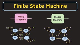
Finite State Machine Explained | Mealy Machine and Moore Machine | What is State Diagram ?
15:11
คุณอยากเรียนเวลาไหนทุกวันไปตลอดชีวิต? เลือกเลย!
00:17
总算是用上情侣手机壳了 #玩一种很新的东西 #手机壳 #情侣
00:10
มายคราฟ, แต่ ไลค์ = หัวใจ!
00:52
Mealy and Moore State Machines (Part 1)
Neso Academy
ติดตาม
2.8M
ดาวน์โหลด
โหลดลิงค์.....
มุมมอง 1 498 150
0
0
เพิ่มลงใน
เพลย์ลิสต์ของฉัน
ดูภายหลัง
แชร์
แชร์
ฝัง
ขนาดวิดีโอ:
1280 X 720
853 X 480
640 X 360
แสดงแผงควบคุมโปรแกรมเล่น
เล่นอัตโนมัติ
เล่นใหม่
เผยแพร่เมื่อ 2 ม.ค. 2025
ความคิดเห็น • 275
ต่อไป
เล่นอัตโนมัติ
4:21
Mealy and Moore State Machines (Part 2)
Neso Academy
มุมมอง 628K
10:34
Introduction to State Table, State Diagram & State Equation
Neso Academy
มุมมอง 1.7M
15:11
Finite State Machine Explained | Mealy Machine and Moore Machine | What is State Diagram ?
ALL ABOUT ELECTRONICS
มุมมอง 278K
00:17
คุณอยากเรียนเวลาไหนทุกวันไปตลอดชีวิต? เลือกเลย!
GennoRing
มุมมอง 161K
00:10
总算是用上情侣手机壳了 #玩一种很新的东西 #手机壳 #情侣
摩摩
มุมมอง 4.3M
00:52
มายคราฟ, แต่ ไลค์ = หัวใจ!
จิน
มุมมอง 296K
12:31
ไทยพลิกแซงสิงคโปร์ 2-4! อาเซียนยกเป็นแมตช์สุดมันส์!! เหงียนชมดูไทยเล่นสนุกจริง!
หมีเก็บบอล
มุมมอง 51K
19:18
0111 Sequence Detector-Using Mealy and Moore FSM
Easy Electronics
มุมมอง 262K
13:30
Analysis of Clocked Sequential Circuits (with D Flip Flop)
Neso Academy
มุมมอง 749K
11:05
Finite State Machine (Finite Automata)
Neso Academy
มุมมอง 2M
36:46
Иван Ургант - Про возвращение Вечернего Урганта, Ёлки и природоведение / Опять не Гальцев
Плюшки
มุมมอง 3.7M
12:26
Mealy vs. Moore Machines Overview
Bruce Boatner
มุมมอง 420K
9:51
Lec-20: Moore Machine in TOC with example | What is Moore Machine in Hindi
Gate Smashers
มุมมอง 1M
11:40
Introduction to Counters | Important
Neso Academy
มุมมอง 2.2M
19:06
Design Procedure for Clocked Sequential Circuits
Neso Academy
มุมมอง 1.1M
39:39
ใครคือฆาตกรตัวจริง ?! EP.11 (ver. คืนคริสมาสต์ สุดสยอง !!!
Sunflowava
มุมมอง 307K
00:51
ไก่วิเศษ #การ์ตูน #นิทาน #cartoon
วัยรุ่นผาฮอม
มุมมอง 17K
4:08:46
Live!🔴 สิงคโปร์ VS ทีมชาติไทย เชียร์สดฟุตบอลฟุตบอล ASEAN Mitsubishi Electric Cup™ 2024
Thairath Sport
มุมมอง 555K
00:20
人是不能做到吗?#火影忍者 #家人 #佐助
火影忍者一家
มุมมอง 20M
2:55:01
LIVE🔴 : Singapore vs Thailand | ASEAN Championship 2024 | 17.12.24
BG SPORTS
มุมมอง 2.5M
1:23:46
【หนังพากย์ไทย】ยอดฝีมือสังหารนักโทษ แต่นักโทษเป็นปรมาจารย์กังฟูที่ซ่อนอยู่ เขาจัดการทั้งหมดในทันที
Fresh Thailand
มุมมอง 468K
01:34
The White Lotus Season 3 | Official Teaser | Max
Max
มุมมอง 1.3M
00:18
ถ้าต้องทำ การบ้าน ตลอดชีวิต? คุณจะเลือกแบบไหน!
GennoRing
มุมมอง 468K