Thanks, Im subbed now! Was looking for a circuit to charge 1000mAh batteries for use on model train lights! Exactly what I need. Im using regular DC power for my train cars which varies in voltage and polarity. I suspect I could use a bridge rectifier and voltage regulator circuit in front of the tp module to limit voltage to the module to a maximum of 5vdc in the correct polarity. I recently was given about 200 of the batteries so I thought this would be good to keep constant lighting in the passenger cars of my HO train collection.
I believe that you can connect the MT3608 directly to the out+ and out- without needing an extra MOSFET and diode, have you tried that? It shouldn't negatively affect the lithium cell.
I have seen circuits where the Source and Drain connections are interchanged. Please clarify why the output from the TP4056 module is connected to the Drain and not the Source. Not sure if I am missing anything. Thanks.
There is a lot of confusion online about that, if you are still confused after watching the video you should make some tests yourself so that you can see what happens if you connect it the other way around. If you do you'll notice that the circuit doesn't behave corretly. As for how exactly I don't remember much because i did this a long time ago but i think the battery will go over the 4.2V volts while charging if you switch the connection of the mosfet or something like that
sure, that's a pull down resistor, it's there to discharge the mosfet gate when power is disconnected. Here a deeper explanation with examples : th-cam.com/video/Wd6NzCY3NgI/w-d-xo.html
Does there need to be a minimum current draw on the load, i notice my tp4056 doesn't have any voltage on the output unless i connect B- and out-. I have an esp32 connected to it and a neo gps module
This might not be necessary, and the module is actually working correctly. Apparently, in certain conditions, it is just charging so slowly close to the 4.2 end voltage range, that it seems like it would overcharge, but it will not, it will actually just take much longer to charge fully. The explanation is in this video th-cam.com/video/f2yMs-JAyQM/w-d-xo.html
Thanks for sharing this! To be honest I don't know enough to say if it is true or not without doing some testing. I remember testing this before and what happened in my case was that the module would signal that the battery was full but the charging voltage would slowly rise above 4.2 volts. It might have been the case that my module was faulty, it 's not too rare to have a couple of modules that don't work when you order them in bulk from china. it might be worth it to investigate this further. However personally I would suggest using the circuit in the video as well to add a layer of extra security/protection against faulty or failing components. Even if it's redundant, for a couple of extra bucks it's worth it especially if you are working with lithium batteries, as they can catch fire quite easily. This is of course my personal preference/opinion so feel free to ignore it.
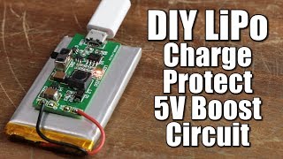
look at the circuit diagram in the video it shows how to connect the 5v booster. Remember to consider the difference in voltage between battery and power cable. the battery has a voltage of 3.7, if you adjust battery output to 5v using the booster, you will have an output voltage higher than 5v when the power cable is connected (probably around 6.3 v). if you want to keep a constant 5v in both cases consider using a voltage regulator with a capacitor instead, this video shows how a voltage regulator works and how to use it: th-cam.com/video/PnxyLaGTaAc/w-d-xo.html
that's a pull down resistor, it's there to discharge the mosfet gate when power is disconnected. Here a deeper explanation with examples : th-cam.com/video/Wd6NzCY3NgI/w-d-xo.html
If you are interested in the 3D design there is a link in the description of the stirrer to download them. I have never used Kicad, it's something I would love to learn to use but sadly I'm very busy at the moment so I don't have the time for it. Feel free to follow the diagram I showed in the stirrer tutorial to design your own, you can keep basically the same circuit and instead of the pwm and the motor you can connect whatever you want to the output of the MT3608, just make sure to regulate the voltage first. I hope this helps
May i ask something about the situation in which the usb is connected? Does the battery will be in charging mode at the same time? If it is , is it possible to connect such a 5V solar panel to the TP4056 module? And is it ok to conect the usb for a long time? will it damage the TP4056 ? I ve a problem how do the connection to esp32 will be ? does it need a voltage devider?
if the usb is connected and it's supplying 5v to the tp4056 then the battery is disconnected from the load, now if your load consumes less power than what the usb can provide then you both charge the battery and supply power to the load with the usb. I don't know about the panel as I never used one but a problem that i can see right away is that you won't have a constant 5v and the circuit might not work correctly on lower or higher voltages. I don't know if a low voltage can damage the tp4056 but a high enough voltage can for sure do some damage. to connect something to the circuit simply ignore the red module and the motor, regulate the output voltage of the voltage booster and then connect to it's output whatever you want to power up just be sure that the charging circuit and load are ok with the voltage fluctuation that you might have in your system so that you don't damage anything. for the divider is up to you. you can already regulate the output voltage using the MT3608 potentiometer but if you need to lower the voltage somewhere else you can use it
Thanks for the detailed explanation, it really helpful and i understand better. However, may i ask another question for instance, given the same circuit used with the additional of Esp32 as the MCU and i want to measure the voltage of the li-on battery using the voltage sensor module. How will the connection will be? can it work if i connect it from the Battery directly and connect it to Analog pin? what do u think? @engibored3207
@@fariszainuddin9842 you can do that if the analog pin can handle 5v but if you connect the sensor directly to the battery it will keep draining the battery and you will be bypassing the overdischarge protection of the tp4056, unless the battery has another protection circuit already integrated. If the battery is unprotected I would suggest connecting the sensor to the output of the tp4056, so that you read the ouput voltage of the module which should be around 4.2 V when the battery is at 3.7 v, and should decrease as the battery discharges. by doing a bit of math in the esp32 you should be able to figure out the voltage of the battery. If this doesn't work try looking for a battery monitoring circuit online you'll probably find something
If you follow the circuit showed in the video no but there might be a way to build a circuit that does the same with an N channel mosfet, try to google it maybe you'll find something
Is it possible to make an uninterruptible power supply in this way? In other words, when you cut the power, the motor will be fed from the battery, and when you give it power, it will be fed from the power.
@@engibored3207 Well, let's say the power went out, the load started to be fed from the battery, and it was fed at once until it reduced the voltage below 3V (tp4056 decharge cutoff threshold) + the load drew more than 100 milliamps of current (trickle current), then the power came back, will the tp4056 start charging again ? i mean, after a long power outage, will battery recover charging?
the charging module i used has a DW01 chip on it which is in charge to monitor the battery and it offers overcharge and overdischarge protection, this means that in the case the power is out the module will disconnect the battery once the battery's voltage reaches 2.4 v (I'm going by heart here check the datasheet to be sure), at this point your load is not powered anymore since the battery is disconnected and there is no power cable connected. When you connect the power cable the battery should start charging and the load should be powered once again. Now the charging module will reconnect the battery once the battery's voltage reaches 3v if i remember correctly (again check the datasheet to be sure), meaning that if you remove power and the battery has a voltage below 3v, your load won't have any power. If you do the same but the voltage of the battery is over 3v then your load will receive power from the battery until reaching 2.4v and the cycle will restart. For the current you should check your battery datasheet but if it allows to draw a current over 100 ma you should be fine since the tp4056 allows to draw 1A for sure. Now if you trigger the overcurrent protection you have to disconnect and reconnect the load to restart the module. I haven't test this but in theory connecting the power cable should disconnect the load from the tp4056 output so if you connect and disconnect the power cable the load should be disconnected and reconnected to the module, and the module should reconnect the battery when the cable is removed. The best thing you can do to see if it works is test it unfortunately or find a video of someone testing this. This video might explain the tp4056 module a bit better of how i did it here: th-cam.com/video/Lk__xTxLlY0/w-d-xo.html
@@engibored3207 the problem here is "disconnect and reconnect the load, to start cycle again", meaning (for me at least) no unnterrupted UPS.. if there is no power and the battery is dead + power is connected again , I don't think that the module will start charging again (or even if it charges the load will definitely not work) ,because in this case, it will give power directly to the load (unless we unplug the load, wait to battery voltage >3 and plug the load again)..
I'm not sure I'm understanding your problem correctly and maybe I explained it poorly but just to clarify a few points (at least as far as my understanding of this circuit goes, keep in mind I'm no expert and I can make mistakes): - you don't have to actually disconnect and reconnect the load to the charging module (or battery) manually when you trigger the overcurrent protection this is done automatically by the p mosfet when you connect and disconnect the power cable (at least in theory, sorry but I'm no expert and I haven't test this case) - if power cable is connected, the load is powered by the power cable regardless of the state of the battery (dead or alive) - if the power cable is connected, the battery is not used to power the load regardless of it's state. - The power cable is charging the battery and powering the load at the same time always when connected. this is true until the battery is full, when it is full the power cable still powers the load but it's not charging the battery anymore (keep in mind that the battery is disconnected from the load at this point but it will be reconnected automatically when the power cable is removed). -The charging module shouldn't allow the battery to die, so if the voltage of the battery reaches 2.4 v the module disconnects it but if you plug the cable at that point the cable will power the load and charge the battery at the same time. The load will stop working only if the power cable is disconnected and the battery voltage is below 3v (if the overdischarge protection has already kicked in) or until it reaches 2.4 volt if the protection has not been triggered. - when disconnecting the cable and switching to the battery to power the load there might be a short interrupt in the power to the load. This can be a problem in some applications. In theory you could fix this by connecting a capacitor in parallel before the booster (this will work as a short duration emergency battery that supplies power to the load while the circuit switches between cable and battery). this video probably explains the concept i'm referring to way better than me: th-cam.com/video/X4EUwTwZ110/w-d-xo.html - if the battery is actually dead and by that I mean it's gone and it's not able to hold the charge anymore than the only thing that can power the circuit is the power cable - what you described here: "if there is no power and the battery is dead + power is connected again , I don't think that the module will start charging again (or even if it charges the load will definitely not work) ,because in this case, it will give power directly to the load (unless we unplug the load, wait to battery voltage >3 and plug the load again)." should not be the case since: - when the power cable is connected the p mosfet disconnects the output of the charging module from the load automatically meaning that the battery is disconnected from the load (this happens always, doesn't matter if the battery is dead or alive). at this point with the battery disconnected from the load the power cable does 2 things: -it charges the battery (while the battery is disconnected from the load, and the disconnection is done automatically when you plug the cable) - it powers the load while charging the battery. what you described should happen only if: -the power supply (power cable) is undersized meaning that it's not powerful enough to charge the battery and load at the same time so changing the power supply should fix the problem - the battery is actually dead ( meaning it's not able to hold charge). in this situation if you connect the power cable it will still disconnect the battery from the load and try to load the battery, but the load will be powered by the cable for sure if the power supply is powerful enough to do so. I'm not sure I answered your question but I hope this helps.
that's a pull down resistor, it's there to discharge the mosfet gate when power is disconnected. Here a deeper explanation with examples : th-cam.com/video/Wd6NzCY3NgI/w-d-xo.html
@@engibored3207for my project iam gonna solder these components in a small PCB and I will be using a type c usb cable connected to typical smart phone charger . Iam trying to power my raspberry Pi Pico with this setup.additionally iam adding a buck at the end , between this circuit and raspberry Pi to ensure a stable voltage. It should work even if I power the TP4056 using usb cable right ... I've checked my smart phone charger it's rated 5V , 2A or 9V 2A , it shouldn't be causing any issue to the MOSFET I guess...
@@keralagamingbuddy8472 just remember to check the components datasheets to make sure that all the components can handle the supplied voltages/amperages and good luck!
Hello, sadly I don't have an lcd laying around at the moment. I'm not sure where or to what you want to add your lcd but if it is a raspberry this tutorial might help you out: th-cam.com/video/VczNDDkFiAI/w-d-xo.html


Newbie here learned something new! Current limiting diode :) Very useful.
Thanks, Im subbed now! Was looking for a circuit to charge 1000mAh batteries for use on model train lights! Exactly what I need. Im using regular DC power for my train cars which varies in voltage and polarity. I suspect I could use a bridge rectifier and voltage regulator circuit in front of the tp module to limit voltage to the module to a maximum of 5vdc in the correct polarity.
I recently was given about 200 of the batteries so I thought this would be good to keep constant lighting in the passenger cars of my HO train collection.
you're welcome I'm glad you found it useful
I believe that you can connect the MT3608 directly to the out+ and out- without needing an extra MOSFET and diode, have you tried that? It shouldn't negatively affect the lithium cell.
if you do that you have to disconnect the load from the battery before charging it otherwise you risk damaging the battery
I have seen circuits where the Source and Drain connections are interchanged. Please clarify why the output from the TP4056 module is connected to the Drain and not the Source. Not sure if I am missing anything. Thanks.
There is a lot of confusion online about that, if you are still confused after watching the video you should make some tests yourself so that you can see what happens if you connect it the other way around. If you do you'll notice that the circuit doesn't behave corretly. As for how exactly I don't remember much because i did this a long time ago but i think the battery will go over the 4.2V volts while charging if you switch the connection of the mosfet or something like that
Thank you for the video, but what is the role of the 1K resistor?
sure, that's a pull down resistor, it's there to discharge the mosfet gate when power is disconnected. Here a deeper explanation with examples : th-cam.com/video/Wd6NzCY3NgI/w-d-xo.html
Does there need to be a minimum current draw on the load, i notice my tp4056 doesn't have any voltage on the output unless i connect B- and out-.
I have an esp32 connected to it and a neo gps module
I don't think there is a minimum current draw for the load but I never tested it to see if there is one. maybe the tp4056 is a faulty one I don't know
Thank you for this usful video 👍👍👍
you re welcome I'm glad you found it useful
This might not be necessary, and the module is actually working correctly. Apparently, in certain conditions, it is just charging so slowly close to the 4.2 end voltage range, that it seems like it would overcharge, but it will not, it will actually just take much longer to charge fully. The explanation is in this video th-cam.com/video/f2yMs-JAyQM/w-d-xo.html
Thanks for sharing this! To be honest I don't know enough to say if it is true or not without doing some testing. I remember testing this before and what happened in my case was that the module would signal that the battery was full but the charging voltage would slowly rise above 4.2 volts. It might have been the case that my module was faulty, it 's not too rare to have a couple of modules that don't work when you order them in bulk from china. it might be worth it to investigate this further. However personally I would suggest using the circuit in the video as well to add a layer of extra security/protection against faulty or failing components. Even if it's redundant, for a couple of extra bucks it's worth it especially if you are working with lithium batteries, as they can catch fire quite easily. This is of course my personal preference/opinion so feel free to ignore it.
If we want to connect a 5v booster to the battery output, how should we make the connection?
look at the circuit diagram in the video it shows how to connect the 5v booster. Remember to consider the difference in voltage between battery and power cable. the battery has a voltage of 3.7, if you adjust battery output to 5v using the booster, you will have an output voltage higher than 5v when the power cable is connected (probably around 6.3 v). if you want to keep a constant 5v in both cases consider using a voltage regulator with a capacitor instead, this video shows how a voltage regulator works and how to use it: th-cam.com/video/PnxyLaGTaAc/w-d-xo.html
Why do you need a 10k resistor connecting from 5v + to negative load?
that's a pull down resistor, it's there to discharge the mosfet gate when power is disconnected. Here a deeper explanation with examples : th-cam.com/video/Wd6NzCY3NgI/w-d-xo.html
You made my day man...🤩
thanks man I'm glad to hear that
Can you make a 3D printer design tutorial from a magnetic stirrer and design the PCB in Kicad
If you are interested in the 3D design there is a link in the description of the stirrer to download them. I have never used Kicad, it's something I would love to learn to use but sadly I'm very busy at the moment so I don't have the time for it. Feel free to follow the diagram I showed in the stirrer tutorial to design your own, you can keep basically the same circuit and instead of the pwm and the motor you can connect whatever you want to the output of the MT3608, just make sure to regulate the voltage first. I hope this helps
May i ask something about the situation in which the usb is connected? Does the battery will be in charging mode at the same time? If it is , is it possible to connect such a 5V solar panel to the TP4056 module? And is it ok to conect the usb for a long time? will it damage the TP4056 ? I ve a problem how do the connection to esp32 will be ? does it need a voltage devider?
if the usb is connected and it's supplying 5v to the tp4056 then the battery is disconnected from the load, now if your load consumes less power than what the usb can provide then you both charge the battery and supply power to the load with the usb.
I don't know about the panel as I never used one but a problem that i can see right away is that you won't have a constant 5v and the circuit might not work correctly on lower or higher voltages. I don't know if a low voltage can damage the tp4056 but a high enough voltage can for sure do some damage.
to connect something to the circuit simply ignore the red module and the motor, regulate the output voltage of the voltage booster and then connect to it's output whatever you want to power up just be sure that the charging circuit and load are ok with the voltage fluctuation that you might have in your system so that you don't damage anything.
for the divider is up to you. you can already regulate the output voltage using the MT3608 potentiometer but if you need to lower the voltage somewhere else you can use it
Thanks for the detailed explanation, it really helpful and i understand better. However, may i ask another question for instance, given the same circuit used with the additional of Esp32 as the MCU and i want to measure the voltage of the li-on battery using the voltage sensor module. How will the connection will be? can it work if i connect it from the Battery directly and connect it to Analog pin? what do u think? @engibored3207
@@fariszainuddin9842 you can do that if the analog pin can handle 5v but if you connect the sensor directly to the battery it will keep draining the battery and you will be bypassing the overdischarge protection of the tp4056, unless the battery has another protection circuit already integrated. If the battery is unprotected I would suggest connecting the sensor to the output of the tp4056, so that you read the ouput voltage of the module which should be around 4.2 V when the battery is at 3.7 v, and should decrease as the battery discharges. by doing a bit of math in the esp32 you should be able to figure out the voltage of the battery. If this doesn't work try looking for a battery monitoring circuit online you'll probably find something
Thank you very much for the insightful explanation. It really helpful. @engibored3207
No problem I'm glad you found it useful @@fariszainuddin9842
Which MOSFET do you recommend to use here?
there is the part list in the description if you need it
Is it possible to use a N Channel mosfet?
If you follow the circuit showed in the video no but there might be a way to build a circuit that does the same with an N channel mosfet, try to google it maybe you'll find something
Is it possible to make an uninterruptible power supply in this way? In other words, when you cut the power, the motor will be fed from the battery, and when you give it power, it will be fed from the power.
yes this is what this circuit does, additionally it also charges the battery when power is connected
@@engibored3207 Well, let's say the power went out, the load started to be fed from the battery, and it was fed at once until it reduced the voltage below 3V (tp4056 decharge cutoff threshold) + the load drew more than 100 milliamps of current (trickle current), then the power came back, will the tp4056 start charging again ? i mean, after a long power outage, will battery recover charging?
the charging module i used has a DW01 chip on it which is in charge to monitor the battery and it offers overcharge and overdischarge protection, this means that in the case the power is out the module will disconnect the battery once the battery's voltage reaches 2.4 v (I'm going by heart here check the datasheet to be sure), at this point your load is not powered anymore since the battery is disconnected and there is no power cable connected. When you connect the power cable the battery should start charging and the load should be powered once again. Now the charging module will reconnect the battery once the battery's voltage reaches 3v if i remember correctly (again check the datasheet to be sure), meaning that if you remove power and the battery has a voltage below 3v, your load won't have any power. If you do the same but the voltage of the battery is over 3v then your load will receive power from the battery until reaching 2.4v and the cycle will restart. For the current you should check your battery datasheet but if it allows to draw a current over 100 ma you should be fine since the tp4056 allows to draw 1A for sure. Now if you trigger the overcurrent protection you have to disconnect and reconnect the load to restart the module. I haven't test this but in theory connecting the power cable should disconnect the load from the tp4056 output so if you connect and disconnect the power cable the load should be disconnected and reconnected to the module, and the module should reconnect the battery when the cable is removed. The best thing you can do to see if it works is test it unfortunately or find a video of someone testing this. This video might explain the tp4056 module a bit better of how i did it here: th-cam.com/video/Lk__xTxLlY0/w-d-xo.html
@@engibored3207 the problem here is "disconnect and reconnect the load, to start cycle again", meaning (for me at least) no unnterrupted UPS..
if there is no power and the battery is dead + power is connected again , I don't think that the module will start charging again (or even if it charges the load will definitely not work) ,because in this case, it will give power directly to the load (unless we unplug the load, wait to battery voltage >3 and plug the load again)..
I'm not sure I'm understanding your problem correctly and maybe I explained it poorly but just to clarify a few points (at least as far as my understanding of this circuit goes, keep in mind I'm no expert and I can make mistakes):
- you don't have to actually disconnect and reconnect the load to the charging module (or battery) manually when you trigger the overcurrent protection this is done automatically by the p mosfet when you connect and disconnect the power cable (at least in theory, sorry but I'm no expert and I haven't test this case)
- if power cable is connected, the load is powered by the power cable regardless of the state of the battery (dead or alive)
- if the power cable is connected, the battery is not used to power the load regardless of it's state.
- The power cable is charging the battery and powering the load at the same time always when connected. this is true until the battery is full, when it is full the power cable still powers the load but it's not charging the battery anymore (keep in mind that the battery is disconnected from the load at this point but it will be reconnected automatically when the power cable is removed).
-The charging module shouldn't allow the battery to die, so if the voltage of the battery reaches 2.4 v the module disconnects it but if you plug the cable at that point the cable will power the load and charge the battery at the same time. The load will stop working only if the power cable is disconnected and the battery voltage is below 3v (if the overdischarge protection has already kicked in) or until it reaches 2.4 volt if the protection has not been triggered.
- when disconnecting the cable and switching to the battery to power the load there might be a short interrupt in the power to the load. This can be a problem in some applications. In theory you could fix this by connecting a capacitor in parallel before the booster (this will work as a short duration emergency battery that supplies power to the load while the circuit switches between cable and battery). this video probably explains the concept i'm referring to way better than me: th-cam.com/video/X4EUwTwZ110/w-d-xo.html
- if the battery is actually dead and by that I mean it's gone and it's not able to hold the charge anymore than the only thing that can power the circuit is the power cable
- what you described here: "if there is no power and the battery is dead + power is connected again , I don't think that the module will start charging again (or even if it charges the load will definitely not work) ,because in this case, it will give power directly to the load (unless we unplug the load, wait to battery voltage >3 and plug the load again)."
should not be the case since:
- when the power cable is connected the p mosfet disconnects the output of the charging module from the load automatically meaning that the battery is disconnected from the load (this happens always, doesn't matter if the battery is dead or alive). at this point with the battery disconnected from the load the power cable does 2 things:
-it charges the battery (while the battery is disconnected from the load, and the disconnection is done automatically when you plug the cable)
- it powers the load while charging the battery.
what you described should happen only if:
-the power supply (power cable) is undersized meaning that it's not powerful enough to charge the battery and load at the same time so changing the power supply should fix the problem
- the battery is actually dead ( meaning it's not able to hold charge). in this situation if you connect the power cable it will still disconnect the battery from the load and try to load the battery, but the load will be powered by the cable for sure if the power supply is powerful enough to do so.
I'm not sure I answered your question but I hope this helps.
Could you not just use another schottky diode instead of the mosfet?
You can do that too if you only have those
bro can you tell me the purpose of the 10k resistor ?
that's a pull down resistor, it's there to discharge the mosfet gate when power is disconnected. Here a deeper explanation with examples : th-cam.com/video/Wd6NzCY3NgI/w-d-xo.html
@@engibored3207 thank you bro , good explanation ❣️
@@engibored3207for my project iam gonna solder these components in a small PCB and I will be using a type c usb cable connected to typical smart phone charger . Iam trying to power my raspberry Pi Pico with this setup.additionally iam adding a buck at the end , between this circuit and raspberry Pi to ensure a stable voltage. It should work even if I power the TP4056 using usb cable right ... I've checked my smart phone charger it's rated 5V , 2A or 9V 2A , it shouldn't be causing any issue to the MOSFET I guess...
@@keralagamingbuddy8472 just remember to check the components datasheets to make sure that all the components can handle the supplied voltages/amperages and good luck!
@@engibored3207 ❣️
Hello,Can you add an LCD component? I need the tutorial
Hello, sadly I don't have an lcd laying around at the moment. I'm not sure where or to what you want to add your lcd but if it is a raspberry this tutorial might help you out: th-cam.com/video/VczNDDkFiAI/w-d-xo.html