Just recently got interested in RF circuitry, thank you so much for sharing your experience and knowledge! You're the type of people that make the internet go round! :)
These videos of yours Alan, are fantastic, really explain the workings of our "toys", hope to see more and I hope teachers use your videos to help their students understand these concepts, visualization helps greatly.
Awesome info as always! Great to see you churning out invaluable videos again after a noteworthy hiatus (happy, happy). Welcome back & hope you're feeling better!
Definately a "keeper". I frequently refer to your videos when designing something. Great resource and a good refresher for topics that I haven't worked with recently. I'm working on a design for a LNA and antenna switcher that will be mast mounted. I have an idea to provide power via a bias tee as well as a low speed digital signal for the switching logic. It will be receive only so I don't have to worry about high power RF.
I also used bias T devices to combine RF and DC current to flow through EMI low-pass filters to test their frequency response in relation to load current.
Thanks for the excellent video Alan! Of course now I will have to go spend some money at Mini Circuits and do some of my own experiments! Excellent explanation of the subject, as always. 73, W3AL, Alan
My new Beko amplifier can apply DC to a remote-mounted preamp via the RF cable. However, the 2M beam is a dead short to DC and this precluded using the internal bias tee in the amplifier. That bias tee in the preamp must be pretty well designed since it should work to 2.5kW RF power. Great video again, thanks! 73 de KT1R Lou in Maine
This is such an awesome explanation. I was going to build my own Bias Tee for HF - powering a remote antenna tuner, and this was an awesome explanation!
I recently got some cheapie Bias-T's from eBay to just to have at the bench. I noticed that with the RF input port unterminated that the supply voltage appears at that port for a brief instant when powering up the T (just measuring with a DMM). A "quality" Bias-T that I tried the same thing on doesn't demonstrate that anomaly. Think it's probably the coupling cap charging for an instant then discharging thru the meter. If you terminate the port with 50 ohms it doesn't appear at all. Having said that I'd be a bit concerned that a device might be sensitive to that "spike". Need to do some more experimenting but had never seen that effect before. TNX for another great video Alan! 73 - Dino KL0S
Hmm, I wonder if it would be possible to power a stepper motor to tune the vacuum variable cap of my mag loop with a bias tee. Then maybe use like an ESP32 or something to send it commands wirelessly for end stop sensing and what have you. Otherwise, currently, I'm just using unshielded Cat5e as power and end stop sense. Lots of RF hash when the motor is spinning, so, anytime I change frequencies... Probably doesn't help that I ran the Cat5e next to the coax of the antenna and didn't use any chokes. Free wire is free wire though. Very quiet noise floor when I'm on a freq. I think I will research these Bias Tee thingers some more, thank you for the video.
why aren't you doing more videos ? I really enjoy all of them, perfectly done. the repair ones are also awesome I love to see the troubleshooting process. thank you
It really comes down to time. What a lot of people don't realize is that each minute of produced video represents 20-30 minutes or more of total time commitment. This involves all of the planning of what to present, how to present it, what documentation/notes to prepare, what experiments to run, setup/test/refine experiments, finalize notes, etc. - all of this is before the actual shooting, editing and rendering a final video. Full time job, family commitments and even other hobbies all compete for my time. I wish I could do more.
No worries! A lot of folks don't realize how much time it takes to make quality videos - unfortunately it is not simply sitting down at the bench and shooting... I wish it was that easy.
Hi Alan, fantastic informative video as always but would it be possible to have the mathematics around component selection and some practical demonstrations of component selection please? I’m particularly interested in powering a remote antenna switch. I had thought about separate DC offsets to switch 4 channels but found a great way to use WiFi and then co from the antenna switching remotely. I would really enjoy an in-depth video of component selection and SLCC and ATC over MLCC, silver mica. The core and saturation of the inductors etc. I’ve already had good success but still learning a great deal. 73
Thank you this was a great video. I have a question I am designing a Bias Tee for a school project but it needs to be a kelvin bias tee. To add the sense port do I replicate the DC port section of the bias tee with the same number of inductors and values?
Hmm, interesting. I never saw a kelvin bias tee. I would imagine you could replicate the DC path. However, you could use lossier inductors (ferrite based) since you don't have to worry about saturation...
Yes it is. This is the first project I've used it for. First impression is that it's pricey for what it does. But, it is really nice to work with for creating and editing the notes pages - probably saved me going through at least 15-20 sheets of paper. It creates PDF very easily, but they are on the large size (file size). Some editing features are missing (like being able to delete a page from a notebook, that's why there's an extra page in the PDF notes). Very nice pencil & paper feel. I'd like it if there was some storage mechanism for the stylus.
Hi Alan, I m designing a bias T for 10 MHz, L band(950-2150 MHz) and DC. What I understood is inductors which will pass DC must block 10 MHz and L band.My current required is 2 Amp.Can u suggest what parameters I should consider while selecting inductors??
Tricky - you'll need to ensure that the inductor is low enough in value such that is it still below its self-resonant frequency at 2.150GHz, still have enough reactance to be effective at 10MHz, and not saturate with 2A of current. Sounds like a difficult set of tradeoffs possibly, depending upon how much inductive reactance you need to meet your RF performance requirements.
@@w2aew Thanks for the reply...Have learnt a lot from your videos....Your content n presenting style is excellent.... actually I m planning to use two series inductors (got this from web),1 for blocking 10 MHz and another for L band RF.... Isolation required is around 60-65 dB and insertion less than 1 dB
Your Bias Tee video was excellent. However there is one thing that you did not comment on and that was the surge voltage that appears on the RF output when power to the bias tee is turned on and off. I have experienced this when used with DSO's where the spike can be as much as 2 volts both negative and positive which pops the input stage to the DSO. Do you have any thoughts on this?
Would I be right in my (low-effort) assumption that 1) the adjustable antenna has a bias tee inside as well, and 2) the DC output of that bias tee is used to drive the motor?
thanks Alan. Great video as always. Would you consider doing a video on RF circulators and their use in duplexers and reflection amplifiers? I haven't seen that topic listed in the index of your videos. Regards, VE7NEU
Thank you for a great presentation. A side question on Bias-Tees, is there a preferred location to insert a Bias Tee, i.e. as close as possible to the Rx/Tx, closer to the antenna or it doesn't really matter? Thank you.
Excellent video! Would it be possible to power a small cctv camera that outputs a PAL/NTSC signal using this approach? Shall another bias tee be used at the camera to separate the dc component?
The good thing is that the upper frequency of NTSC/PAL isn't very high, so a large RF Choke or inductor shouldn't impose a problem. The bigger issue may be some artifacts in the video due to AC coupling.
Could i use 2pcs of bias tee box, to use a with a non bias tee SDR radio and a non bias tee LNA? I mean where i use the second one to take out power (reversed) and feed the LNA with that. I has some few SDR radios, among them the RTL-SDR blog V3 that has bias tee inbuilt via software switch. Could i use 1pcs bias tee the same way with having it at the non bias tee LNA to feed it where the RTL-SDR blog V3 gives the power out to the second bias tee that feeds the LNA? I guess these will work like that with both input and output use, or perhaps not?
If the DC bias was pulsed or even AC, would the DC decoupling capacitor on the RF input still work? It would be interesting to look at the "DC" bias under some unusual conditions. I wonder how far this can go. Maybe two "DC" bias inputs with different characteristics at different locations for example. One "bias" triggering another. Starting to look like a complicated communication bus.
Yes, it is all possible. If the frequency of the pulsed or varying DC is well below the cutoff of the RF coupling capacitor, it will largely get get blocked.
For that wide of a frequency range, you might be better off with a commercially made device because some kind of multi inductor arrangement will likely be needed.
I already have a few videos that might be useful for you: Diodes as switches: th-cam.com/video/YBNIq_d56sA/w-d-xo.html Basics of PIN diodes: th-cam.com/video/XpYsCM_Wf50/w-d-xo.html PIN diode based T/R switch: th-cam.com/video/A1BAq0KxIdc/w-d-xo.html
hey this is very helpful thank you --- I am trying to configure a mini whip antenna that I picked up on amazon. It came with a bias tee to power the antenna. I have 'RF out' on the antenna PCB into 'RF + DC' on the T, and 'RF' of the T into scope. I've powered the T across the acceptable range. I am getting basically no noise, very clean flat DC signal, strong, but no RF whatsoever showing up on scope. I tried reversing the config as well, same deal can you please help? keep in mind I am a noob. this is the unit, cannot find documentation for it www.amazon.ca/Mini-Whip-Shortwave-Active-Antenna-Interface/dp/B0828FD9GN
Shortwave signals picked up on a tiny active antenna like that will be VERY low amplitude, likely too low to measure with an oscilloscope. You'd have to test it with a shortwave receiver or spectrum analyzer.
And that's why they call it "black magic" , you have to be a wizard to understand the rf stuff where capactors become inductors and inductors become capacitors.
I first thought you had developed some kind of tremor, because the drawings and characters were all a little bit jagged. Which means it took me some time to get that it was not paper you had drawn on.


Just recently got interested in RF circuitry, thank you so much for sharing your experience and knowledge! You're the type of people that make the internet go round! :)
Thirteen minute worth watching your video than any class. Thanks Alan for show and tell.
These videos of yours Alan, are fantastic, really explain the workings of our "toys", hope to see more and I hope teachers use your videos to help their students understand these concepts, visualization helps greatly.
Awesome info as always! Great to see you churning out invaluable videos again after a noteworthy hiatus (happy, happy). Welcome back & hope you're feeling better!
Great job. You can tell that a lot of work goes into making these videos. Very much appreciated - Thanks
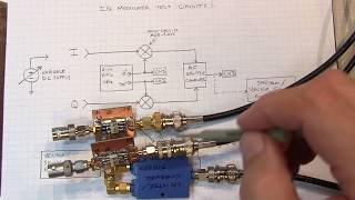
I liked the Mini Circuit teardowns, didn't expect the multiple inductors in series.
Thank you for this great video. You are getting better at teaching with every video!
I am immensely glad that the great Alan released a new one.
Definately a "keeper". I frequently refer to your videos when designing something. Great resource and a good refresher for topics that I haven't worked with recently. I'm working on a design for a LNA and antenna switcher that will be mast mounted. I have an idea to provide power via a bias tee as well as a low speed digital signal for the switching logic. It will be receive only so I don't have to worry about high power RF.
I also used bias T devices to combine RF and DC current to flow through EMI low-pass filters to test their frequency response in relation to load current.
Excellent video! You do a great job demystifying things and I really enjoy the practical examples!
I am amazed. I wish I can be as knowledgeable both theoretically/practically as you are..
Thanks again
There is a lot of study and work put behind each of these videos. All it takes is research, study and experimentation - and practice!
I am a simple man. I see Alan video about RF, I insta watch!
Thanks for the excellent video Alan! Of course now I will have to go spend some money at Mini Circuits and do some of my own experiments! Excellent explanation of the subject, as always.
73, W3AL, Alan
My new Beko amplifier can apply DC to a remote-mounted preamp via the RF cable. However, the 2M beam is a dead short to DC and this precluded using the internal bias tee in the amplifier. That bias tee in the preamp must be pretty well designed since it should work to 2.5kW RF power. Great video again, thanks! 73 de KT1R Lou in Maine
Not sure how many times I've watched this, but I can only give 1 thumbs up, sorry! :)
Please more rf stuff. I install cable and find it super interesting. Thanks for the content!
This was a very interesting video, I'm getting more and more interested in RF now, it's not too early to become a ham!
Hello Alan, explanations, the tablet and the teacher are "Remarkable"!!! ;)
This is such an awesome explanation. I was going to build my own Bias Tee for HF - powering a remote antenna tuner, and this was an awesome explanation!
Thank you for making such a good video!
Understand a bit more? More like a *LOT* more! Thank you Alan!!! =)
New to Radio.... thank you so much you've given me some great ideas.
Thank you again for great video
Great video as always, Alan.
Easy to unterstand. Good videos you make, thank you.
I actually really needed this, thanks a lot!
Thanks for this new video! Always great content!
Hi Alan,
Excellent visuals. Good to see another video. 73 WB3BJU
Nice video, Alan. Thanks. I need more equipment...
Excellent tutorial.Thanks.
I recently got some cheapie Bias-T's from eBay to just to have at the bench. I noticed that with the RF input port unterminated that the supply voltage appears at that port for a brief instant when powering up the T (just measuring with a DMM). A "quality" Bias-T that I tried the same thing on doesn't demonstrate that anomaly. Think it's probably the coupling cap charging for an instant then discharging thru the meter. If you terminate the port with 50 ohms it doesn't appear at all. Having said that I'd be a bit concerned that a device might be sensitive to that "spike". Need to do some more experimenting but had never seen that effect before. TNX for another great video Alan! 73 - Dino KL0S
Great explanation, thanks for the video!
Hmm, I wonder if it would be possible to power a stepper motor to tune the vacuum variable cap of my mag loop with a bias tee. Then maybe use like an ESP32 or something to send it commands wirelessly for end stop sensing and what have you. Otherwise, currently, I'm just using unshielded Cat5e as power and end stop sense. Lots of RF hash when the motor is spinning, so, anytime I change frequencies... Probably doesn't help that I ran the Cat5e next to the coax of the antenna and didn't use any chokes. Free wire is free wire though. Very quiet noise floor when I'm on a freq. I think I will research these Bias Tee thingers some more, thank you for the video.
Thanks again. Hope to DX you at some time in the future..
Another awesome video Alan...!! :)
Great video! Thank you.
As always your videos are excellent, complete, clear, you are an excellent teacher. Thank you for your time spent educating us. LU6FSD
Thank you sir. Very well done.
I can't believe I only find this video today, have been working on microwave for years......thanks for the illustration
I still have a working ATAS 100. I've always wondered how that worked. Very well explained as always. 73 NE5U Mike
8V applied will drive the antenna in one direction, 12V applied will drive it in the other direction.
That's interesting. 1-5V plus a 7V bias?
Schematic of controller is here:
k0lee.com/atasdir/ATAS-120TechnicalSupplement.pdf
Nice video ! If you turn the ZFBT-4R2GW+, there are some additional inductors on the bottom side :-)
why aren't you doing more videos ? I really enjoy all of them, perfectly done. the repair ones are also awesome I love to see the troubleshooting process. thank you
It really comes down to time. What a lot of people don't realize is that each minute of produced video represents 20-30 minutes or more of total time commitment. This involves all of the planning of what to present, how to present it, what documentation/notes to prepare, what experiments to run, setup/test/refine experiments, finalize notes, etc. - all of this is before the actual shooting, editing and rendering a final video. Full time job, family commitments and even other hobbies all compete for my time. I wish I could do more.
:D oh ok sorry, hopefully your channel will grow even more, and you'll be able give it more time, thank you again.
No worries! A lot of folks don't realize how much time it takes to make quality videos - unfortunately it is not simply sitting down at the bench and shooting... I wish it was that easy.
Nice video. I have really leaned a lot. Keep up the good work ^_^
I have a bias tee for an active loop antenna that I have. I also have a LNA. Can I use both together?
Likely yes, but set it up like: receiver > LNA > bias tee > active loop antenna.
@@w2aew Thanks for the response. I think I may try this tomorrow. I'm a little nervous I might damage something.
Nicely Explained, thank you.
Thanks a lot Sir.
Hi Alan, fantastic informative video as always but would it be possible to have the mathematics around component selection and some practical demonstrations of component selection please? I’m particularly interested in powering a remote antenna switch. I had thought about separate DC offsets to switch 4 channels but found a great way to use WiFi and then co from the antenna switching remotely. I would really enjoy an in-depth video of component selection and SLCC and ATC over MLCC, silver mica. The core and saturation of the inductors etc. I’ve already had good success but still learning a great deal. 73
What is that e-paper note pad were you using in the video (8:49) ? It is a very handy tool. Thanks!
www.remarkable.com
Thanks for teaching! :)
Thank you this was a great video. I have a question I am designing a Bias Tee for a school project but it needs to be a kelvin bias tee. To add the sense port do I replicate the DC port section of the bias tee with the same number of inductors and values?
Hmm, interesting. I never saw a kelvin bias tee. I would imagine you could replicate the DC path. However, you could use lossier inductors (ferrite based) since you don't have to worry about saturation...
@@w2aew Awesome thanks for the answer :)
Another GREAT video, Alan. Curious - is that a Remarkable tablet? I have been wondering about them and would love to hear what you think.
Yes it is. This is the first project I've used it for. First impression is that it's pricey for what it does. But, it is really nice to work with for creating and editing the notes pages - probably saved me going through at least 15-20 sheets of paper. It creates PDF very easily, but they are on the large size (file size). Some editing features are missing (like being able to delete a page from a notebook, that's why there's an extra page in the PDF notes). Very nice pencil & paper feel. I'd like it if there was some storage mechanism for the stylus.
Great as usually! Thx.
How well does a bias tee filter out the inherent dc noise from a typical cheap switching power supply wall wart?
It will likely help somewhat due to the RF blocking nature of the DC path.
Hi Alan, I m designing a bias T for 10 MHz, L band(950-2150 MHz) and DC. What I understood is inductors which will pass DC must block 10 MHz and L band.My current required is 2 Amp.Can u suggest what parameters I should consider while selecting inductors??
Tricky - you'll need to ensure that the inductor is low enough in value such that is it still below its self-resonant frequency at 2.150GHz, still have enough reactance to be effective at 10MHz, and not saturate with 2A of current. Sounds like a difficult set of tradeoffs possibly, depending upon how much inductive reactance you need to meet your RF performance requirements.
@@w2aew Thanks for the reply...Have learnt a lot from your videos....Your content n presenting style is excellent....
actually I m planning to use two series inductors (got this from web),1 for blocking 10 MHz and another for L band RF.... Isolation required is around 60-65 dB and insertion less than 1 dB
Your Bias Tee video was excellent. However there is one thing that you did not comment on and that was the surge voltage that appears on the RF output when power to the bias tee is turned on and off. I have experienced this when used with DSO's where the spike can be as much as 2 volts both negative and positive which pops the input stage to the DSO. Do you have any thoughts on this?
Sir any video on RF transmitter receiver module circuit diagram explaining the working of the circuit diagram
It would be nice if you have also covered how to calculate parameters of the capacitance and inductance for the given frequency and power.
what is the writing pad you are using?
Would I be right in my (low-effort) assumption that 1) the adjustable antenna has a bias tee inside as well, and 2) the DC output of that bias tee is used to drive the motor?
thanks Alan. Great video as always. Would you consider doing a video on RF circulators and their use in duplexers and reflection amplifiers? I haven't seen that topic listed in the index of your videos.
Regards,
VE7NEU
I'll have to add this to my long list (and I'll have to pick up some circulators too!).
Thank you.
Great sir.
Thank you for a great presentation. A side question on Bias-Tees, is there a preferred location to insert a Bias Tee, i.e. as close as possible to the Rx/Tx, closer to the antenna or it doesn't really matter? Thank you.
Doesn't really matter, it depends more on where it is easiest to run the power.
@@w2aew Awesome, thanks for that. That makes it a lot easier.
Useful video
Seems like basically the same as phantom power, I wonder why it's not called that
Excellent video! Would it be possible to power a small cctv camera that outputs a PAL/NTSC signal using this approach? Shall another bias tee be used at the camera to separate the dc component?
Yes, and yes.
w2aew Thank you!
NTSC/PAL is going to be tricky because the bandwidth extends pretty low, to the point where inductors start becoming quite big.
The good thing is that the upper frequency of NTSC/PAL isn't very high, so a large RF Choke or inductor shouldn't impose a problem. The bigger issue may be some artifacts in the video due to AC coupling.
Thank you all for your feedback!
Bias-Tee = DC injector. Maybe RF + DC diplexer 🙂
Could i use 2pcs of bias tee box, to use a with a non bias tee SDR radio and a non bias tee LNA?
I mean where i use the second one to take out power (reversed) and feed the LNA with that.
I has some few SDR radios, among them the RTL-SDR blog V3 that has bias tee inbuilt via software switch. Could i use 1pcs bias tee the same way with having it at the non bias tee LNA to feed it where the RTL-SDR blog V3 gives the power out to the second bias tee that feeds the LNA?
I guess these will work like that with both input and output use, or perhaps not?
Yes, you can use two Bias Tees like that - no problem.
I wish I could do more thumbs up on your videos. Amazing, Amazing. ...
If the DC bias was pulsed or even AC, would the DC decoupling capacitor on the RF input still work? It would be interesting to look at the "DC" bias under some unusual conditions. I wonder how far this can go. Maybe two "DC" bias inputs with different characteristics at different locations for example. One "bias" triggering another. Starting to look like a complicated communication bus.
Yes, it is all possible. If the frequency of the pulsed or varying DC is well below the cutoff of the RF coupling capacitor, it will largely get get blocked.
What should be the C and L values for 10Mhz-6000Mhz for a max 50V design
For that wide of a frequency range, you might be better off with a commercially made device because some kind of multi inductor arrangement will likely be needed.
I got confused by the DC port of the ZX86-12G-S+ one😵😵
Do you have any videos about waveguides or can you do a video on basic how waveguide works? Thanks.
I don't have any videos on waveguides, sorry about that. I'll add this to my big list...
awesome
I am giving power to my LNA of 12 volt but it not getting power power up it is generally stopping at 9.3-9.4 volt how to fix this
I am using ZX60-83LN12+ LNA
thank you !
Nice 👍 😊
TNX 4 another great video !
73 N8AUM
Please, explane about pin diodes as switches and variable attenuator
I already have a few videos that might be useful for you:
Diodes as switches: th-cam.com/video/YBNIq_d56sA/w-d-xo.html
Basics of PIN diodes: th-cam.com/video/XpYsCM_Wf50/w-d-xo.html
PIN diode based T/R switch: th-cam.com/video/A1BAq0KxIdc/w-d-xo.html
My H.F. Tee out to the antenna does not like to see D.C. low imp. ground, Well I just got the proper magnet wire and rewound the choak, W4GSM
Maybe you need another bias tee at the antenna to isolate the DC ground.
HI, I really need to watch what I am doing, Dave
thumbs up!...
hey this is very helpful thank you --- I am trying to configure a mini whip antenna that I picked up on amazon. It came with a bias tee to power the antenna. I have 'RF out' on the antenna PCB into 'RF + DC' on the T, and 'RF' of the T into scope. I've powered the T across the acceptable range. I am getting basically no noise, very clean flat DC signal, strong, but no RF whatsoever showing up on scope. I tried reversing the config as well, same deal
can you please help? keep in mind I am a noob. this is the unit, cannot find documentation for it www.amazon.ca/Mini-Whip-Shortwave-Active-Antenna-Interface/dp/B0828FD9GN
Shortwave signals picked up on a tiny active antenna like that will be VERY low amplitude, likely too low to measure with an oscilloscope. You'd have to test it with a shortwave receiver or spectrum analyzer.
I so so want that scope but i can't afford one.
Yes, I understand. I am very fortunate to be working for Tektronix and have access to this great equipment.
And that's why they call it "black magic" , you have to be a wizard to understand the rf stuff where capactors become inductors and inductors become capacitors.
You're writing on a tablet now! 😱
First time trying it out - so far, so good. A few little quirks, but overall I like it.
What type of tablet is that?
remarkable.com
I first thought you had developed some kind of tremor, because the drawings and characters were all a little bit jagged. Which means it took me some time to get that it was not paper you had drawn on.
Great video, thanks.
Very good tutorial. Thank you.