How to design NPN BJT based Overvoltage protection? Overvoltage protection using NPN BJT.

ฝัง
- เผยแพร่เมื่อ 22 พ.ค. 2024
- #foolishengineer #Transistor #Overvoltage
0:00 Skip Intro
00:24 What is over voltage protection
01:42 NPN transistor for OV protection
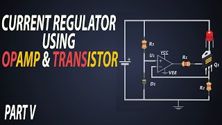
01:55 Circuit construction and working
03:55 Simulation 1
05:03 Simulation 2
More Videos:
Videos on BJT:
PNP BJT as a Switch - • How to use BJT as a sw...
NPN BJT as a Switch - • How to use BJT as a sw...
Basics of BJT - • How BJTs Work? | How T...
CCCV Charging:
Part 2 - • CCCV Battery Charging ...
Part 1 - • How does a Battery Cha...
Current Regulators:
CCC with op amp &BJT - • Constant Current Regul...
CCR with BJT & TL431 - • Constant Current Regul...
CCR with BJTs - • Constant Current Regul...
CCR with Zener diode & BJT - • Constant Current Regul...
CCR with LM317 - • Constant Current Regul...
Power Supplies:
Voltage regulator using transistor - • Voltage Regulator usin...
Full Bridge Converter - • How does a Full Bridge...
Half Bridge Converter - • How does a Half Bridge...
Zeta Converter - • How does a Zeta conver...
Cuk Converter - • How does a Cuk convert...
Buck-boost converter - • How does a Buck Boost ...
Double Ended Forward converter - • Double Ended Forward C...
Active Clamp Forward Converter - • Active Clamp Forward C...
Forward Converter - • How does a Forward con...
SEPIC converter part 2 - • SEPIC converter design...
SEPIC converter part 1 - • SEPIC converter design...
Flyback converter part 2 - • Flyback converter desi...
Flyback converter part 1 - • Flyback converter desi...
Push-pull converter part 2 - • How to design a Push p...
Push-pull converter part 1 - • How to design a Push p...
Boost converter design - • How to design a Boost ...
Buck converter design - • How to design a Buck C...
SMPS basics - • Basics of Switch Mode ...
Embedded Systems:
SPI Communication Part 3: • Advantages & Disadvant...
SPI Communication Part 2: • SPI communication Data...
SPI Communication Part 1: • Basics of SPI communic...
I2C Communication Part 3: • Advantages & Disadvant...
I2C Communication Part 2: • I2C Frame structure Un...
I2C Communication Part 1: • Basics of I2C communic...
UART Communication Part 2: • Understanding UART Com...
UART Communication Part 1: • Basics of UART Communi...
Basics of Communication: • Communication protocol...
Power Electronics:
Power Factor Correction - • Power Factor Correctio...
Power Factor - • What is Power Factor |...
Electric Vehicles:
Battery management system 2 : • How does a BMS (Batter...
Battery management system 1 : • What is a Battery Mana...
Battery basics part 4 : • Electric Vehicle batte...
Battery basics part 3 : • What are the types of ...
Battery basics part 2 : • What is SOC, SOH, SOP,...
Battery basics part 1 : • Which Battery is used ...
EV motor controllers part 2: • Motor Controllers in E...
EV motor controllers part 1: • Motor Controllers in E...
Charging of EVs: • Working of Electric Ve...
EV basics: • How does an Electric V...
EV parameters: • What is inside the Ele...
EV Motors: • Motors used in electri...
---------------------------------------------------------------------------
Check us out!
Facebook - / foolishengineer-407598...
Instagram - / foolish_engineer
Twitter - / foolisher25
Subscribe now for more videos like this! - วิทยาศาสตร์และเทคโนโลยี


Good work!
Thanks!
thank you for showing the direction of current flow, easy to understand
Nice video, thanks for your work :)
Thank you so much for watching, please dont forget to subscribe to my channel!!!
Nice video! 👍
Thank you bro!
I appreciate so much I try to understand but , why does t2 close, what is the current there ? How so
Very well explain thanks sir
Thank you so much! Please show support to my video with Super thanks.
The world's best teacher
Thank you so much for watching!! Please don't forget to subscribe to our channel
why/how did you select 18k and 720 for R1 and R2 respectively in the zener diode case?
Note that for an npn transistor a base emitter (BE)voltage of 0.5v or less the transistor is off, not conducting from collector to emitter, and for BE 0.7v or greater it will turn on.
So using a voltage divider, the base sees 720/(18000+720) of the supply voltage. 12v in produces less than 0.5v at the BE junction (off) while 19v would produce just over 0.7v at the VE junction (on). You'd have to choose an appropriate transistor and look at the specs too.
It is also important to keep the resistor values in the k-ohm range and not in the m-ohm range. This is to allow a few mA to be used in to the q1 base. By having a few mA there, q1's collector can sink/drain a few hundred mA, and q1's CE voltage can be brought down preventing q2 from turning on.
There are better over voltage protection circuits I'm sure, but if you go with this, I'd probably do some tests and measurements the realized design behaves as expected.
Ahh, I didn't see the zener diode part until after. Zener have a reverse breakdown voltage that they operate in, but that can vary so you'd need to know what the rating is on the zener for starters. And then yes, start figuring.
can you design a 27 V protection circuit ? (with resistor values)
I mean if the voltage goes over 27 volt then the circuit will be turn off.
R1 = 100k, R2 = 2,7k
What happen when we connect 12v dc adaptor, still we need over voltage protection?
Because I think 12v adaptor provide same voltage or low voltage and not > 12v.
sometimes due to any failure it might provide >12V
Nice tutorial. But how to calculate the value of R3?
And will the circuit work in a same way if the NPN BJTs are replaced by N-Channel MOSFETs?
The video is good but it is just as good to do calculation and show it, by simply using a package it does not really showes the proffesional side, anyone can use the package but calculation only engieers can do and he should have done that or should do that...
🙏🏼🇧🇷👍 Newly Subscribed...please make a video that doesn't exist on TH-cam. A video showing the electrons in the Joules Thief circuit. Thank you very much.
Will do. Thank you so much for watching!! Please don't forget to subscribe to our channel
@@FoolishEngineer 🙏🏼🇧🇷👍
K53beWYdIpc
But when Q1 is on very very little current can flow through to Q2,so Q2 can't be off.Because uA enough to open to Q2
The current flows in nA or pA which is not sufficient to turn on the Q2
@@FoolishEngineer thank you :)
Need to select q2 such as collectors current rating is more than load current
Most words with Ri Ri (indian English accent)
...ha