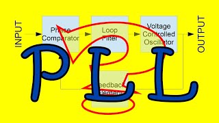
What is Phase Lock Loop (PLL)? How Phase Lock Loop Works ? PLL Explained

แชร์
ฝัง
  • เผยแพร่เมื่อ 16 ก.ค. 2024
  • In this video, the basics of the Phase Lock Loop (PLL) have been explained.
    By watching this video, you will learn the following topics:
    0:00 Introduction
    0:20 Applications of Phase Lock Loop
    1:24 How Phase Lock Loop Works
    3:30 Capture Range and Lock Range of PLL
    5:11 How Phase detector works? XOR Gate as Phase Detector
    9:30 Phase Frequency Detector
    13:41 PLL as Frequency Synthesizer
    What is Phase Lock Loop :
    The Phase Lock Loop is the control loop or the control system which maintains the same phase between the input or the reference signal and the output signal.
    The Phase Lock Loop consist of three basic blocks:
    1) Phase Detector
    2) Loop Filter (Low Pass Filter)
    3) Voltage Controlled Oscillator (VCO)
    Working of PLL:
    Phase Detector :
    The Phase detector detects the phase difference between the VCO and the input, or the reference signal.
    Based on the phase difference, it generates the error signal.
    At RF frequencies, the balanced mixer is used as a phase detector, while for the digital signal, the XOR gate and Phase Frequency Detector is used for the phase detection.
    Low Pass Filter:
    The low pass filter removes the high-frequency components from the error signal and generates the error voltage. The error voltage is fed to the VCO for the frequency correction.
    Voltage Controlled Oscillator:
    Based on the Control Voltage, the output frequency of the VCO can be controlled around the center frequency.
    Based on the error voltage, the output frequency of the VCO changes until the VCO frequency is equal to the input frequency.
    Lock condition:
    When the VCO frequency is the same as the input frequency and there is no phase difference or the constant phase difference between the two signals then the loop is said to be in the lock condition.
    Capture Range of PLL :
    Capture range is the range of input frequencies around the VCO center frequency onto which the loop can lock when starting from the unlocked condition.
    Lock Range of PLL :
    It is the range of input frequencies over which the loop remains in the lock condition once it has captured the input signal.
    Applications of PLL :
    1) Frequency Synthesizers and tone generation
    2) System Clock generation and for Clock distribution in processors
    3) For Synchronization and demodulation in the communication system
    4) Jitter and Noise reduction
    5) Clock Recovery
    In this video, the different building blocks of the PLL and the basic working of the loop is explained.
    The link of the other useful videos:
    1) Voltage Controlled Oscillator
    • Voltage Controlled Osc...
    2) Low Pass Filter
    • RC Low Pass Filter Exp...
    This video will be helpful to everyone in understanding what is Phase Lock Loop and how it works?
    Follow my second channel:
    / @allaboutelectronics-quiz
    Follow me on Facebook:
    / allaboutelecronics
    Follow me on Instagram:
    / all_about.electronics
    Music Credit:
    www.bensound.com/
    #PLL
    #PhaseLockLoop
  • วิทยาศาสตร์และเทคโนโลยี

ความคิดเห็น • 96

  • @ALLABOUTELECTRONICS
    @ALLABOUTELECTRONICS  4 ปีที่แล้ว +32

    The timestamps for the different topics covered in the video:
    0:20 Applications of Phase Lock Loop
    1:24 How Phase Lock Loop Works
    3:30 Capture Range and Lock Range of PLL
    5:11 How Phase detector works? XOR Gate as Phase Detector
    9:30 Phase Frequency Detector
    13:41 PLL as Frequency Synthesizer

    • @108ahah
      @108ahah 4 ปีที่แล้ว +2

      Thank you!

  • @sss2393
    @sss2393 3 ปีที่แล้ว +11

    thank god i found your channel, understood ever bit of it. And you had videos on every topic related to my queries, cant thank you enough, Keep growing

  • @hindskn
    @hindskn 3 ปีที่แล้ว +10

    Haven’t seen this stuff in years. Very clear. Thank you!

  • @alexandermcinnes2313
    @alexandermcinnes2313 3 ปีที่แล้ว +7

    Good video explaining the basic components of the PLL, my lecturers literally just assume you get it without explaining anything!

  • @frankreiserm.s.8039
    @frankreiserm.s.8039 3 ปีที่แล้ว +16

    You are a great electrical engineer and teacher. I never understood how an RC circuit could be a resonant circuit, such as in the Wein Bridge. I only understand how LC circuits, with the flywheel effect, can be resonant frequency tank circuits.

    • @akhilnandan5516
      @akhilnandan5516 ปีที่แล้ว +1

      RC circuit cannot produce resonance!!

  • @agstechnicalsupport
    @agstechnicalsupport ปีที่แล้ว +2

    A really great video on phase locked loops ! Thank you for sharing.

  • @denebvegaaltair1146
    @denebvegaaltair1146 2 ปีที่แล้ว +3

    Your videos are how I pass my assignments

  • @mahnoorsami8623
    @mahnoorsami8623 4 ปีที่แล้ว +2

    Much needed video on speech locked loop

  • @francescoavallone-xg7vt
    @francescoavallone-xg7vt 11 หลายเดือนก่อน

    Thank you very much for your contents. I am a computer engineer with a passion for the electronics and I decided to pursue my career as Firmware engineer. Fortunately with your contents, I am having the opportunity to understand each possible component of a micro. Please, keep going 😀

  • @chandanjain1728
    @chandanjain1728 3 ปีที่แล้ว +2

    such a crystal clear explanation sir.thank you

  • @nishantsahu11
    @nishantsahu11 4 ปีที่แล้ว +4

    very good explanation, thanks for clarifying my doubt

  • @ashwin372
    @ashwin372 ปีที่แล้ว +2

    much better than my college lecturers . College was a waste

  • @pravinahshasidharan
    @pravinahshasidharan 3 ปีที่แล้ว +2

    Thank you very much for the clear explanation.

  • @Joe-xl8fh
    @Joe-xl8fh 2 ปีที่แล้ว +1

    Excellent demonstration!

  • @jyothico8812
    @jyothico8812 3 ปีที่แล้ว +1

    Thank you for the clear explanation sir!

  • @tomc642
    @tomc642 ปีที่แล้ว +2

    As always excellent. Phase detectors ate also used in instrumentation. I never could figure how phase sensitive demodulation works when the input is an analog signal, like in signal conditioning for an accelerometer.

  • @AniketSalunkhe1995
    @AniketSalunkhe1995 3 ปีที่แล้ว +1

    Really Useful. Thanks for such clear explanation

  • @alonsechan8178
    @alonsechan8178 3 ปีที่แล้ว +2

    Great explanation, thank you !

  • @hri124
    @hri124 3 ปีที่แล้ว +1

    This was really good explanation! Thanks!

  • @Vinaykumar-bf8hj
    @Vinaykumar-bf8hj 2 ปีที่แล้ว +2

    Awesome explaination ..helped to prepare for interview

  • @theonlysiva9547
    @theonlysiva9547 4 ปีที่แล้ว +5

    Thanks you very much sir, keep doing ece subjects tutorials.

  • @dhirajkumarsahu999
    @dhirajkumarsahu999 4 ปีที่แล้ว +4

    Thank You, Sir!

  • @Parirash123
    @Parirash123 4 ปีที่แล้ว +1

    Very good explanation. Thank you

  • @trantien3927
    @trantien3927 2 ปีที่แล้ว +1

    Very clear video and content.
    Thanks

  • @unebonnevie
    @unebonnevie 2 หลายเดือนก่อน +1

    Well done on explaining PLL!

  • @saurabhtrivedi6181
    @saurabhtrivedi6181 2 ปีที่แล้ว +2

    Thanks man, it was very nice and easy to understand :)

  • @pro-eq9oy
    @pro-eq9oy ปีที่แล้ว +1

    Great things I got more knowledge and understand about electronics... Thanks lot

  • @anoop9416042368
    @anoop9416042368 3 ปีที่แล้ว +1

    Thank you so much for this knowledge sharing

  • @ashishtayade047
    @ashishtayade047 6 หลายเดือนก่อน +1

    Thank you sir very nice gide & very nice best information phase lock loop (PLL) teaching video.👍

  • @rollis97
    @rollis97 4 ปีที่แล้ว +2

    thanks, very good video!

  • @bangarrajulingampalli1982
    @bangarrajulingampalli1982 3 ปีที่แล้ว +1

    EXCELLENT VIDEO, IT IS EXCITING TO VIEW, KEEP IT UP

  • @zardouayassir7359
    @zardouayassir7359 4 ปีที่แล้ว +7

    The last topic about the frequency synthesizer does not make sense to me. For example, you say that the PLL can be used to divide the input frequency by N. Yet, this requires a frequency divider to be placed before the phase detector. The output of this frequency divider is the same as the output of the PLL. In other words, if I remove the PLL and keep the frequency divided, I can still get a signal whose frequency is divided by N. So, what's the point of the PLL in such a situation ??
    Thanks for the explanation though!

  • @ArjanvanVught
    @ArjanvanVught 4 ปีที่แล้ว +1

    Thank you!

  • @prajwalbp1087
    @prajwalbp1087 2 ปีที่แล้ว +1

    Awesome explaination

  • @user-qz6lq4yn8v
    @user-qz6lq4yn8v 2 ปีที่แล้ว +3

    Great really it was needed

  • @Official-tk3nc
    @Official-tk3nc 4 ปีที่แล้ว +1

    This channel needs 1 Million subs....Agree??????:):):):)

  • @vikramyogan2501
    @vikramyogan2501 3 ปีที่แล้ว +1

    Very well explained 👍🏻♥️🙏🏻

  • @lwalida8905
    @lwalida8905 3 ปีที่แล้ว

    Thank you so much my friend

  • @ManojKumar-jw5ys
    @ManojKumar-jw5ys 3 ปีที่แล้ว

    THANK YOU BUDDY !!

  • @erfan_zar
    @erfan_zar 3 ปีที่แล้ว +1

    Awesome!!!!Thanks

  • @MrRijubratapal
    @MrRijubratapal 4 ปีที่แล้ว +1

    Very lucid explanation.

  • @chethanvenkatesh7901
    @chethanvenkatesh7901 4 ปีที่แล้ว +2

    Thanks you so much.. PD - averaging of phase difference gave me good insight on PD and PFD

  • @ahmetyildiz1306
    @ahmetyildiz1306 3 ปีที่แล้ว +1

    master You are the best

  • @notchskills7897
    @notchskills7897 3 ปีที่แล้ว

    Thanks so much

  • @rakeshshrivastava4249
    @rakeshshrivastava4249 3 ปีที่แล้ว

    Thanks, very nice,

  • @GauravGupta-pb8mk
    @GauravGupta-pb8mk 3 ปีที่แล้ว

    Thank you sir

  • @LightningHelix101
    @LightningHelix101 3 ปีที่แล้ว +2

    Do you think there are good empirical models for oscillators? The unsatisfying problem with PLLs is that no one can tell you how to qualify an oscillator’s performance without one. I’m reading through Razavi’s recent book on PLLs now. Jittery is largely incalculable for free-running oscillators. The negative resistance from the feedback devices has a nonlinear Gm moving poles in and out of perfect dampening. The changing bias on capacitors also moves this operating point as well as the dielectric saturates. Reducing the need for the distortable Gm can be accomplished by raising the quality factor of Ls and Cs, but I have yet to find a useful analytic expression for jitter.

  • @Suiiiiiiiiiiii.
    @Suiiiiiiiiiiii. 2 หลายเดือนก่อน +1

    thanks u amigo

  • @Shiny_Mewtwo
    @Shiny_Mewtwo 3 ปีที่แล้ว

    Thank you

  • @brandynalbrecht772
    @brandynalbrecht772 3 ปีที่แล้ว +1

    Hey could you do a video on a Delay Locked Loop? With the multiplexers and ring oscillator/ chain system explained?

  • @poojashah6183
    @poojashah6183 4 ปีที่แล้ว +3

    Best👌🏻👌🏻

  • @Opticx25
    @Opticx25 2 ปีที่แล้ว

    Thank you soo much sir

  • @jose421tal1
    @jose421tal1 4 หลายเดือนก่อน

    Beautiful and clear lecture !
    However I see saturating race issue on both FET if the AND gate is slow when both UP and DOWN are High logic.
    If the and gate is slow, and both UP and DOWN logic are high,
    there is fraction of time with a short circuit between Vdd to Vss trough saturation of both P_fet to N_fet.
    I would add to both P_fet and N_fet sources a low value serial resistor like ~50 Ohm to damp the overcurrent in case of any AND gate issue as protection against short circuit and cause possible overstress to fet /damage.
    Best Regards
    Jose Tal

  • @GokulGokul-iz2to
    @GokulGokul-iz2to 3 ปีที่แล้ว

    Thank u sir

  • @user-lh7sk8js9d
    @user-lh7sk8js9d 4 ปีที่แล้ว

    Nice.

  • @MrMagic-fc4dn
    @MrMagic-fc4dn 3 หลายเดือนก่อน

    I need to know which software u use to create all these schematics and characteristics/graphs :0
    Great video!

  • @rohitpathak5313
    @rohitpathak5313 2 ปีที่แล้ว +4

    Your videos are more informative than my college professor's lecture.
    Suggestion: You must use a bright and big cursor(bigger than the present one) because it is unable to find at where you are pointing on the screen.
    👍

    • @ALLABOUTELECTRONICS
      @ALLABOUTELECTRONICS  2 ปีที่แล้ว +1

      I have already considered that suggestion and now the size of the cursor is increased in the new videos.

  • @PradeepKing143
    @PradeepKing143 2 ปีที่แล้ว +7

    Increase the size of cursor to clear about where you are explaining exactly

  • @gago3001
    @gago3001 10 วันที่ผ่านมา

    I want to follow up on your last example of the frequency multiplier. The f_o is at 10MHz, so the error voltage should be high to increase the f_o frequency. However, the phase detector see that the 2 input signals have the same frequency, so the error voltage should be small. There is a contradiction here. Could you explain further?

  • @zinhaboussi
    @zinhaboussi ปีที่แล้ว

    nice

  • @TELEZUD
    @TELEZUD 4 ปีที่แล้ว +1

    Super! Thanks!

  • @aryangiri4777
    @aryangiri4777 2 ปีที่แล้ว +1

    Sir is there difference in PLL 565 and the one you explained

  • @kalanamadusara4097
    @kalanamadusara4097 2 หลายเดือนก่อน

    what is the use of the feedback divider?

  • @Crazyforelectronics
    @Crazyforelectronics 4 ปีที่แล้ว

    can we connect nmos instead of pmos

  • @LL-ue3ek
    @LL-ue3ek ปีที่แล้ว

    It's somewhat straight forward to lock two square waves. But is there a known way to lock two sine waves?

  • @emilcalilov8910
    @emilcalilov8910 4 ปีที่แล้ว +1

    Thanks, amazing. Do you have videos on flip flop, clock signals etc?

  • @mahnoorsami8623
    @mahnoorsami8623 4 ปีที่แล้ว

    Can u expllain in video speech locked loop method

  • @Yun-bm3iv
    @Yun-bm3iv 4 ปีที่แล้ว +3

    Thank you sir!
    Could you please make videos about I2C,SPI interfaces?

    • @ALLABOUTELECTRONICS
      @ALLABOUTELECTRONICS  4 ปีที่แล้ว +3

      Yes, soon I will make it.

    • @ArjanvanVught
      @ArjanvanVught 4 ปีที่แล้ว +1

      @@ALLABOUTELECTRONICS Then also EIA-485-A standard and the effect of the resistor terminators in special

  • @user-nn5wf3fk4g
    @user-nn5wf3fk4g 5 หลายเดือนก่อน

    can i increase the pico rp2040 freq with pll

  • @gago3001
    @gago3001 10 วันที่ผ่านมา

    so when the PLL is locked, the phase and frequency difference is minimized -> the error voltage will be minimized -> how can the f_o can increase to meet f_in?

  • @KRISRONIN
    @KRISRONIN 3 ปีที่แล้ว

    SIR CAN U SEPARATELY MAKE A VDEO ABOUT PHASE SHIFT I CANT UNDERSTAND

  • @tony87419
    @tony87419 4 ปีที่แล้ว +2

    Excuse me , sir. Is there any wrong with the capture range of PLL at 4:42
    I think the center of the capture range is f0 , Please reply , Thanks !

  • @mindf_ckingtruth3395
    @mindf_ckingtruth3395 4 ปีที่แล้ว +2

    At 12:38 you accidently spoke the vive versa
    if up output is high then output voltage will be pulled up from VDD/2 to VDD.

  • @CanQuangTruong
    @CanQuangTruong ปีที่แล้ว +1

    Hi teacher, I am confused about the capture range and lock range. I suppose that when the input frequency is in the lock range then it can be locked by PLL and now the output of PLL is f_R, if it is out of lock range it is no-lock. Why do we need the captured range because the lock range is enough for PLL?

    • @ALLABOUTELECTRONICS
      @ALLABOUTELECTRONICS  ปีที่แล้ว

      Lock range comes into picture when the loop is already in the locked condition. The lock range is the range of input frequencies over which the loop can remain in the locked condition.
      The capture range comes into picture when the loop is not locked. The capture range is the range of input frequencies over which the loop can get locked when it is in unlock condition. Please watch the video from 3:30 onwards. You will get it now.

  • @umayaraj7674
    @umayaraj7674 4 ปีที่แล้ว +2

    Hi , Is pll is mixed signal circuits?

  • @satirthapaulshyam7769
    @satirthapaulshyam7769 ปีที่แล้ว

    So 12:50 ei timee ora freq ta same korbe and phase difference theke jabe but oita constant hoee jabe. It will not cng. Etai amra chaisi phase locked hoi phase diff 0 naile const

  • @te9781
    @te9781 ปีที่แล้ว +1

    Something really driving me insane !! If we used PLL in AM demodulation receiver ..in the PLL mixer the AM signal multiply by fc after the LPF output the subtraction will give the information signal which is not a zero value of constant voltage if local fc not matching received fc

  • @ajingolk7716
    @ajingolk7716 6 หลายเดือนก่อน

    Capture range and Lock range?

  • @hydrogenkhan8728
    @hydrogenkhan8728 2 ปีที่แล้ว +1

    Good job. You are a good teacher and real "Gandoo"

  • @ramalakshmikola1652
    @ramalakshmikola1652 3 ปีที่แล้ว +1

    Plz..provide the derivation....deltapi=0

  • @friosminsysnym
    @friosminsysnym 2 ปีที่แล้ว

    Technical wise no problem, but still don’t know why the applications use PLL

  • @Vishalkumar-mu5hy
    @Vishalkumar-mu5hy 2 ปีที่แล้ว

    Who is here after lookin a radio review.

    • @lovely_ji
      @lovely_ji 2 ปีที่แล้ว

      No one,, and u need to grow up 🙄

  • @rishitgome2073
    @rishitgome2073 2 ปีที่แล้ว

    Oh! wrong pll

  • @princyjoseph3408
    @princyjoseph3408 2 ปีที่แล้ว

    Thank you