This was a great video to watch! I'm just refreshing my memory since I haven't ran a CNC for a LONG LONG TIME... This channel is making it all come back! Thanks!!
IMO the way we do it in our shop. We touch off all tools off the top of the part with peace of paper. On all the newer haas and the older haas mills. Wiggle paper T1 come down in the Z till the tool touches the paper (.001) In G54 work area (Z) hit part zero set button. Now MDI call up T2 Wiggle paper T2 come down in the Z till the tool touches the paper (.001) now in your tool off set page. ON T2 you push (tool offset measure) button. Then push (NEXT TOOL) button and it will call up T3 Then repeat the steps that you did for tool 2. Make sure to NOT forget your CUTTER COMP if your using END MILLS. Now I did not go to school or college. I learned the hard way and made many mistakes. And still do today. But stay focused. Keep the burning to want to learn and progress. I have been doing machine work for 10 years now and still watch videos like these all the time.
after 10:49 you said to measure the tools you are using for the day off the top of the part, so why use the table if your just going to redo the process off of the part?
How do you control mismatch from running two different vices for one part. Like g54 and g55. 54 will do one side of the part and 55 dose the other. How do you make sure it matches up
Great work Jeff. I have been trying to set up and run a 1980 Kitumari mill machine with a Fanuc 10M control. I am now having problems with the tools retracting up into the plus side when it gets to the G43 H line. I have never worked an old control like this and my Mastercam program does not work when I load it into the control. As you can see my program below, my spindle flat without the tool in it is -16.013 to top of part zero from the Z machine home position. With tool 4 in it, it is -10.661 to top part zero. I have 5.352 in my tool 4 length geometry. And I have 3.904 in my tool 2 geometry for circular milling counterbore. I can`t get this program to run right without the spindle retracting at the G43 line and I can`t get the tools to decend to the same reference point (Z.1) from top of part to start the cycle. Does the machine reference from the spindle flat to the top of the part and go into the G54 workshift and/or does that number or another number go into the start of the program as a reference for all tools? The programs run good on newer controls but this old control has to have precise ways to read. Please let me know how to set the machine work coordinate settings with the correct way to set the tool geometry. I have looked everywhere to correct this but the machine will not operate correctly. I have included the mill program as well as it seems the tool geometry will not allow the tool to go past 2 inches from the top of the part. I thnk this has to do with some G90. G92, G54 code. N100G92X1.125Y0Z-10.661 N101G90G0Z-10.661T4M6 N102G28X0Y0 N103S1200M3 N104G43H4 N105G90G0G54X1.125Y0Z1. N110G99G82Z-1.2419R.1F20. N112X3.832 N114G80 N116M5 N118G91G28Z0. N120Z0 N122M01 N1G28X0Y0Z0 Mo1 N2T2M6 N3G92X1.125Y0Z12.109 N4G0G40G49G80G90G92G99 N5S1750M3 N6G90G0X1.125Y0Z.2 N6G54G43H2Z-4. N8G0G92G54X1.125Y0Z.2 N12G01G90G54X1.15Y0Z.1F20. N131G90G17G0D22 N132G17G3X1.15Y.025R.028F6. N134X1.125Y.05I-.025J0. N136X1.075Y0.I0.J-.05 N138X1.125Y-.05I.05J0. N140X1.175Y0.I0.J.05 N142X1.125Y.05I-.05J0. N144X1.1Y.025I0.J-.025 N146G1X1.125Y0. N148G0Z.25 N150Z.1 N152G1Z-.4F15. N154X1.15Y.025F25. N156G3X1.125Y.05I-.025J0. N158X1.075Y0.I0.J-.05 N160X1.125Y-.05I.05J0. N162X1.175Y0.I0.J.05 N164X1.125Y.05I-.05J0. N166X1.1Y.025I0.J-.025 N168G1X1.125Y0. N170G0Z.25 N172Z.1 N174G1Z-.6F15. N176X1.15Y.025F25. N178G3X1.125Y.05I-.025J0. N180X1.075Y0.I0.J-.05 N182X1.125Y-.05I.05J0. N184X1.175Y0.I0.J.05 N186X1.125Y.05I-.05J0. N188X1.1Y.025I0.J-.025 N190G1X1.125Y0. N192G0Z.25 N194X4.957 N196Z.1 N198G1Z-.2F15. N200X4.982Y.025F25. N202G3G17X4.957Y.05I-.025R.032F12. N204X4.907Y0.I0.J-.05 N206X4.957Y-.05I.05J0. N208X5.007Y0.I0.J.05 N210X4.957Y.05I-.05J0. N212X4.932Y.025I0.J-.025 N214G1X4.957Y0. N216G0Z.25 N218Z.1 N220G1Z-.4F15. N222X4.982Y.025F25. N224G3X4.957Y.05I-.025J0. N226X4.907Y0.I0.J-.05 N228X4.957Y-.05I.05J0. N230X5.007Y0.I0.J.05 N232X4.957Y.05I-.05J0. N234X4.932Y.025I0.J-.025 N236G1X4.957Y0. N238G0Z.25 N240Z.1 N242G1Z-.6F15. N244X4.982Y.025F25. N246G3X4.957Y.05I-.025J0. N248X4.907Y0.I0.J-.05 N250X4.957Y-.05I.05J0. N252X5.007Y0.I0.J.05 N254X4.957Y.05I-.05J0. N256X4.932Y.025I0.J-.025 N258G1X4.957Y0. N260G0Z.25 N262M5 N264G91G28Z0. N266G28X0.Y0.Z0 N268M30 %
If the work offset G54 z axis is set at 5.730 (13:50) at the top of the work piece surface then the table is zero so if I programmed G01 Z-.50 the tool will try to machine the table a half inch into its surface...right.... this is the most confusing video the G54 z axis should be zero with the tool at its surface and any movement into the part should be negative. what am I missing here??? all movement from z home is negative MCS so if the work surface is positive then the table has to be zero because of work off set???????????????????
richard manross You are right Richard. Can you look at my post and see what I am doing wrong? I can`t find anyone who has run a 1980 Fanuc 10M and I am having problems setting the machine up with the g54 machine coordinate system and each tool measurement.
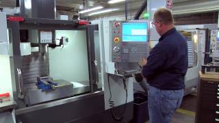
Thanks for the information, it's really helpful. But try to highlight your screen in the camera and focus on screen so we can see those numbers and values there clearly.
Easier way = touch all tools off on 123 block hitting tool measure button with each. DO NOT subtract 3 inches. DO NOT worry about negatives or positives. USE ANY tool previously touched off and touch it to the 123 block top again. HIT OPERATOR MEASURE MODE Button, this mode is under different names on different machines but they all have it. ZERO USER MEASURE Z and move tool to top of workpiece. The machine perfectly measures the distance for you and you can manually enter that measurement into your desired work offset for Z. I think this method is the safest and most error resistant method for tool offsets while preserving tool offsets through workpiece changes. Tools will not need to be retouched for a height change you simply touch off the 123 block again with any tool and remeasure to the top of your new part with user measurement mode from a forced Z zero on the top of the 123 block. Simply enter that measurement to your new Z offset and you're ready to machine.
what's the point in touching off on a "common surface" like the table in this demonstration. Why not just touch off of the top of the part and save a lot of time? I don't understand...
+Allison Jones, there are many different ways for touching off tools. You just use which ever way that you feel comfortable with. In this video, he uses the table surface as a reference point for all tools because this table surface will never changed. For example, if you break the tool during a machine cycle then you replace the new tool and again touch off the new to the table surface. If you touched off all the tools on top of the part then you do the facing.........In the worst case scenario, if you break a tool during this machine cycle and you might not know where is you original reference surface.
Yes I agree. Only touch on the top of the part and that's it. What the use of using the table and after all he just uses the machine or absolute value in the position table and subtract.
He should touch the spindle off of the 1-2-3 block first and set G54 Z. All tools after that will give you a positive value that is the actual length. Keep it simple.
Yeah, maybe he can measure the exact lenght of any tool (I recomended hammerindicator) and then touch of 1-2-3 block and set there G54 Z. Then he can touch every tool which he want to use in program on this block and set the lenghts of theese tools to the tool offset table (positive value). Then he can put in the spindle a hammer indicator again and touch off the top face of the part or maybe anothore surface which he want to use as a face for setting G54 Z. Every time he touched another part with another heigh he do not need to measure his tools again (if he use the same tools). This means that tools are measured from the spindle face (if the Z lenght value is positive)
That was basically the first option he stated. Then he decided to go with the more common and horrible "HAAS" way of setting tool offsets, cuz you know, HAAS tech pre-dates machines made in the 80s. I'm sure someday they'll catch up or hopefully just go belly up... haha.
it is easier to use Operator screen and use "origin" bottom to zero out the axis(x, y, z, a), save a lot of time from punching number in the calculator.
I don't know what your table looks like but mine is FULL of chips. That is Kurt vise, adjust that! Way to much work. PAPER! 123 block? This somehow reduces TLO setting error? The owner says to me: "This machine is filthy!" I said yeah, cool right? He laughed and walked away. He knows. Solid basics none the less. You will never hear me bitch about someone putting in extra effort or trying to teach. I'm good over all.
what a bone headed way to explain tool settings ALWAYS set up off the parts!!! Using z axis work offsets is confusing as hell The only reason to do this is for mass production with multiple fixtures and work offsets with a magazine full of tools you rarely change but for every day short runs NO


This was a great video to watch! I'm just refreshing my memory since I haven't ran a CNC for a LONG LONG TIME... This channel is making it all come back! Thanks!!
IMO the way we do it in our shop. We touch off all tools off the top of the part with peace of paper.
On all the newer haas and the older haas mills.
Wiggle paper
T1 come down in the Z till the tool touches the paper (.001)
In G54 work area (Z) hit part zero set button.
Now MDI call up T2
Wiggle paper
T2 come down in the Z till the tool touches the paper (.001)
now in your tool off set page.
ON T2 you push (tool offset measure) button.
Then push (NEXT TOOL) button and it will call up
T3
Then repeat the steps that you did for tool 2.
Make sure to NOT forget your CUTTER COMP if your using END MILLS.
Now I did not go to school or college. I learned the hard way and made many mistakes.
And still do today.
But stay focused. Keep the burning to want to learn and progress.
I have been doing machine work for 10 years now and still watch videos like these all the time.
Thank you sir i had learn from your videos.Please keep feeding your the best teacher I have found.
Thank you so much for this information. Please keep feeding your the best teacher I have found. This can help alot of people. Thank you very much.
after 10:49 you said to measure the tools you are using for the day off the top of the part, so why use the table if your just going to redo the process off of the part?
How do you control mismatch from running two different vices for one part. Like g54 and g55. 54 will do one side of the part and 55 dose the other. How do you make sure it matches up
Great work Jeff. I have been trying to set up and run a 1980 Kitumari mill machine with a Fanuc 10M control. I am now having problems with the tools retracting up into the plus side when it gets to the G43 H line. I have never worked an old control like this and my Mastercam program does not work when I load it into the control. As you can see my program below, my spindle flat without the tool in it is -16.013 to top of part zero from the Z machine home position. With tool 4 in it, it is -10.661 to top part zero. I have 5.352 in my tool 4 length geometry. And I have 3.904 in my tool 2 geometry for circular milling counterbore. I can`t get this program to run right without the spindle retracting at the G43 line and I can`t get the tools to decend to the same reference point (Z.1) from top of part to start the cycle. Does the machine reference from the spindle flat to the top of the part and go into the G54 workshift and/or does that number or another number go into the start of the program as a reference for all tools? The programs run good on newer controls but this old control has to have precise ways to read. Please let me know how to set the machine work coordinate settings with the correct way to set the tool geometry. I have looked everywhere to correct this but the machine will not operate correctly. I have included the mill program as well as it seems the tool geometry will not allow the tool to go past 2 inches from the top of the part. I thnk this has to do with some G90. G92, G54 code.
N100G92X1.125Y0Z-10.661
N101G90G0Z-10.661T4M6
N102G28X0Y0
N103S1200M3
N104G43H4
N105G90G0G54X1.125Y0Z1.
N110G99G82Z-1.2419R.1F20.
N112X3.832
N114G80
N116M5
N118G91G28Z0.
N120Z0
N122M01
N1G28X0Y0Z0
Mo1
N2T2M6
N3G92X1.125Y0Z12.109
N4G0G40G49G80G90G92G99
N5S1750M3
N6G90G0X1.125Y0Z.2
N6G54G43H2Z-4.
N8G0G92G54X1.125Y0Z.2
N12G01G90G54X1.15Y0Z.1F20.
N131G90G17G0D22
N132G17G3X1.15Y.025R.028F6.
N134X1.125Y.05I-.025J0.
N136X1.075Y0.I0.J-.05
N138X1.125Y-.05I.05J0.
N140X1.175Y0.I0.J.05
N142X1.125Y.05I-.05J0.
N144X1.1Y.025I0.J-.025
N146G1X1.125Y0.
N148G0Z.25
N150Z.1
N152G1Z-.4F15.
N154X1.15Y.025F25.
N156G3X1.125Y.05I-.025J0.
N158X1.075Y0.I0.J-.05
N160X1.125Y-.05I.05J0.
N162X1.175Y0.I0.J.05
N164X1.125Y.05I-.05J0.
N166X1.1Y.025I0.J-.025
N168G1X1.125Y0.
N170G0Z.25
N172Z.1
N174G1Z-.6F15.
N176X1.15Y.025F25.
N178G3X1.125Y.05I-.025J0.
N180X1.075Y0.I0.J-.05
N182X1.125Y-.05I.05J0.
N184X1.175Y0.I0.J.05
N186X1.125Y.05I-.05J0.
N188X1.1Y.025I0.J-.025
N190G1X1.125Y0.
N192G0Z.25
N194X4.957
N196Z.1
N198G1Z-.2F15.
N200X4.982Y.025F25.
N202G3G17X4.957Y.05I-.025R.032F12.
N204X4.907Y0.I0.J-.05
N206X4.957Y-.05I.05J0.
N208X5.007Y0.I0.J.05
N210X4.957Y.05I-.05J0.
N212X4.932Y.025I0.J-.025
N214G1X4.957Y0.
N216G0Z.25
N218Z.1
N220G1Z-.4F15.
N222X4.982Y.025F25.
N224G3X4.957Y.05I-.025J0.
N226X4.907Y0.I0.J-.05
N228X4.957Y-.05I.05J0.
N230X5.007Y0.I0.J.05
N232X4.957Y.05I-.05J0.
N234X4.932Y.025I0.J-.025
N236G1X4.957Y0.
N238G0Z.25
N240Z.1
N242G1Z-.6F15.
N244X4.982Y.025F25.
N246G3X4.957Y.05I-.025J0.
N248X4.907Y0.I0.J-.05
N250X4.957Y-.05I.05J0.
N252X5.007Y0.I0.J.05
N254X4.957Y.05I-.05J0.
N256X4.932Y.025I0.J-.025
N258G1X4.957Y0.
N260G0Z.25
N262M5
N264G91G28Z0.
N266G28X0.Y0.Z0
N268M30
%
nice work
If the work offset G54 z axis is set at 5.730 (13:50) at the top of the work piece surface then the table is zero so if I programmed G01 Z-.50 the tool will try to machine the table a half inch into its surface...right.... this is the most confusing video the G54 z axis should be zero with the tool at its surface and any movement into the part should be negative. what am I missing here??? all movement from z home is negative MCS so if the work surface is positive then the table has to be zero because of work off set???????????????????
richard manross You are right Richard. Can you look at my post and see what I am doing wrong? I can`t find anyone who has run a 1980 Fanuc 10M and I am having problems setting the machine up with the g54 machine coordinate system and each tool measurement.
I am willing to look at the issue, just send me pictures with the tool offsets and work offsets screens.
When you remove the tool does the machine lose the tool measurements ?
No. The only way to lose the tool offset is if you manually delete it
Thanks for the information, it's really helpful.
But try to highlight your screen in the camera and focus on screen so we can see those numbers and values there clearly.
Can someone explain why it's a negative value? Is it not 2" above the table?
Easier way = touch all tools off on 123 block hitting tool measure button with each. DO NOT subtract 3 inches. DO NOT worry about negatives or positives. USE ANY tool previously touched off and touch it to the 123 block top again. HIT OPERATOR MEASURE MODE Button, this mode is under different names on different machines but they all have it. ZERO USER MEASURE Z and move tool to top of workpiece. The machine perfectly measures the distance for you and you can manually enter that measurement into your desired work offset for Z. I think this method is the safest and most error resistant method for tool offsets while preserving tool offsets through workpiece changes. Tools will not need to be retouched for a height change you simply touch off the 123 block again with any tool and remeasure to the top of your new part with user measurement mode from a forced Z zero on the top of the 123 block. Simply enter that measurement to your new Z offset and you're ready to machine.
Very well done Jeff Thanks
yea.... from here on out you shall be professor Block
you are the best
Why don’t use high gauge . Making it easy before I did . Different kind machines i don’t know function
what's the point in touching off on a "common surface" like the table in this demonstration. Why not just touch off of the top of the part and save a lot of time? I don't understand...
+Allison Jones, there are many different ways for touching off tools. You just use which ever way that you feel comfortable with. In this video, he uses the table surface as a reference point for all tools because this table surface will never changed. For example, if you break the tool during a machine cycle then you replace the new tool and again touch off the new to the table surface. If you touched off all the tools on top of the part then you do the facing.........In the worst case scenario, if you break a tool during this machine cycle and you might not know where is you original reference surface.
We do it like that in our firm.
Yes I agree. Only touch on the top of the part and that's it.
What the use of using the table and after all he just uses the machine or absolute value in the position table and subtract.
I wish i could go to school here. Whats cutter comp? Oh, you don't need it. Haas put it in the control just to fuck with you.
He should touch the spindle off of the 1-2-3 block first and set G54 Z. All tools after that will give you a positive value that is the actual length. Keep it simple.
Yeah, maybe he can measure the exact lenght of any tool (I recomended hammerindicator) and then touch of 1-2-3 block and set there G54 Z. Then he can touch every tool which he want to use in program on this block and set the lenghts of theese tools to the tool offset table (positive value). Then he can put in the spindle a hammer indicator again and touch off the top face of the part or maybe anothore surface which he want to use as a face for setting G54 Z. Every time he touched another part with another heigh he do not need to measure his tools again (if he use the same tools). This means that tools are measured from the spindle face (if the Z lenght value is positive)
That was basically the first option he stated. Then he decided to go with the more common and horrible "HAAS" way of setting tool offsets, cuz you know, HAAS tech pre-dates machines made in the 80s. I'm sure someday they'll catch up or hopefully just go belly up... haha.
it is easier to use Operator screen and use "origin" bottom to zero out the axis(x, y, z, a), save a lot of time from punching number in the calculator.
I don't know what your table looks like but mine is FULL of chips. That is Kurt vise, adjust that! Way to much work. PAPER! 123 block? This somehow reduces TLO setting error? The owner says to me: "This machine is filthy!" I said yeah, cool right? He laughed and walked away. He knows.
Solid basics none the less. You will never hear me bitch about someone putting in extra effort or trying to teach. I'm good over all.
I am glad he is not on my pay roll. Touch off the top of part and get
To work.
+Katherine lol,that's what i was thinking.thanks for saying it.....
That's how they taught us in school.
what a bone headed way to explain tool settings
ALWAYS set up off the parts!!! Using z axis work offsets is confusing as hell
The only reason to do this is for mass production with multiple fixtures and work offsets
with a magazine full of tools you rarely change
but for every day short runs NO
Mucho rollo para tomar alturas nada más, gracias pero tu video no sirve . Es mejor tomar Z de top pieza, el papelometro nunca pasara de moda jejeje