You might have been in emergencies in which your manager or a client needs you for a quick failure diagnosis of their tripped plant. If not, you will certainly be! 🙂 So knowing the structure of the electrical and control wiring diagrams would be super useful in those circumstances! To get more insights about the wiring diagram I strongly recommend watching the following videos: How to Read Electrical Diagrams 👉upmation.com/wiring-diagrams/ How to Read PLC Wiring Diagram 👉upmation.com/plc-wiring-diagram/
Hi, Noel! You're welcome! These numbers are to address various parts and equipment on different pages of the wiring diagram. If you wish to get more insights on this matter please watch this video or read its article here: ▶ upmation.com/wiring-diagrams/
Thank you for watching! The AS-interface master is a controller that controls its downstream instruments independently using the AS interface protocol which is a specific protocol for the field level of the automation system. At the same time, it is connected to the upstream bus of the control level to exchange some data to/from the higher level of the control system. For doing so, it converts the ASI to other Fieldbus protocols that are usually used by the control level such as (Ethernet, Profibus, etc.) I suggest you watch these two videos to get more insights: Distributed IO vs. Remote IO: th-cam.com/video/PxvDM0hhr-Q/w-d-xo.html Remote I/O System for Industrial Automation: th-cam.com/video/Fqx4Knk-TTQ/w-d-xo.html
Hi, Daniel! These documents are copyrighted and regardless of our desire to share them with you rest of our audience, we are not able to do that, unfortunately. Thank you for your understanding!
Hi Bitebo! Thank you for following up. We're going to publish a new video in the next week. As you are a member, you will become aware of the reasons of the delays and some good news soon, via the community.
Hi, there! These documents are copyrighted and regardless of our desire to share them with you rest of our audience, we are not able to do that, unfortunately. Thank you for your understanding!
Hi, Mohamed! These documents are copyrighted and regardless of our desire to share them with you rest of our audience, we are not able to do that, unfortunately. Thank you for your understanding!
Hey! Thank you for your comment! This video was meant to outline different parts of a standard wiring diagram. Following you can find more detailed instructions on electrical wiring diagrams: How to Read Electrical Diagrams ▶ upmation.com/wiring-diagrams/ How to Read PLC Wiring Diagram ▶ upmation.com/plc-wiring-diagram/
Not all the time, indeed! Just three times during around 13 minutes. But we are sorry and we will reduce the number of times. Thank you for your comment!
Unfortunately, this video is just a brief and superficial view on this complicated topic. I think, that the beginner will not understand practically anything. Maybe you should make longer videos with more explanations. Or many smaller videos with one video for each table of contents item (power distribution, exchanging signals, safety devices wiring, control network configuration and so on). Otherwise great graphics and realisation of idea. Good luck, guys!
Thank you for sharing you viewpoint! Yes, this video as you've already explained was exactly aimed at introducing the general outline of a standard wiring diagram to let the audience have an overview about what they are going to deal with. And we will continue with the details of each part, as you can see in the following videos: ▶ upmation.com/wiring-diagrams/ ▶ upmation.com/plc-wiring-diagram/ Please watch these videos as well and let us know what you think. Thank you!
@@Upmation Already watched these videos. They are a lot more informative and detailed. Hope the next videos will be as good as these or even better. Thank you!


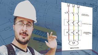


You might have been in emergencies in which your manager or a client needs you for a quick failure diagnosis of their tripped plant. If not, you will certainly be! 🙂
So knowing the structure of the electrical and control wiring diagrams would be super useful in those circumstances!
To get more insights about the wiring diagram I strongly recommend watching the following videos:
How to Read Electrical Diagrams 👉upmation.com/wiring-diagrams/
How to Read PLC Wiring Diagram 👉upmation.com/plc-wiring-diagram/
A drawing of great reference value. What software was used to draw this drawing and where can I download the drawing in the video
@@李彤-k3t Thank you for your compliment! The software that has been used to draw the diagram was EPLAN P8.2.
What an amazing topic! That is what we exactly wanted to see. Thank you very much!
Awesome! Lovely to hear that and glad we could help! Please share this video with your friends and colleagues in other social media. Thank you!
I work at Amazon as a Controls tech and this helps and is very similar to our setup. Very helpful and shared with my Team.
Perfect! Thank you for sharing! Stay tuned for more.
Which site do you work @mvdhcvargas5486. I work at EMA4 and previously BHX4 with a controls bias.
Thank you so much for this playlist im searching for this content and finally i got it thanks and pls continue this playlist.
You're very welcome! Thank you for your suggestion, we'll try to do that.
Hello, my friend!!! Today I'm in a good mood, I'm watching your videos) Thank you very much!!!
Hi Razer! You're most welcome! Thanks a lot for watching! Hope you liked that.
Very amazing video keep the good work
Thank you, Mohamed! Great to hear it was helpful.
another great tutorial video, thank you for sharing your knowledge.
You're very welcome and thanks a lot for watching!
Loved every second of it, keep it up! :)
Wow! Amazing! Thank you for watching and please share this video with your friends and colleagues in other social media.
another great video tutorial, thank you for sharing ypue knowledge.
You're very welcome! Thank you for watching!
Very informative video! Thank you so much
You are so welcome, Emad!
Keep it going! Go ahead! Don't stop! Please
Hey, Roma! Thank you for your comment! We will do our best! Although our time and resources are very limited.
wonderful Upmation
Thanks a lot!
Important and very useful information. Thanks for sharing this video
Many thanks, Golnaz! Great to hear that! Please stay tuned for more of these videos.
That's perfect. Keep the good work up. Thank you
Thanks a lot, and you're very welcome, Saeid! Will do! Please stay tuned.
❤beautifully u described everything .
impressive ,Thank you
Many thanks! Glad you liked it!
Good explanation brother 👌👌
Really good videos 👍
It realy means a lot to me
Excellent brief , keep creating videos like this benefit explain.
Thank you, Mohammad! We will do our best to provide you and other audience with the best contents possible!
Amazing 🤩
Have you got a link to the Safety relay you mention?
very useful👍
Thanks a lot! Great to hear that!
8:47 what is the meaning of rp1:a etc on the top of the Q7
Awesome 👍
Thank you! Cheers!
nice video
Very good,
What software was used for this drawing?
Very good
👏This is an amazing series Upmation and I hope you carry on with the good work.
Thanks a lot! We hope so.
The upper lines and number are denoted for what? Thanks for the knowledge
Hi, Noel! You're welcome! These numbers are to address various parts and equipment on different pages of the wiring diagram. If you wish to get more insights on this matter please watch this video or read its article here: ▶ upmation.com/wiring-diagrams/
Great 👍
Thank you for watching! Let us know if you have any suggestions or questions.
Nice video.
Thanks a lot!
Good video, may i get project file of this wiring diagrams?
incredible
Sir will you start electrical designing in Eplan software please ?
thank u very much,i have one request ,could please heavy automotive schematic diagrams explain, if any link
You're very welcome! Thank you for your suggestion. We'll try to do that.
Good video. What is this "ASI Master Device"?
Thanks.
Thank you for watching! The AS-interface master is a controller that controls its downstream instruments independently using the AS interface protocol which is a specific protocol for the field level of the automation system. At the same time, it is connected to the upstream bus of the control level to exchange some data to/from the higher level of the control system. For doing so, it converts the ASI to other Fieldbus protocols that are usually used by the control level such as (Ethernet, Profibus, etc.)
I suggest you watch these two videos to get more insights:
Distributed IO vs. Remote IO: th-cam.com/video/PxvDM0hhr-Q/w-d-xo.html
Remote I/O System for Industrial Automation: th-cam.com/video/Fqx4Knk-TTQ/w-d-xo.html
@@Upmation Thanks for your prompt reply. Keep it up.
Can you do a video on safety relays? Thanks
Thanks for your suggestion! We will definitely consider that.
Hello sir, what software make this drawing ?
EPLAN was the software that this drawing has been designed with.
Awesome
Thank you!
Pleas tell me the software
Hi @upmation You guys should put the link for the drawings
Hi, Daniel! These documents are copyrighted and regardless of our desire to share them with you rest of our audience, we are not able to do that, unfortunately. Thank you for your understanding!
software drawing?
Hello Upmation. It's 3 months now and we are still waiting for a new video upload. Thanks for your educational videos.
Hi Bitebo! Thank you for following up. We're going to publish a new video in the next week.
As you are a member, you will become aware of the reasons of the delays and some good news soon, via the community.
Could you tell us what's free program to create electric diagrams?
Thank you.
Hi, Wilson! Unfortunately, we are not aware of any free software.
@@Upmation Thank you.
qelectrotech
DesignSpark Electrical
@Alejandro Alvarado Thank you.
Please make a video about safety switch
Thanks for your suggestion! Sounds like a great idea for the future videos.
@@Upmation I'm looking forward to it
Waring normally open normally close
Can you please share the schematic diagram pdf
Regrettably, accessing this document is not feasible as it is protected by copyright. Thanks for your understanding.
@@Upmation okay 👍
can you please upload for us the pdf that you used in video ??
Hi, there! These documents are copyrighted and regardless of our desire to share them with you rest of our audience, we are not able to do that, unfortunately. Thank you for your understanding!
@@Upmation ok. Thank you ❤️
@Upmation it's okay, I understand. Can you please even tell the series number of the machine.
Can you share the wiring diagram with us ?
Hi, Mohamed! These documents are copyrighted and regardless of our desire to share them with you rest of our audience, we are not able to do that, unfortunately. Thank you for your understanding!
Please make new video showing how car odometer lcd display are manufactured? And if damages, how to repair?
Thank you for your suggestion. We'll consider that.
👍👍👍💪💪💪!!!
A bit more detail would have been helpful in following the wiring for beginners.
Hey! Thank you for your comment! This video was meant to outline different parts of a standard wiring diagram. Following you can find more detailed instructions on electrical wiring diagrams:
How to Read Electrical Diagrams ▶ upmation.com/wiring-diagrams/
How to Read PLC Wiring Diagram ▶ upmation.com/plc-wiring-diagram/
@@Upmation Excellent. Thank you for these links.
Please remove the slight "hiccups" in the audio. Great video. Thanks.
Hi Bitebo! You're welcome. Could you please tell me the time of these hiccups? Thank you!
✅
👍
It is hard to watch it with this "thumb up" jumping up all the time...
Not all the time, indeed! Just three times during around 13 minutes. But we are sorry and we will reduce the number of times. Thank you for your comment!
@@Upmation I am not mean here. But there is % of people, who are really anoyed by this, and I am among those.
Good video by the way!
@@ukaszkowalski725 I see! We will take care of that for sure. Thank you for letting us know.
I am Indian man working for CDS dredger
Unfortunately, this video is just a brief and superficial view on this complicated topic. I think, that the beginner will not understand practically anything. Maybe you should make longer videos with more explanations. Or many smaller videos with one video for each table of contents item (power distribution, exchanging signals, safety devices wiring, control network configuration and so on). Otherwise great graphics and realisation of idea. Good luck, guys!
Thank you for sharing you viewpoint! Yes, this video as you've already explained was exactly aimed at introducing the general outline of a standard wiring diagram to let the audience have an overview about what they are going to deal with. And we will continue with the details of each part, as you can see in the following videos:
▶ upmation.com/wiring-diagrams/
▶ upmation.com/plc-wiring-diagram/
Please watch these videos as well and let us know what you think. Thank you!
@@Upmation Already watched these videos. They are a lot more informative and detailed. Hope the next videos will be as good as these or even better. Thank you!
promosm 💯
Really good video