It’s time for another Jim Williams analog IQ test! Today we examine the design, operation, and limitations of a simple voltage to frequency converter. Blog post: www.analogzoo.com/?p=1269
Thank you for the in depth analysis of Voltage to Frequency Converter. At first glance, the details are not apparent, which you have highlighted in the analysis. 🤗
I smashed that subscribe button. As an analog eng. and enthusiast, I have always struggled understanding analog. You explain even better than Behzad Razavi.
Excellent video. @3:23 IMHO you have a slightly confused way of thinking about the voltage divider on the left side of the circuit. If you swap the 1N4148 diode and the 4k7 resistor you will see that it (the diode) simply reduces the 15V supply to 14.4V. Then you just have a straight voltage divider where Vbase = 14.4*(15/19.7) = 11V. The current flowing in this leg (ignoring base current) is 14.4V/19.7k = 711uA. There's no need to consider the 'notional resistance' of the 1N4148 at all. HTH.
+Smudger Dave Yes, that's probably an easier way to do it. :) Another (confused) way to think about it is to consider that the diode's voltage drop will be "split" based on the ratio of the two resistors it is in between. For example, with no diode in the circuit, the base voltage would be 15*(15/19.7) = 11.42V. The diode drop is ~0.6V, and the ratio of the two resistors is 4.7/15 = 0.3. That means that the voltage at the diode's anode will be 0.6V*0.3 = 0.18V more positive than it would be without the diode: 11.24V + 0.18V = 11.42V. Voltage at the cathode will be 0.6V - (0.6V*0.3) = 0.42V less positive than it would be without the diode: 11.42V - 0.42V = 11V. Current should be 11V/15k ~= 730uA (a bit off from what I put in the video, I'll have to annotate that, thanks!).
@@Analogzoo You have about 15V - 0.65V = 14.35V available to drive current through 4.7K + 15K = 19.7K. Assuming β >> 1, that means 730μA flows through that leg. Because the diode drop and transistor Vbe are nominally equal, the same constant current flows through the emitter and hence the collector, and so that's 730μA also. The voltage at the emitter is just 15V - (4.7K x 730μA) = 15V - 3.4V = 11.6V, so that's a sensible upper limit for the voltage on the capacitor. You don't need to think about anything else, because component tolerances will have a bigger effect than trying to analyse the design to millivolt precision.
That seemed like a roundabout way to compute the transistor's bias. I would have just subtracted the 0.65V drop from the total of 15V, then computed the voltage based off the divider between 15k and 4.7k. Excellent analysis. I wish that I had the know-how and the patience for that!
לא כל כך מסובך המעגל אם מצא חן יש לי משהוא דומה th-cam.com/video/ibnz5UjQ4u0/w-d-xo.html מעגל ש"הומצא" ע"י HP בשנות ה70 והועתק ע"י יצרנים רבים. טעינת הקבל מבקרת גם את זמן העליה וגם את זמן הפריקה ומתקבל גל שן משור משתנה. מעגל שאפשר ללמוד ממנו הרבה.
Yes, I did the same, and as the same value of 4.7K is used for both the emitter and base bias, it should be pretty obvious that the same current will flow through each of them, unlike the result of the rather odd calculation used in the video.
Yes, the 20pF capacitor limits the maximum frequency by the time it takes to discharge, but the discharge is via the 22K input resistor, so that resistor also limits the maximum frequency for the same reason. Both components are responsible for the RC discharge time constant, so it's no more valid to nominate the 20pF than it is to nominate the 22K resistor. In addition, as you showed, the 20pF capacitor needs a certain time to discharge in order to maintain linearity at the lowest frequencies, so you clearly can't just reduce its value to increase the maximum frequency without also increasing the minimum frequency. You may be able to take advantage of the difference in discharge paths as the comparator switches on and when it switches off to alter the resistor and gain a greater range.
From my point of view I would say that the question is incorrectly put. while it is correct that the 2N222 saturation voltage as a direct influence on the maximum frequency, and so is the 20pf capacitor, other parts of that circuit also has direct influence on that max frequency. All parts of the constant current will have just as much influence, as well as just as much impact on the lowest frequency. The word "exclusive" should have been utilized in the question so as to restrict all possible parts, ie: all the parts from the constant current generator. I guess precision always required more detailed descriptions. Great video! thanks
0:43 that circuit would cause a massive short circuit, not even discharge the cap. vin = vref. 5:11 currents travels through the base. try again with the chips in the Datasheet of the HFA3046 transistor, says 8 Ghz. very good video. rewinded quite a few times. : )
This was fun, but I think the question is a bit confusing, or even misleading. Specifically, is the circuit still considered to be "working" as long at it produces a periodic output? I think most engineers would disagree with that, and say it stops working when the V/F curve becomes unacceptably nonlinear. BTW, I think you should have included a V/F plot.
Hey, what is the charging and discharging paths for 20pF capacitor? I think it gets charged by the BJT current source. But after comparator output gets high (15V), what path does it takes to discharge to 0V?
When the comparator output goes high, the 20pF capacitor instantaneously pulls the input pin up by the same amount. The 20pF capacitor must now supply current (discharge) through the 22K resistor and then the parallel combination of the timing capacitor and the 2N2222A, which is turned fully on. Effectively, that is just the 22K resistor. When the comparator output goes low, the 20pF capacitor instantaneously pulls the input pin down by the same amount. At that point, the capacitor will charge up by drawing current via the 22K resistor from both the constant current source and the timing capacitor, which are, at that moment, at approximately the same voltage as the input, but that will considerably higher than the input pin end of the capacitor. Since the timing capacitor is much bigger than the 20pF feedback capacitor, it can supply the bulk of the charge required without much change to its voltage.
+freqcy "A Designer's Guide to: Innovative Linear Circuits", published by EDN. It's out of print now, but there's a free PDF available here: www.introni.it/pdf/Williams%2006%20-%201995%20-%20EDN%20-%20A%20designer's%20guide%20to%20Innovative%20Linear%20Circuits.pdf
@@Analogzoo Thank You, I have copies of most of Jims writings and the excellent LT app books, but had not seen this one! Recommended reading for EE students.
Nope, it's a voltage controlled oscillator (VCO), So a input voltage change the output frequency of this unit. In Pulse Width Modulator (PWM) a input voltage change the output duty cycle of the oscillator unit and therefor the average dc of it.
When you write it on paper, use μ instead of υ. People use u when they type it on a keyboard instead of μ because it's faster to type u instead of switching keyboard layouts. No reason to use υ instead of μ on paper. Apart from that, I understood all of it and it helped me understand the method for analysing analog circuits.
Sir, one has to be careful in how simple one makes "symbolic" electronic diagrams. At 2:10 the very simple diagram shows the output connected to capacitor hence the capacitor voltage to the non inverting input of the operational amplifier. If some beginner tries to build it, he will be rather disappointed as you cannot have two different waveforms on the same line!!! Perhaps the lone switch could have been replaced by a relay coil with and isolated switch where the output pulse would feed the operating coil of the relay while the isolated switch takes the capacitor ramp function. The world of symbolic representation is far away from reality and my daughter who teaches electronics to those who were not brought up with scientific and mathematical logic seem to require more accurate analogies that the students I taught myself. She often tells me that the real meaning of a function is never found in its symbolic representation. Once after I tried to explain what were electrons, one young "rural" student asked me, " Are electrons somewhat like bugs crawling in the soil?" Seeing that he was not brought up with my engineering logic, I reluctantly said , that one might imagine them to be so!! Teaching is not an easy activity and one can only do his best. Congratulations in your representations and your explanations. You have a wonderful clear diction with a rich vocabulary.
Agreed, the symbolic diagram was of course not meant to be taken literally, and your suggestion of representing the switch as a relay is good; I think it would help to clarify the example to someone with little/no background in the subject. I do enjoy sharing knowledge, but you are right, it can be challenging to clearly explain a particular subject/circuit, especially with a wide target audience!
Why is the purpose of the 1N4148 diode in the current source part of the circuit? You mentioned it early in the video being equivalent to a small resistor whose resistance value made little difference.
+Thomas Knapp A base diode such as the one in this circuit is often included for temperature compensation. The voltage drop across the transistor's base-emitter junction (Vbe) varies with temperature, causing the emitter voltage to change, which means that the collector/emitter current would also change over temperature (see my previous video discussing the effects of temperature on Vbe: th-cam.com/video/j9NcPVF4SlU/w-d-xo.html). This is undesirable for a constant current source! Ideally, the temperature characteristics of the diode's PN junction would exactly match that of the base-emitter PN junction, so that the voltage on the transistor's base would change proportionally with temperature to compensate for the change in Vbe, thus keeping the emitter voltage constant. In practice they will not be matched, so the diode will only partially compensate for the change in Vbe.
+devttys0 ...Hence why fancier current mirrors / sources will use a second identical transistor, B-C connected and thermally coupled to the first, in lieu of the diode.
"A Designer's Guide to Innovative Linear Circuits": www.introni.it/pdf/Williams%2006%20-%201995%20-%20EDN%20-%20A%20designer's%20guide%20to%20Innovative%20Linear%20Circuits.pdf
You way overcomplicated calculating the transistor current of the VF circuit there. The diode being there should immediately clue you in that the currents are balanced. THAT is analog IQ. IMO thorough explanations are great, and probably invaluable for many viewers, but the point of these questions is that an analog-minded engineer should be able to intuit answers without doing a full analysis or building anything. Showing those shortcuts would probably be just as helpful as doing exhaustive analysis.


Nicely explained with good use of graphics. Thank you.
This really helps my prep for analog design interviews. Keep making videos like this.
Can you make more of this TYAD IQ videos? They were such a treat to watch and learn
I wish youtube and your videos were around during my run through school. I would have not struggled as much. Thanks for the excellent run through.
+Mitch Reynolds You're welcome, I'm glad you find them useful!
a great video. love the voltage to frequency converter. very useful.
These videos are amazing... keep it going man
Really enjoyed that....my first thought was for the 20pF Cap but then changed it to the 0.01uF cap...Doh!
Excellent analysis...thanks
Nice job on the circuit analysis!
extremely nice analysis!
Wonderful works !
I'd like to ask you to make more videos IQ tests.
They're really amazing.
Regards.
Man, this video is amazingly educational!
Need more lectures like this
The current through both 4.7k resistors should be equal since the voltage drop on the diode and transistor should be pretty much the same.
Thank you for the in depth analysis of Voltage to Frequency Converter. At first glance, the details are not apparent, which you have highlighted in the analysis. 🤗
I smashed that subscribe button. As an analog eng. and enthusiast, I have always struggled understanding analog. You explain even better than Behzad Razavi.
Good stuff! More please.
Brillant video
Awesome videos... Very clear and concise!!
+Justin Le Thank you!
Awesome, luv your vids!
Never stop doing this videos!You kill the stupidity in me :)
Nice explanation
GREAT CIRCUIT ANALYSIS! You were slow, understandable, and an expert. Are you an EE?
I don't know exactly why but I understand all things what you say :-)
Excellent tutorial
Excellent video. @3:23 IMHO you have a slightly confused way of thinking about the voltage divider on the left side of the circuit. If you swap the 1N4148 diode and the 4k7 resistor you will see that it (the diode) simply reduces the 15V supply to 14.4V. Then you just have a straight voltage divider where Vbase = 14.4*(15/19.7) = 11V. The current flowing in this leg (ignoring base current) is 14.4V/19.7k = 711uA. There's no need to consider the 'notional resistance' of the 1N4148 at all. HTH.
+Smudger Dave Yes, that's probably an easier way to do it. :) Another (confused) way to think about it is to consider that the diode's voltage drop will be "split" based on the ratio of the two resistors it is in between. For example, with no diode in the circuit, the base voltage would be 15*(15/19.7) = 11.42V. The diode drop is ~0.6V, and the ratio of the two resistors is 4.7/15 = 0.3. That means that the voltage at the diode's anode will be 0.6V*0.3 = 0.18V more positive than it would be without the diode: 11.24V + 0.18V = 11.42V. Voltage at the cathode will be 0.6V - (0.6V*0.3) = 0.42V less positive than it would be without the diode: 11.42V - 0.42V = 11V. Current should be 11V/15k ~= 730uA (a bit off from what I put in the video, I'll have to annotate that, thanks!).
@@Analogzoo You have about 15V - 0.65V = 14.35V available to drive current through 4.7K + 15K = 19.7K. Assuming β >> 1, that means 730μA flows through that leg.
Because the diode drop and transistor Vbe are nominally equal, the same constant current flows through the emitter and hence the collector, and so that's 730μA also.
The voltage at the emitter is just 15V - (4.7K x 730μA) = 15V - 3.4V = 11.6V, so that's a sensible upper limit for the voltage on the capacitor.
You don't need to think about anything else, because component tolerances will have a bigger effect than trying to analyse the design to millivolt precision.
That seemed like a roundabout way to compute the transistor's bias. I would have just subtracted the 0.65V drop from the total of 15V, then computed the voltage based off the divider between 15k and 4.7k.
Excellent analysis. I wish that I had the know-how and the patience for that!
לא כל כך מסובך המעגל אם מצא חן יש לי משהוא דומה th-cam.com/video/ibnz5UjQ4u0/w-d-xo.html מעגל ש"הומצא" ע"י HP בשנות ה70 והועתק ע"י יצרנים רבים. טעינת הקבל מבקרת גם את זמן העליה וגם את זמן הפריקה ומתקבל גל שן משור משתנה. מעגל שאפשר ללמוד ממנו הרבה.
Yes, I did the same, and as the same value of 4.7K is used for both the emitter and base bias, it should be pretty obvious that the same current will flow through each of them, unlike the result of the rather odd calculation used in the video.
One possible improvement for this circuit would be replacing the 2N2222 transistor by a MOSFET, and dropping the 1.5K resistor at its base.
Really awsome :)
I love to get my hands on that classic book you have, is it in the form of a PDF to download?
thanks god to guiding me to this channel
Yes, the 20pF capacitor limits the maximum frequency by the time it takes to discharge, but the discharge is via the 22K input resistor, so that resistor also limits the maximum frequency for the same reason. Both components are responsible for the RC discharge time constant, so it's no more valid to nominate the 20pF than it is to nominate the 22K resistor.
In addition, as you showed, the 20pF capacitor needs a certain time to discharge in order to maintain linearity at the lowest frequencies, so you clearly can't just reduce its value to increase the maximum frequency without also increasing the minimum frequency. You may be able to take advantage of the difference in discharge paths as the comparator switches on and when it switches off to alter the resistor and gain a greater range.
From my point of view I would say that the question is incorrectly put. while it is correct that the 2N222 saturation voltage as a direct influence on the maximum frequency, and so is the 20pf capacitor, other parts of that circuit also has direct influence on that max frequency. All parts of the constant current will have just as much influence, as well as just as much impact on the lowest frequency. The word "exclusive" should have been utilized in the question so as to restrict all possible parts, ie: all the parts from the constant current generator. I guess precision always required more detailed descriptions. Great video! thanks
0:43 that circuit would cause a massive short circuit, not even discharge the cap.
vin = vref.
5:11 currents travels through the base.
try again with the chips in the Datasheet of the HFA3046 transistor, says 8 Ghz.
very good video. rewinded quite a few times.
: )
do more of these!!!
When you guess it at first glance and you got it right it feels good. Thanks, great talk
Q: Why is the current through the capacitor calculated at 1V? @5:40? Thanks!
What about using a VN66AF to discharge the capacitor.
f is proportional to I/(C*V); so you can change any of these 3 variables
This was fun, but I think the question is a bit confusing, or even misleading. Specifically, is the circuit still considered to be "working" as long at it produces a periodic output? I think most engineers would disagree with that, and say it stops working when the V/F curve becomes unacceptably nonlinear. BTW, I think you should have included a V/F plot.
Exactly, also the pulse width becoming too large may be a problem.
hi.. why unable to simulate this circuit in Multisim??. i used 741 op amp.
Just stumbled across your video's and you seem to using this book quite a lot, which one is it?
Why calculate the equivalent resistance of the diode? That's the hard way to do it.
what is that book ? can i know
Hey, what is the charging and discharging paths for 20pF capacitor? I think it gets charged by the BJT current source. But after comparator output gets high (15V), what path does it takes to discharge to 0V?
When the comparator output goes high, the 20pF capacitor instantaneously pulls the input pin up by the same amount. The 20pF capacitor must now supply current (discharge) through the 22K resistor and then the parallel combination of the timing capacitor and the 2N2222A, which is turned fully on. Effectively, that is just the 22K resistor.
When the comparator output goes low, the 20pF capacitor instantaneously pulls the input pin down by the same amount. At that point, the capacitor will charge up by drawing current via the 22K resistor from both the constant current source and the timing capacitor, which are, at that moment, at approximately the same voltage as the input, but that will considerably higher than the input pin end of the capacitor. Since the timing capacitor is much bigger than the 20pF feedback capacitor, it can supply the bulk of the charge required without much change to its voltage.
Hi sir from where can I get that exercise book?
@devttys0 what book is this
Can you show the name and publisher of the book you using?
Thanks
+freqcy "A Designer's Guide to: Innovative Linear Circuits", published by EDN. It's out of print now, but there's a free PDF available here: www.introni.it/pdf/Williams%2006%20-%201995%20-%20EDN%20-%20A%20designer's%20guide%20to%20Innovative%20Linear%20Circuits.pdf
@@Analogzoo thanks
@@Analogzoo Thank You, I have copies of most of Jims writings and the excellent LT app books, but had not seen this one! Recommended reading for EE students.
What book are you referencing in this video?
What book are these questions from?
If I am not wrong, it's a PWM generator using an opamp, right?
Nope, it's a voltage controlled oscillator (VCO), So a input voltage change the output frequency of this unit. In Pulse Width Modulator (PWM) a input voltage change the output duty cycle of the oscillator unit and therefor the average dc of it.
Blog link is broken, sir
When you write it on paper, use μ instead of υ. People use u when they type it on a keyboard instead of μ because it's faster to type u instead of switching keyboard layouts. No reason to use υ instead of μ on paper.
Apart from that, I understood all of it and it helped me understand the method for analysing analog circuits.
Sir have you deleted your other Analog IQ series videos?
Which book is this BTW?
Again (AFTER BURR BROWNS SINGLE OPAMP WINDOW DETECTOR VIDEO)- another great video ! THANKS.
+Yoram Stein Thanks, glad you're enjoying them and finding them useful!
Sir, one has to be careful in how simple one makes "symbolic" electronic diagrams. At 2:10 the very simple diagram shows the output connected to capacitor hence the capacitor voltage to the non inverting input of the operational amplifier. If some beginner tries to build it, he will be rather disappointed as you cannot have two different waveforms on the same line!!! Perhaps the lone switch could have been replaced by a relay coil with and isolated switch where the output pulse would feed the operating coil of the relay while the isolated switch takes the capacitor ramp function.
The world of symbolic representation is far away from reality and my daughter who teaches electronics to those who were not brought up with scientific and mathematical logic seem to require more accurate analogies that the students I taught myself. She often tells me that the real meaning of a function is never found in its symbolic representation.
Once after I tried to explain what were electrons, one young "rural" student asked me, " Are electrons somewhat like bugs crawling in the soil?" Seeing that he was not brought up with my engineering logic, I reluctantly said , that one might imagine them to be so!! Teaching is not an easy activity and one can only do his best. Congratulations in your representations and your explanations. You have a wonderful clear diction with a rich vocabulary.
Agreed, the symbolic diagram was of course not meant to be taken literally, and your suggestion of representing the switch as a relay is good; I think it would help to clarify the example to someone with little/no background in the subject. I do enjoy sharing knowledge, but you are right, it can be challenging to clearly explain a particular subject/circuit, especially with a wide target audience!
Why is the purpose of the 1N4148 diode in the current source part of the circuit? You mentioned it early in the video being equivalent to a small resistor whose resistance value made little difference.
+Thomas Knapp A base diode such as the one in this circuit is often included for temperature compensation. The voltage drop across the transistor's base-emitter junction (Vbe) varies with temperature, causing the emitter voltage to change, which means that the collector/emitter current would also change over temperature (see my previous video discussing the effects of temperature on Vbe: th-cam.com/video/j9NcPVF4SlU/w-d-xo.html). This is undesirable for a constant current source!
Ideally, the temperature characteristics of the diode's PN junction would exactly match that of the base-emitter PN junction, so that the voltage on the transistor's base would change proportionally with temperature to compensate for the change in Vbe, thus keeping the emitter voltage constant. In practice they will not be matched, so the diode will only partially compensate for the change in Vbe.
+devttys0 ...Hence why fancier current mirrors / sources will use a second identical transistor, B-C connected and thermally coupled to the first, in lieu of the diode.
what book is this?
"A Designer's Guide to Innovative Linear Circuits": www.introni.it/pdf/Williams%2006%20-%201995%20-%20EDN%20-%20A%20designer's%20guide%20to%20Innovative%20Linear%20Circuits.pdf
thanks
Probably, 3-5 pF is enough feedback capacitance in this case.
oh. my. god.
it's *you*.
+George Tsiros Um, yes, I suppose it is... :)
You way overcomplicated calculating the transistor current of the VF circuit there. The diode being there should immediately clue you in that the currents are balanced. THAT is analog IQ. IMO thorough explanations are great, and probably invaluable for many viewers, but the point of these questions is that an analog-minded engineer should be able to intuit answers without doing a full analysis or building anything. Showing those shortcuts would probably be just as helpful as doing exhaustive analysis.
That breadboard is classic ugly, well done.
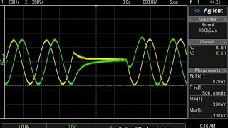
Yellow and green traces look the same to colour blind viewers...
Oh so that's why the traces look the same color to me.
Blue and red would be OK, I believe.
when i saw bipolars, i knew it is junk
This is fantastic content. You are very thorough. Wish you had more of this!