Here's a good practical application: when i was learning the 555 timer in engineering, my professor challenged us to make a traffic light circuit with minimal components. Only the 555 timer was allowed, along with passive components. You can do it with just two 555 timers if some one wants to give it a shot. Awesome video Karen!
I combined 2 of these circuits with variable resistors, activated by one switch to make a twin timer for making perfect boiled eggs and toast. It times the boiled egg and also tells me when to start cooking the toast so that the timing is perfect, once you set the resistors.
Karen's presentation and teaching style makes learning electronics a whole lot easier. Rather than being left baffled with a mash of improperly delivered information like from many lessons on other channels, you deliver the needed info in an concise and understandable way. Love this series! Waiting to see more on The Learning Circuit!
Hi, Karen just to let you know your presentations of the 555 are excellent and I love to show your presentations to my students, clear learning . I also use tinkercad where they explore the circuits and can see simulations and proof when they have difficulty with breadboard connectivity. Love your work . I've been teaching electricity modules for the last 14 years, after a long career of more than 41 years on the railroad as a electrical supervisor and now this ongoing career , it is fun to see young students go out and become electricians and technicians..😎great service you are doing for young aficionados of electronics.
Apparently I accidentally said astable TWICE at the beginning. Sorry about that, folks! Guess I was just having one of those days. This is a MONOstable, one-shot time.
I've watched several videos about the 555, but only after yours I finally understood! Thank you - good job:) I serched for debouncing limit switches, so maybe this can be one of way to use 555:)
great video and lesson. I'm brushing up on 555 after many decades...I'm using 555 timer in one shot mode and feeding it into a 74LS04 hex inverter to create synchronized differential logic pulses and sending into a motion controller as a homing reference pulse. The controller requires differential input but the machine I am retrofitting only has a single ended reference marker pulse. I use this pulse to trigger the 555 timer and hence create the differential signals.
I've used the 555 for quite a few projects. First one was to delay power on of a wind speed and windshear sensor monitor, that I built for my car. I needed the monitoring device to start several seconds after the car has started. In a second project, I used the 555 to build a circuit for strobe lights. Well, I used the 556, dual timer, IC, to drive two LED strobe lights. Even though I've used the 555 before, I can't say I fully understood how it worked...until I watched this video.
You did a fabulous job explaining how it works. Thank you for that. I don't think I have ever used 555 but this time I need a pulse width extender and this is a perfect application of this IC for this purpose. I like to use MOSFETs for all kinds of stuff but this solution is way more simple!
Thanks for the series. The short burst (and timed burst) comes in handy in gaming applications with individuals with cognitive and/or physical disabilities. I have a student who can access several switches, but not a joystick. In first person games like Minecraft, he winds up spinning when he engages the camera mode to look around the world. It's sensory overload. However, by limiting the activation time of the switch regardless of how long he hangs on it he can do what he wants to do. Next, I'm working on seeing if I can just really suppress the speed of the camera movements. What makes it an even more interesting challenge is the switches are also used for walk mode where he doesn't have the spin issue.
One time I made a 555 circuit in mono mode to temporarily turn off a smoke detector while cooking so the smoke would not set it off for about 10 minutes....I wired a tiny switch under the cabinet using thin magnet wire to the trigger input. C=100uF, R= whatever was closest to 5.5 Mohms in my resistor cabinet. The circuit was p-p wired on a small perfboard and fit inside the cover. If I remember correctly I used the CMOS version of the chip for low power drain (7555). Worked great and was safer than pulling the battery out and forgetting to put it back in, and more convenient! Note: Try this at your own risk - I don't want you to violate any fire codes or cause safety issues!
Very very good explanation mam I have understood the working .. but I have seen lots of videos regarding the timer ic 555 I am unable to understood the working but after watching this video I understood the how the one shot timer works .. thank you mam ...Love from India...🇮🇳🇮🇳
Hello Karen, I’m using the 555 to ring a doorbell when a motion sensor detects movement. I wanted to create a normal sounding “ding dong” on the ubiquitous NuTone door bell, even though the motion sensor stays high for many seconds after being tripped. Thanks for the demo. 👏
One application could be frequency division, an incoming clock trigger could be used instead of the button presses. Depending on the values of the capacitor and resistor, which could be arbitrarily selected, the pulse width could be worked out. This would lead to a new frequency, perhaps a division of the clock.
nice video, got a quick question though. Can the timer turn of even when the button is still bein pressed? should be possible right, because the button doesnt mess with the C2 threshhold right?
Thanks for this!! I have a question for you. I have been trying to figure this out for some time now. I have a few claw machines I rent for events. I bypassed the coin mechanism and pulled out the wires and connected them to a credit switch for free play. The problem is if someone holds down the credit switch too long the machine throws an error thinking there is a coin jam. I tried ordering a one shot LM 555 kit to adapt to the switch, hoping I could get a single pulse signal to the machine no matter how long someone presses the button. I hooked everything up and was hoping I would get the result I would like. Problem is I believe that the claw machine credit switch is actually just completing a ground circuit whereas the one shot LM 555 kit is intended to send a voltage pulse. I was wondering if you would think there would be a workaround for this? Thanks for your great videos.
What happens when you hold the button? Will the led still turn off after a time? Basically what I want is to build a circuit that will create a single pulse on the rising edge of a button press that will go down even if the button is held. I believe a 555 timer would be the way to go about it but I don't know if this is the right approach... (I have little electronics experience)
could use as door chime, motion alert, mailbox notifier, sump pump fail alarm, drive way alarm all sorts of uses. the button can be any sort of activating device and the led can be a light or buzzer or relay to trigger something else only limited by what you can think up.
Great video. By coincidence I could have used it today, I had a 10 port powered USB hub I wanted to coorperate in a product. Problem was I had a momentary on/off switch and didn't go on automaticly when supplying power. Once incorporated in the product I couldn't reach the button and when the product was powered off there would be no power going to the USB Hub. I found out that shorting the button with a resistor did the trick but otherwise this would be the solution to simulate the buttonpress
Great lesson Karen...but...what's a practical application for this circuit? /s Great description. I've used and abused 555's many times before but never dug deep into the operation; just blindly followed some diagram. This really helps understand what's going on.
@@arathcazares1326 Not sure if that reply was intended for me or if I missed something...I never mentioned mono or astable... so makes me think you were replying to someone else.
frollard forget what I said because I thought you were confused with practical circuits, by simply use two resistors and a capacitor. Make it as astable, but I also realized that she meant "a stable", not "astable from the video.
An indicator system for an automobile could also be built, with the mechanical pull of the indicator leading to the connection of the 555 timers to the power supply. The R and C could be arbitrarily selected, such that R*C=1s. The output of the 555 timer could be passed through a buzzer and an LED.
Hi Karen. I like your training style. I watched your video "How 555 timers work - The Learning Circuit" and you show Comparator 1 connected to pin 8. In this video you show Comparator 2 connected to pin 8.... I watch a different channel explanation which shows Comparator 1 to pin 8. Which I now assume is the actual correct configuration. Sorry to say.... I am now confused by this video lesson as it now does not make sense, or am I just a stupido?
I would use it to give a regular impulse to a Focault pendulum. Instead of a button, magnet at the bottom of the bob would induce a voltage passed through a capacitor and the output woud momentarily power an electromagnet which would attract the magnet. That is the basic idea. A small PV cell would keep LiPo cell charged, which will power the cisrcuit continuously.
Hello Karen, You made a very nice video, congratulations. I have a question for you; trigger signal How do I make the output be 2ms whether it is 1ms or 10ms. Thank you.
Hi there, Can you design a variable on and variable off timer with 2 pots for each actions, I mean the hi time changes with one pot and the off time with the other pot. I dont mean a timer with one pot to change the duty cycle, but two pots. It can be with 555 or arduino or whatever. Thanks a lot for your patience to teach.
Real world application off the top of my head. Door latch buzzer. Input would be an impulse like a dial tone from a phone system or a user press button. The impulse triggers the 555 which pulls high to buzz the door lock for 5 seconds. And at the button end you could have equally simple circuitry to form a latch to stop a user holding the button to override the one shot.
Thank for awesome information about 555 timer , but my questions about 555 timer is , how can I tests or know when is it bad using multimeter? Thank you for now.
I have a beacon with a 555 2 resistors and 2 capacitors. Im trying to get the led stays on about half second and off about 2 seconds. I've tried and changed some some resistors and capacitors around and i can't get inequality values. Only equal. Which i dont want equal values. I want half ON and 2 second OFF approximately.
Hi! Are you really sure, if you release the button at Pin2 and the VCC reconnected to Pin2 again throug a resistor does not change the output? I build this circuit and after I release the button it switch back to low...
Help me please. You say Astable mode but the graphic says Monostable mode. Am I correct that it is Monostable mode,... not Astable mode?? I thought Astable was blinking output as long as it is triggered. And Monostable it will blink once for an amount of time and than waits for the next triggering...
@ element14 presents would this circuit still work if the trigger is continuously switched since the circuit is powered up? I would like to create a circuit that lights a LED for 5 seconds when VCC is switched on and then keep the LED off until VCC is switched off and back on.
Should there be a (small) resistor between the capacitor and the discharge pin, to limit the amount of current flowing out of the capacitor and through the transistor at the end of the one-shot pulse?
If you wanna make me flip Hit me with a micro chip I'll be a diode, cathode, electrode Overload, generator, oscillator Make a circuit with me - The Polecats


I wish if I knew this series when I was in the university, she could explain electronic topics easily. Good job, thank you
Here's a good practical application: when i was learning the 555 timer in engineering, my professor challenged us to make a traffic light circuit with minimal components. Only the 555 timer was allowed, along with passive components. You can do it with just two 555 timers if some one wants to give it a shot. Awesome video Karen!
I combined 2 of these circuits with variable resistors, activated by one switch to make a twin timer for making perfect boiled eggs and toast. It times the boiled egg and also tells me when to start cooking the toast so that the timing is perfect, once you set the resistors.
Karen's presentation and teaching style makes learning electronics a whole lot easier. Rather than being left baffled with a mash of improperly delivered information like from many lessons on other channels, you deliver the needed info in an concise and understandable way.
Love this series! Waiting to see more on The Learning Circuit!
I love this series, it's easy to learn with this kind of presentation.
Hi, Karen just to let you know your presentations of the 555 are excellent and I love to show your presentations to my students, clear learning . I also use tinkercad where they explore the circuits and can see simulations and proof when they have difficulty with breadboard connectivity. Love your work . I've been teaching electricity modules for the last 14 years, after a long career of more than 41 years on the railroad as a electrical supervisor and now this ongoing career , it is fun to see young students go out and become electricians and technicians..😎great service you are doing for young aficionados of electronics.
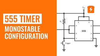
Apparently I accidentally said astable TWICE at the beginning. Sorry about that, folks! Guess I was just having one of those days. This is a MONOstable, one-shot time.
I've watched several videos about the 555, but only after yours I finally understood! Thank you - good job:) I serched for debouncing limit switches, so maybe this can be one of way to use 555:)
great video and lesson. I'm brushing up on 555 after many decades...I'm using 555 timer in one shot mode and feeding it into a 74LS04 hex inverter to create synchronized differential logic pulses and sending into a motion controller as a homing reference pulse. The controller requires differential input but the machine I am retrofitting only has a single ended reference marker pulse. I use this pulse to trigger the 555 timer and hence create the differential signals.
I've used the 555 for quite a few projects. First one was to delay power on of a wind speed and windshear sensor monitor, that I built for my car. I needed the monitoring device to start several seconds after the car has started. In a second project, I used the 555 to build a circuit for strobe lights. Well, I used the 556, dual timer, IC, to drive two LED strobe lights.
Even though I've used the 555 before, I can't say I fully understood how it worked...until I watched this video.
You did a fabulous job explaining how it works. Thank you for that. I don't think I have ever used 555 but this time I need a pulse width extender and this is a perfect application of this IC for this purpose. I like to use MOSFETs for all kinds of stuff but this solution is way more simple!
Thanks for the series. The short burst (and timed burst) comes in handy in gaming applications with individuals with cognitive and/or physical disabilities. I have a student who can access several switches, but not a joystick. In first person games like Minecraft, he winds up spinning when he engages the camera mode to look around the world. It's sensory overload. However, by limiting the activation time of the switch regardless of how long he hangs on it he can do what he wants to do. Next, I'm working on seeing if I can just really suppress the speed of the camera movements. What makes it an even more interesting challenge is the switches are also used for walk mode where he doesn't have the spin issue.
Wow I love to absorb so much knowledge with such ease. Thank you internet and thank you Karen.
I follow you all the time. It gives me a lot of knowledge and I like you the most in the world.
One time I made a 555 circuit in mono mode to temporarily turn off a smoke detector while cooking so the smoke would not set it off for about 10 minutes....I wired a tiny switch under the cabinet using thin magnet wire to the trigger input. C=100uF, R= whatever was closest to 5.5 Mohms in my resistor cabinet. The circuit was p-p wired on a small perfboard and fit inside the cover. If I remember correctly I used the CMOS version of the chip for low power drain (7555). Worked great and was safer than pulling the battery out and forgetting to put it back in, and more convenient! Note: Try this at your own risk - I don't want you to violate any fire codes or cause safety issues!
haha! great thinking right there. I will keep that in mind, but I won't promise anything. great idea, though! :D
Very very good explanation mam I have understood the working .. but I have seen lots of videos regarding the timer ic 555 I am unable to understood the working but after watching this video I understood the how the one shot timer works .. thank you mam ...Love from India...🇮🇳🇮🇳
Hello Karen, I’m using the 555 to ring a doorbell when a motion sensor detects movement. I wanted to create a normal sounding “ding dong” on the ubiquitous NuTone door bell, even though the motion sensor stays high for many seconds after being tripped. Thanks for the demo. 👏
My favorite little IC....use it to build many cool circuits back in the 90s....
Thanks for a really good, easy-to-follow step-by-step explanation.
This is the best explanation. It helped me to finish my project. Thank you.
4:30 Let's connect pin 6 to Vcc through a resistor, not ground.
Very nice and very usable. I am following this series.
I am crying rn, where were you when I was studying for my first exam 😭😭
One application could be frequency division, an incoming clock trigger could be used instead of the button presses. Depending on the values of the capacitor and resistor, which could be arbitrarily selected, the pulse width could be worked out. This would lead to a new frequency, perhaps a division of the clock.
Most excellent video. I haven’t seen “The Learning Channel” for awhile. Are you no longer putting out videos?
Bravoooooooo !!!!!!!!!!!!!!! From Greece with Love
nice video, got a quick question though. Can the timer turn of even when the button is still bein pressed? should be possible right, because the button doesnt mess with the C2 threshhold right?
Great job Karen.
Thanks for this!! I have a question for you. I have been trying to figure this out for some time now. I have a few claw machines I rent for events. I bypassed the coin mechanism and pulled out the wires and connected them to a credit switch for free play. The problem is if someone holds down the credit switch too long the machine throws an error thinking there is a coin jam. I tried ordering a one shot LM 555 kit to adapt to the switch, hoping I could get a single pulse signal to the machine no matter how long someone presses the button. I hooked everything up and was hoping I would get the result I would like. Problem is I believe that the claw machine credit switch is actually just completing a ground circuit whereas the one shot LM 555 kit is intended to send a voltage pulse. I was wondering if you would think there would be a workaround for this? Thanks for your great videos.
What happens when you hold the button? Will the led still turn off after a time? Basically what I want is to build a circuit that will create a single pulse on the rising edge of a button press that will go down even if the button is held. I believe a 555 timer would be the way to go about it but I don't know if this is the right approach... (I have little electronics experience)
most useful vedio in youtube for me .thanks
could use as door chime, motion alert, mailbox notifier, sump pump fail alarm, drive way alarm all sorts of uses. the button can be any sort of activating device and the led can be a light or buzzer or relay to trigger something else only limited by what you can think up.
0:27 "Astable mode also known as a 'One-Shot' timer"
Astable is Free Running
Monostable is One-Shot
(Otherwise) Great graphics and presentation
I was wondering if you could create a video explaining how to use a 555 timer with two MOSFETs to alternate two blinking 3 amp, 40-watt led's. Thanks
Great video. By coincidence I could have used it today, I had a 10 port powered USB hub I wanted to coorperate in a product. Problem was I had a momentary on/off switch and didn't go on automaticly when supplying power. Once incorporated in the product I couldn't reach the button and when the product was powered off there would be no power going to the USB Hub. I found out that shorting the button with a resistor did the trick but otherwise this would be the solution to simulate the buttonpress
Very nice video & explanation, Thanks Madam
Great lesson Karen...but...what's a practical application for this circuit?
/s
Great description. I've used and abused 555's many times before but never dug deep into the operation; just blindly followed some diagram. This really helps understand what's going on.
frollard it's a monostable circuit, not astable. 😂 Which is no stable state, but just a relaxation oscillator.
@@arathcazares1326 Not sure if that reply was intended for me or if I missed something...I never mentioned mono or astable... so makes me think you were replying to someone else.
frollard forget what I said because I thought you were confused with practical circuits, by simply use two resistors and a capacitor. Make it as astable, but I also realized that she meant "a stable", not "astable from the video.
frollard It's not practical, but it's kind of is by involving oscillator.
Hi Karen great job 🤗🤗🤗🤗
An indicator system for an automobile could also be built, with the mechanical pull of the indicator leading to the connection of the 555 timers to the power supply. The R and C could be arbitrarily selected, such that R*C=1s. The output of the 555 timer could be passed through a buzzer and an LED.
Very concise. Thank you.
At the start of the video perhaps you meant to say monostable mode, not "astable mode"? Clarification is in order here. Thanks.
Hi Karen. I like your training style. I watched your video "How 555 timers work - The Learning Circuit" and you show Comparator 1 connected to pin 8. In this video you show Comparator 2 connected to pin 8.... I watch a different channel explanation which shows Comparator 1 to pin 8. Which I now assume is the actual correct configuration. Sorry to say.... I am now confused by this video lesson as it now does not make sense, or am I just a stupido?
I would use it to give a regular impulse to a Focault pendulum. Instead of a button, magnet at the bottom of the bob would induce a voltage passed through a capacitor and the output woud momentarily power an electromagnet which would attract the magnet. That is the basic idea. A small PV cell would keep LiPo cell charged, which will power the cisrcuit continuously.
Thanks for this series and its very usefull stuff i love you mem from India 🇮🇳
Hello Karen,
You made a very nice video, congratulations. I have a question for you; trigger signal
How do I make the output be 2ms whether it is 1ms or 10ms.
Thank you.
What happens if you leave your finger on the button? Does the timer start as well or does it only start if you release the button?
I am using this for my spot welder through variable resister fron .25 sec to about 2.5 seconds.. Switch on MOT through a relay..
Great presentation.
Hi there, Can you design a variable on and variable off timer with 2 pots for each actions, I mean the hi time changes with one pot and the off time with the other pot. I dont mean a timer with one pot to change the duty cycle, but two pots. It can be with 555 or arduino or whatever. Thanks a lot for your patience to teach.
Fantastic, thank you
Real world application off the top of my head. Door latch buzzer. Input would be an impulse like a dial tone from a phone system or a user press button. The impulse triggers the 555 which pulls high to buzz the door lock for 5 seconds. And at the button end you could have equally simple circuitry to form a latch to stop a user holding the button to override the one shot.
what happens if you keep holding the button? Will it turn off? I'm looking for a circuit like that since more than a week
Amazing content!
I'm wondering if you can do something similar with 74 series NOR gate as the sr latch and an OR gate as the comparators?
At the 28 second point of this clip didn't you mean to say monostable mode rather than astable mode?
I wish you were my teacher !
Well done, very clear, thank you.
Thank for awesome information about 555 timer , but my questions about 555 timer is , how can I tests or know when is it bad using multimeter? Thank you for now.
measure the value of the resistance between Pin1 and Pin8. There are 3 5 kOhm resistors. If the result is 15 kOhm, the 555 is mostly fine
I have a beacon with a 555 2 resistors and 2 capacitors. Im trying to get the led stays on about half second and off about 2 seconds. I've tried and changed some some resistors and capacitors around and i can't get inequality values. Only equal. Which i dont want equal values. I want half ON and 2 second OFF approximately.
It's good for debouncing.
So excellent
Thank you very much
great video but what about pins 4 and 5
Can you explain how multivibrator works?
Hi! Are you really sure, if you release the button at Pin2 and the VCC reconnected to Pin2 again throug a resistor does not change the output? I build this circuit and after I release the button it switch back to low...
Thanks, Karen. You're showing me how a Dub Siren works ;)
Help me please. You say Astable mode but the graphic says Monostable mode. Am I correct that it is Monostable mode,... not Astable mode?? I thought Astable was blinking output as long as it is triggered. And Monostable it will blink once for an amount of time and than waits for the next triggering...
Nice video
Thank you
I’m confused. Does this vid describe an a stable or mono stable mode?
6:50 The transistor is on (not open!) connecting the capacitor to ground through the discharge pin.
wt if i hold trigger push button for 5 second , will the timer works or the output stays on.
@ element14 presents would this circuit still work if the trigger is continuously switched since the circuit is powered up? I would like to create a circuit that lights a LED for 5 seconds when VCC is switched on and then keep the LED off until VCC is switched off and back on.
Very informative
Oops, accidentally said astable mode at the beginning ;) but great video!
[facepalm] How did I not notice that?! Lol. Nice catch.
@@maker_karen1785 lol, I call something by the wrong name all the time. It's the most common mistake that I fail to realize I am making while filming.
Very nice.
Thank you.
I also want a 555 timer circuit with a push button, 1/2 second pulse out even push button press long time. Plz, thanx in advnce.
Awesome reliable chip has been around since 1972
What type of flip flop is use in ic555
I'd use this to turn a motor for a specific period of time from a single click of a button. Like starting a trash compactor.
104 capacitor use between 8 and 6 pin for stable work
Should there be a (small) resistor between the capacitor and the discharge pin, to limit the amount of current flowing out of the capacitor and through the transistor at the end of the one-shot pulse?
Nice
Hi Karen I missed you
muito bom
If you wanna make me flip
Hit me with a micro chip
I'll be a diode, cathode, electrode
Overload, generator, oscillator
Make a circuit with me - The Polecats
I used a 555 timer like this to build a circuit board for a paintball gun
Good
One application is to timing in automation circuits
What if push button is continioues ON
2:19 That's an SR Latch, not a Flip-Flop.
Fo real
Mistake at 4:34
Button debouncing !!!
👏👏👍💞👑😘😍🌷🌹
watchdog timer , great video
Is no one going to mention the fact she said astable twice at the beginning, before changing to monostable without comment?
Door buzzer for security doors.🤪
The description is to hard to understand and if its completely right it needs to be dumbed down.
one shot is mono stable not astable
VVV