Reconditioning your car battery (desulfator) Part 2 - The circuit design

ฝัง
- เผยแพร่เมื่อ 6 ก.พ. 2025
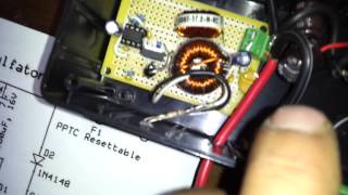
- This is part 2 of my series of videos pertaining to reviving old car batteries. In this video I will show you where I got the schematic for building the desulfator and once again show you my finished desulfator circuit up close.
Here is the part list for newark.com :
IRF9Z34NLPBF - P channel mosfet - 1
MR856RLG - Fast recovery diode - 1
1N4148 - switching diode - 1
MCMF0W4FF3301A50 - 3.3kohm resistor - 1
CMF1/41101FLFTR - 1,1kohm resistor - 1
MCMF0W4FF6802A50 - 68kohm resistor - 1
MCMF0W4FF1004A50 - 1mohm resistor - 1
ELXZ350ELL101MF15D - electrolytic capacitor 100uf - 2
MC0805N102J500A2.54MM - ceramic capacitor 1000pf - 1
MCMLR100V103KX7R - ceramic capacitor 0.01uf - 2
MC0805B473K500A2.54MM - ceramic capacitor 0.047uf - 1
2100HT-102H-RC - inductor 1000uh - 1
PM2120-221K-RC - inductor 220uh - 1
MF-RX110 - ptc reset fuse - 1
DILB8P-223TLF - 8 pin dip socket - 1
SA555PG4 - 555 timer chip - 1
Here is the link to part 1 which is the main overview of the desulfator:
• Reconditioning your ca...
Here is the link to part 3 which shows how to connect the led to the circuit to show you that it is working:
• Reconditioning your ca...
Here is the link to part 4 which shows some basic troubleshooting points on the circuit:
• Reconditioning your ca...


Good luck!! I'm actually getting ready to send out the board design to the fabricator for the production version of the circuit. Hopefully I'll have them tested and ready by april.
I do not build and sell them. I have a video up that will show you how to order the circuit boards and then a parts list that you can use to order the components from newark.com. Look in my playlist for the desulfator series and it should be the last one.
Very informative. Thankyou. My 6 stage battery charger already has a rejunvenation
phase (desulfation) which runs for exactly 24 hours.
Kyle thanks! And no I haven't played with the mains powered variant yet. I should be going back to playing with the desulfator this fall/winter once I'm done designing the "infinity sun jar"
Thanks for the really good videos on I am going to try and build my own. It,s a simple enough schematic for me to etch my first board.
I didn't forget about you mag7mm1, hopefully i'll get a chance this weekend to open up one of my desulfators and look at the circuit board and let you know where to put the led at.
791bigdaddy - I have the parts listed in the description of this video. You purchase them at Newark.com
Could you show how you connected the led? If you could make a step by step video on how you built it. Thanks for the video Im building one myself and this helps alot.
Cyberdems - I have a seperate video for the dc-dc converter, but it's purpose is a trickle charger to replenish the power used by the desulfator. It is not essential, but makes life easier. I don't have a kit form as of right now, but once I'm done with the "infinity sun jar" project I plan on revisiting the desulfator and designing a true PCB for the circuit.
Really helpful video thanks! Will you please make a step by step video on how you built your 6 Amp DC-DC converter and also how you connected it to the original circuit from the schematic?
Just wanna say thanks for the video. Finally, have mine working without the dc-dc converter. Now I'd like to step it up a notch and include the dc-dc converter too but not sure how. Did build your own dc-dc converter, or did you buy a trickle charger that you opened up and somewhow connected to the desulfator?
Mag7 - what is the voltage of the battery that the multimeter shows before you connect the desulfator?
Thank you for the video. I am plannig to build this as it can solve my battery problem.
one thing I cannot understnd is 3.3 K resistor which devide the negative line. 555 ic cannot deliver much current and that resistor would not pass an adequate current to the battery it seems. Even for high frequency it need an amount of current to work on the lead plates with sulpate. Is it not necessary to have particular amount of voltage and current to act on sulphate? Thank you.
It does have some effect on the timing, if you substitute it with an incorrect value you could end up having the mosfet on of off at the wrong percentage. This will either burn up the mosfet or render the desulfator useless.
Was wondering if you might know whats wrong, completed and connected to battery, the unit makes a quiet noise but when I check the voltage at the diode and buy the torrits it is really low like .6volts? I dont believe its building up the higher voltage.
Thanks
Sorry if you couldn't understand how to build one of these units but my videos are meant for someone who has some basic electronics experience such as reading a schematic.
When you have you trickle charger connected to the desulfator in parallel to the battery. What did you use to stop the higher voltage from back feeding into the charter unit?
driftboatlou - the schematic is not mine, it's frontier springs. I mentioned in one of the videos that the schematic is wrong when it came to the mosfet for that very reason. When I'm done doing my series on my "Infinity Sun Jars" I'm planning on coming back to this and drawing up a proper schematic. Might also decide to start making the PCB's for this since frontier springs seems to have fallen off the face of the earth.
Hi there. I am very impressed with the schematic but I don't think that I can build one myself. Is there any way that I can buy the desulfator? Do you build and sell them. Thank you in advance for your response.
Actually the 555 timer works perfectly for this application and most people (myself included) don't know any programming regardless of PIC or arduino.
I get that D1 is the damping diode avoiding going negative. But why the double coils and why C4 between the main coil and positive? The voltage over C4 should be way more than 16V.
D2 C6 look counter productive in removing the high frequencies produced by the rise of the pulse.
Hey so I put together the desulfator circuit (without the dc-dc converter) on a breadboard to make sure I have everything right before I start soldering and for some reason my fuse is getting real hot when I hook up the circuit to the battery. Any tips on how to fix this? Maybe I'm connecting the mosfet wrong? I have the gate connected to the 555 chip side, the drain connected to the inductors and diode, and the source connected to the positive line.
very good job...congratulations !!! can this desulfator run in parallel with the battery charger???
Thats why you use a desulfateor with a battery charger. I would suggest you use a driver transistor for the mosfet
rrfox100 - sorry it took so long to respond, post wedding day cleanup is still going on and finishing my wife's move-in with me. r3 drops the voltage from 12 volts to around 6 volts to safely power the 555 circuit so your observations are correct. :-)
Yes it can run parrallel with a trickle charger. That's how I use them on my batteries.
your videos are full of nice informations. i love homemade sincere tutorial like that ! (i made a few on rather different topics...) What about using EPSOM SALT ( magnesium sulfate ) ?
Question about Q1 IRF9Z34 hookup. Half the circuits (like yours) show the S leg connect to L1 and D connected to Positive voltage. The other half (like TH-cam SLA battery plate desulfator) shows just the reverse, the S leg connected to the Positive voltage and the D leg connected to L1. Please help my confusion, thanks
Does capacitor 2 determine the timing on the 555 chip? I've only got .022uf, .01uf or .047uf to use and was wondering if I could substitute if its just there to smooth out voltage?
Thanks for the nice vid and diagramm !!!
Is there one that works I can just buy?
I don't know how it looks questionable as I have shown proof that the circuit works in my videos. And as for being designed by a professional electronics engineer, please refer to home power magazine issue #88. It was designed by a person who submitted it and now has a loyal foloowing of people who see that the circuit really does work. And I am by no means a professional electronics engineer, just your averge everyday truck driver that plays with electronics on the side.
Y using 2 inductors. Can we use only one to return voltage spike
Have you put this on a oscilloscope?. I built the same circuit and it did not put out enough voltage
What about DC to DC converter ? Where did you get it or how can you build one ? You seemed to have forgotten to xplain this part.
I have looked online for a schematic but most are not explained very well and would NOt be suitable for this app.
Most likely you put the mosfet in backwards. I've done that a few times myself. Flip the mosfet around on your breadboard and you should be good.
the L2 inductor is not available from jameco, they have one with a little different spes. the one they have specs are 1000uh 1.3 IDC .4 ohm. do think this would be a problem
I have a 4 ///12-volt battery how many hours can you leave the desulfator face hooked up on for batteries that is a solar Bank
That would be awesome - thanks!
Just got that same cen-tech multimeter from amazon yesterday :-)
Hi, Very Informative, i wanna ask that can i connect the desulfator circuit parrallel to battery while its Charging by my UPS?
Yes u can
nice vid, thank you for the info sr
Just to let people know, that schematic has the mosfet in bacwards, so if you built it and wonder why it does not work, try switching that. Hope this helps someone.
1] Hi, I was wondering if bigger is better in desulfating a battery. I want a heavy duty desulfator that will blast off the sulfate quickly. I figure if you used a triple strong pulse every so often, "timed in between pulses," that might be like hitting the sulfate film with a stick, and start to loosen the sulfate back in to solution.
2] I was also wondering if dumping out the acid and replacing it with a baking soda solution will draw off the sulfate much faster. I figure baking soda is a base and sulfuric acid is, well, an acid. I have heard this will quickly dissolve sulfide back into solution. You can rinse out the battery and reuse your acid.
Please let me know what you think. I think this might speed up the process and revive doomed battery's.
Please note that I have not tried this myself, but I thought you might like to try it.
Please be careful, wear a splash shield incase of explosion, just in case.
pateince is key young padawon.
11.75 volts I also had the charger connected with the desulfator.
Your current is too high, should only be around 100ma max. 1.2khz is okay, that wouldn't be causing it to heat up. I would check your solder connections as it sounds like the mosfet is not being turned on/off HARD, or the mosfet is faulty or you subsituted the mosfet for a different model. Other then that I have no clue.
Hello sir, I am from Bangladesh Asia, please you can you send schematic for 12 volt Battery.
Let me see if I can make you up a video this weekend.
hello dear sir
plz tell me the frequency it generates ?????????
ive read that home power magazine issue #88 article. since ive seen several other of those devices.. this looks by far strange and uncommon. questionable since ive seen several "hacked together" devices that "somehow" work in "some way" but those who did it often dont realy know what they did there. there are schematics around that "make sense" the way they look. but im troubeling with this one. it could be just me, but im dont think this is a prober schematic.
Not trying to be a wise ass or anything! Epson salt recondition seems to work fine and battery chem has something better. Your de-sulfater is way cool & tec but I don’t have the smarts to make one. Can a good one be purchased & if so where?
Look for products from CTEK (MXS 7.0). This gadget should be able to desulfate batteries.
If the battery reads below 10volt one cannot revive the battery with desulfator.
jagadeesh patil Not entirely true. I have revived batteries there were sitting at 9V for a 12V battery. I do concede that your rate of success goes down as the battery has been sitting dormant for longer periods of time.
+jagadeesh patil Not certain about the points made but ,if anyone else wants to uncover how to recondition batteries try Renkarter Rapid Renew Report (do a google search ) ? Ive heard some amazing things about it and my buddy got amazing results with it.
+jagadeesh patil hi everyone ,if anyone else wants to uncover how to recondition old car batteries try Vaxicorn Battery Extender Guide (do a google search ) ? Ive heard some decent things about it and my m8 got amazing success with it.
+jagadeesh patil
Wrong. I've revived 12V starter batteries as low as 5.5V
It all depends on how the batt was discharged & for how long the sulfation crystials have bonded.
+jagadeesh patil There are several factors in battery reconditioning. One resource I discovered that successfully combines these is the Magic Mender Wizard (check it out on google) definately the best info that I've heard of. look at this awesome site.
Putting anything in a battery besides distilled water will distrupt the delicate balance of the electrolyte and destroy your battery.
You also didn't explain how it was connected with the desulphator
Glad you got it working! Go to my channel and look for the video for float charger, that details the dc-dc converter.
Hello, I am terrible at reading schematics and assembling them, I was curious if you wanted to build on of these for me. Send me a message please.
I was lazy to build my own and bought this www.amazon.com/gp/product/B000P23HZS/ref=oh_details_o00_s00_i00?ie=UTF8&psc=1 but I tested the frequency across the terminals of the battery while the unit was connected and I did not get a Hz reading. I was wondering if you test your battery while your desulfator is attached, would you get a frequency reading? I'm guessing you should get the frequency that the MOSFET turns on and off?
Let me know how the batteryMinder works for you
You can buy them real cheap on ebay. Around $8 shipped, can't make it cheaper, really, IMHO
mag7 - check my channel as I just uploaded a video that will help you start troubleshooting your circuit. I've built 3 of these so far and each one i have overlooked something simple, such as a diode in the wrong direction or the mosfet flipped around.
Unfortunately all I can show you is a before and after as desulfating a battery is not a fast transition in a battery. You requiring me to show a dead battery suddenly brought back to life in the same video take is absurd. I couldn't even show you a discharged and charged battery in a single take unless you want to watch 8-16 hours worth of straight unedited footage. Sorry you feel as though im tricking you but that is not my intention with my videos, only passing on knowledge.
no you havent, you have shown us "before and after" you have never shown us a battery with a resistor pack showing low voltage, then connected to a desulfator and subsequently charged and then put on the same resistor pack showing a higher voltage, in a single take. that would be proof.
if i was to produce the product i would steer away from the using a 555 timer. PICs are way more efficient.
The whole schematic looks "questionable" to me. strange build. i doubt this is made by a professional electronics engineer.
if you cant read a schematic i suggest you stay away from electricity my friend dc amps kill its not your basic 120v ac that tickles your gutty wuts
Avoid desufators period. Backward technology.