The good video! With the simplest RF mixer (common base one BJT mixer) and one IF stage with a BJT the CD4046 can receive FM stations! The main essential thing - how to stabilizing feedback loop had not been covered. The resistor 4.7K in series with the 100nF capacitor and an another small (4.7nF) capacitor connected between pin 9 and the ground maybe solved this problem.It decreases shapeshift and reduces Bode plot falling rate to 20dB/Decade.
Your channel is the best thing ever had in the TH-cam. The reason you can you demodulate with phase is because you assume baseband is practically much smaller than carrier frequency. Is that true?
Pretty sure the phase comparator with 1k resistor isn’t causing oscillation / instability, the wave you can see is just the noise from the 10kHz fgen. The frequency of the square wave at the output of the XOR phase detector will be twice that of the VCO, so filtering it you’ll get some ripple, in this instance at 20kHz. The corner frequency of the filter is only 1.5kHz with this faster filter after all. A synchronous peak follower can sit on the output of the phase comparator’s filter and get better ripple rejection than a high-frequency filter alone, and faster response rate than a low frequency alone. A multipole filter may be a simpler method though.
I do agree that my signal generator is quite noisy, so that may be an issue; But even though the corner frequency of the LPF is 1.5KHz, that is not necessarily the crossover of the loop. in the first measurement (R=100k, C=100n) the corner frequency was 15Hz yet the oscillation observed was at ~500Hz. I guess I will analyze the subject of loop response and stability in more detail in another video and try to properly measure it.
In older radios you had a mechanical variable capacitor while in the newer ones you get varicaps; regardless, the variable capacitor has 2 capacitors that turn at the same time, so as you use one of the capacitors for the reception filter, the other is used for the LO. Based on how the coils are designed, the 2 capacitors, form 2 oscillators that have a constant frequency difference.
Hello, On FM receiver, it's common to use the relative "DC" component of the demodulated signal to "adjust" within a certain limit the local oscillator frequency. This is what we call the AFC circuit (Automatic Frequency Control) that allows tracking the HF signal to maintain as constant as possible the central frequency of the IF signal. Monitoring that AFC signal (with a small galvanometer or modern comparators followed by +/- LED) give you an idea on how well the receiver is tuned.
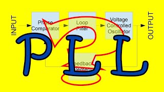
For the phase lock loop diagram make the Low Pass Filter your right most block, going to an output node. Bring the signal back through the Voltage Controlled Oscillator to the input of the Phase Detector. Rather than explaining "the real signal" make it explicit in your diagram that what you want is the output of the LPF and that the VCO is conditioning the feedback to the Phase Detector.
Around what frequencies does the FM signal have to be at to get decent results from the demodulation? I am going to detect a signal at 55kHz (+- 15khz) and I am deciding if I should amplify this
Hi love your videos. Can make a video on isolated DC-DC convert, mainly implementation of push pull, full bridge and Dual active bridge in LT spices would be very grateful.
Not necessarily; From what I remember, one mode of operation relies on measuring the variation of the inductance of a coil; and the other main mode relies on generating electromagnetic pulses, and listening for the pulses bouncing back from metallic objects.
Is this the article you are referring to? www.geotech1.com/pages/metdet/projects/clarke/clarke1_300.pdf Here only the VCO part is used, so you don't really have a PLL (there is no loop). The only reason to use the VCO is to turn a DC voltage into an audible signal; you could replace the VCO with a simple needle indicator.


Thanks for this video. All your videos have so much they need to be seen multiple times to unpack.
The good video! With the simplest RF mixer (common base one BJT mixer) and one IF stage with a BJT the CD4046 can receive FM stations! The main essential thing - how to stabilizing feedback loop had not been covered. The resistor 4.7K in series with the 100nF capacitor and an another small (4.7nF) capacitor connected between pin 9 and the ground maybe solved this problem.It decreases shapeshift and reduces Bode plot falling rate to 20dB/Decade.
I know its too late but continue making these videos please
Thanks you...!! Your method to explain is exemplary...
Your channel is the best thing ever had in the TH-cam. The reason you can you demodulate with phase is because you assume baseband is practically much smaller than carrier frequency. Is that true?
Pretty sure the phase comparator with 1k resistor isn’t causing oscillation / instability, the wave you can see is just the noise from the 10kHz fgen. The frequency of the square wave at the output of the XOR phase detector will be twice that of the VCO, so filtering it you’ll get some ripple, in this instance at 20kHz. The corner frequency of the filter is only 1.5kHz with this faster filter after all.
A synchronous peak follower can sit on the output of the phase comparator’s filter and get better ripple rejection than a high-frequency filter alone, and faster response rate than a low frequency alone. A multipole filter may be a simpler method though.
This comment call for a part 2 ? (It is so well explained, we will enjoy looking at the reaction)
I do agree that my signal generator is quite noisy, so that may be an issue; But even though the corner frequency of the LPF is 1.5KHz, that is not necessarily the crossover of the loop. in the first measurement (R=100k, C=100n) the corner frequency was 15Hz yet the oscillation observed was at ~500Hz.
I guess I will analyze the subject of loop response and stability in more detail in another video and try to properly measure it.
Man I scoured your channel for a video on pll's before my analogue Comms exams 2 weeks ago.
Meh. Better late than never. Let's goooo!
What are the next few exams about? :D
@@FesZElectronics well, whatever is on TV now :))
We finished about 2 weeks ago.
We'll be doing antenna design next semester tho👀👀😏
Thanks for this video.
Lovely video. But I am not able able to get how to synchronise Local oscillator with received modulating signal so that you always get a constant IF.
In older radios you had a mechanical variable capacitor while in the newer ones you get varicaps; regardless, the variable capacitor has 2 capacitors that turn at the same time, so as you use one of the capacitors for the reception filter, the other is used for the LO. Based on how the coils are designed, the 2 capacitors, form 2 oscillators that have a constant frequency difference.
Hello,
On FM receiver, it's common to use the relative "DC" component of the demodulated signal to "adjust" within a certain limit the local oscillator frequency. This is what we call the AFC circuit (Automatic Frequency Control) that allows tracking the HF signal to maintain as constant as possible the central frequency of the IF signal. Monitoring that AFC signal (with a small galvanometer or modern comparators followed by +/- LED) give you an idea on how well the receiver is tuned.
Any tool for simulating the circuit and check ? (Spice model)
Using CD4046
How can you syncronize your scope with a FM modulated RF signal? I´m working with a 40MHz RC transmiter.
Great presentation. But can I use a PLL to demodulate HF signals like 20 Mhz WSPR ?
Can the modulator work without mixing the FM signal with the LO. Why?/Why not?
For the phase lock loop diagram make the Low Pass Filter your right most block, going to an output node. Bring the signal back through the Voltage Controlled Oscillator to the input of the Phase Detector. Rather than explaining "the real signal" make it explicit in your diagram that what you want is the output of the LPF and that the VCO is conditioning the feedback to the Phase Detector.
Me again. Can I replace a Tayloe Detector with a PLL ?
Around what frequencies does the FM signal have to be at to get decent results from the demodulation? I am going to detect a signal at 55kHz (+- 15khz) and I am deciding if I should amplify this
good video
FM receiver DOED NOT respond to changes in AMPLITUDE of the FM signal received !
Hi love your videos. Can make a video on isolated DC-DC convert, mainly implementation of push pull, full bridge and Dual active bridge in LT spices would be very grateful.
How does a metal detector work? They use PLL right?
Not necessarily; From what I remember, one mode of operation relies on measuring the variation of the inductance of a coil; and the other main mode relies on generating electromagnetic pulses, and listening for the pulses bouncing back from metallic objects.
@@FesZElectronics I have a geotech magazine article titled "build an induction balance metal detector" which uses a 4046. I thought all have it.
Is this the article you are referring to? www.geotech1.com/pages/metdet/projects/clarke/clarke1_300.pdf
Here only the VCO part is used, so you don't really have a PLL (there is no loop). The only reason to use the VCO is to turn a DC voltage into an audible signal; you could replace the VCO with a simple needle indicator.
@@FesZElectronics That's the one.
I don't know anything about metal detectors and assumed they all use a pll. Thanks for clarification.
thanks buddy
me:
Next video: How does an phase detector work
nice!