Push on off latching circuit using a push button switch | 555 timer projects

ฝัง
- เผยแพร่เมื่อ 3 พ.ค. 2017
- A tutorial on how to make a Push on Push off latching circuit using a single momentary Push button switch. An explanation on how the circuit works is also included. This Push on off latching circuit is a variant of T Flip Flop realised using a 555 timer IC.
For circuit diagram plus more Info, visit:
* Adding the article right now. Will update the links once it's done*
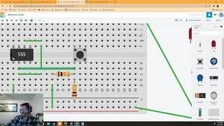
Components Required:
* 555 Timer IC
* 1 tactile/push button switch
* Resistors: 270R, 2 x 10K, 100K
* Breadboard
* Power Supply: (5-12)V
* Few Breadboard connectors
Note: For supply voltage of more than 9V, use 1K resistor for LED instead of 270R
For more electronics projects, visit: elonics.org/
Like our Facebook page: elonics/
Follow on google plus: plus.google.com/+Elonics - วิทยาศาสตร์และเทคโนโลยี


This circuit is PERFECT for my project. I looked at several different latching circuits made of discrete components, but if you press the button steadily, the circuit self-toggles based on the RC time constant. This circuit lets you hold the button forever without changing states. I didn't have to change any component values, worked first time. PERFECT! The 555 is 50 years old but is still very useful, and has a high current output (200 mA) compared to digital chips. TYVM for sharing this.
How much current does this circuit consume when the load is turned off?
Honestly I was about to use an expensive arduino to do a simple pull up button but thank God you made this video! So damn simple and much much cheaper to do for refurbishing a lamp. This does exactly what I needed it to do. Thank you sir!
Still works and still one of the simplest and best designs and explainations of the 555 toggle latch on YT.
This is all I've been searching for. A Simple on/off of one light witha single momentary switch. Thank you!
Thanks you so much for the great explanation about this device. Verrrry helpful.
Excellent video, very helpful and great explanation.
Well done and thanks!
One of the clearest explanations I have ever heard and understood!😃
Thank you very much. The explanation is excellent and really helpful for learners - I think it is a great plus compared to tutorials that only teach how to assemble the circuit without explanation. Keep up the good work.
You're welcome trickybilly. Yes, that's the main motto this channel is based on. Sure
Great explanation of this circuit.
Thank you,
John
Expkanationn 10
FANTASTIC!!!!!
This is the best explanation for the pin 2 Trigger, and pin 6 threshold, that i never see!!!!
Congratulatios!!!!
This cicuit is called....
Flip Flop type
Toggle!!!
You're welcome. Yes, this is a type of flip-flop toggle
Best video on latching circuits. Thank you so much. Every video should be this good. Liked and subscribed.
Best lecture I have ever watched. Thank you.
Thanks! I've been trying to make something like this, but wasn't able to. So when I finally understood how this works, I was quite impressed with it!
Likeddddd it so much .... Great explaination !!!
Amazing! Great teaching!
This is such a great turorial, everything is easy to follow and understand. Keep up the good work!
Very nice mate thanks from France !
Thank you for explaining this...
Wow! Thanks you, this is perfect!!!
Nice! Great job explaining how it works, and a simple to follow tutorial. Very well done. Thank you
Fabulous video! Thank you!
Now I wonder if the button could be substituted for a transistor which opens via a pulse to the base?
The most informative video about how pushbutton on/off circuits work.
I'm not sure this is how they work in a PC, but this is the closest explanation I can find so I will share this.
I want to sincerely thank you for these tutorial videos. I find them very useful. My brother and I are working on a project for his gaming board (RP game), and I am providing the "animation" (lights, sounds, and movements) to add realism/excitement to the game... Your videos provide me with a good understanding of how electronics works (I'm a bit of an electronics novice/hobbyist), and this allows me to use variations of what you have presented. Again thanks for your presentations.
It's my pleasure ronc1357. I'm glad that the video's are helpful.
The project you are working on seems great! I'll be happy to see the arrangement once it's done (please share a picture if possible).
Absolutely! I'm just waiting on components I ordered at the moment, but should be able to start on it in a week or so.
I have a question... I intend to use this circuit in my project, but I wanted to use an IR transistor, instead of a normal push button switch, and use an IR LED to operate it. Is there anything I need to know, or can the IR transistor just replace the switch (in the correct polarity of course)? The power supply will be 12 volts DC.
You are amazing. There were a few moments where the. Camera was moving a little too much, but i love your choice of showing us the circuit with the camera not in a fixed place. It is so much easier for me to see the circuit. Your explanations were good also.
Thanks for the feedback :)
Excellent teaching ... excellent!! Make more videos like this...very good!
Very well presented and explained. Your graphics are excellent.
Thank you for this excellent tutorial, your made this circuit so simple and easy to understand, that it worked on the very first attempt, keep up this good work and god bless you !!!
Fantastic. Thank you.
Thanks.....i was stuck on how this circuit works for days.
Thanks a lot
HE IS LITERALLY AMAZING
AAAAAA AAAAAA
OMG AAAAA
Very very well explained, thumb up.
Great tutorial. Can you provide a schematic where 2 LEDs go on and off opposite of each other? Thanks.
Will this temporary switch have bounce issues? Or is the charging of the capacitor creating the debounce?
Enjoyed the video very much. Great explanation. Can you do a video with same circuit but 3-4 led s
Excellent explanation I did it using 6 volts and works well
Excellent presentation
Is there any way to increase the resistance of the two 10k resistors, to reduce the standby current draw of the switch? I tried 100k and 50k resistors, but it didn't work properly. How might I reduce that standby current draw of the circuit?
Thanks!
-Nick
is it possible to connect a capacitor to the discharge pin to use it in the monostable mode so the output goes low either the cap being discharged or pushing the button the second time?
Thanks and appreciate your thanks for sharing this video. You may also share the map of this circuit on pcb.
wery nice y am planing to use this cirkut on my power suply as an standby mode
it is really nice. how was the circuit extended? I really did not get it clear there.
Thank you so much
Can we use this circuit for servomotor to rotate back and forth??
Imagine you want to build a circuit with 4 push buttons for with different conditions , do we have to use 555timer separately for each push button or can we use one common 555 timer? please help
hello can we add timer on this circuit . please answer thank you
nice vid and description
great circuit, but i need a single switch that when pressed once, it starts a timing circuit, and when pressed again, it will stop the timing circuit and turn off the load. so 2 possible outcomes, one turns off in 15 seconds, OR, press the same switch and it stops immediately. any suggestions?
Man finally a latch circuit that looks promising. However, I turned up the capacitance up to 10uf because it would randomly not shut off during my spice testing. Could be the timing I have set but it would discharge too quickly for the 555 to do anything with the 5v. Again it could be the spice program.
I have been searching for a circuit like this for a long time. Thank you. Pity that you are not more explicit about the two extra transistors added to the output . I guess that one is PNP and the other NPN?
This circuit works. It would benefit from a second 555 to debounce the button but since all my components are soldered to a 555 it would be even messier. Wiuld love to share a photo.
Hi, yes, one is PNP and the other NPN. If you planned to use transistors for toggling between two LED's, there is a much simpler way to so that: th-cam.com/video/TTQnhIkw4Bk/w-d-xo.html
Adjusting the value of capacitor will change the amount of debounce. If the value of resistor or capacitor is more, it take more time for the 555 to accept the next input (ON/OFF).
I shall be happy to see a photo of the circuit you've built. You may upload it here: imgur.com/upload and share the link :)
can i use a mydaq power source for this?
nice making of video
if i use 12v supply and using optocoupler and 12v/5v relay, what the resistor from the optocoupler to the negative rail should be ?, and can you make the diagram please, thank you
good work
Why the values of 10K resistors and a 100K resistor chosen as such?? I've ran this circuit in simulation and have had it function just fine with 2x 5K resistors and an 8K resistor, or a 12K resistor in place of the 100K. Are the values meaningful? Are they arbitrary? Is 10K resistance required to protect the 555 timer? Please advise if possible. Thanks!
How would You get value of that resistor and capacitor
What happens if I can not find a 1uF capacitor and only have a 10uF one? Will this still work or do I need another solution?
coOL.....nice presentation.
Dear sir. Super explanation. Can we provide a input source of 24vdc to this in such case Will it works. And to work on 24vdc input what change need to do. Please advice me. Thanks
Can we use this circuit for powering up Arduino
Hello sir. Where can I get the electronic components for all of your tutorials? I want to follow along, but I do not know which components should I buy.
plz make this type of videos it is very useful .
Definitely
Great explanation..if you explain the circuits of your all videos..that's higher the quality of videos..make more useful videos my best wishes for you
That's a great video...I was thinking to use it for relay on off... I just put my relay in place of led... but there is a problem..
The very first time when I switch on this circuit the relay turns on. Any clue on not to turn on relay on the very first timem
I used a small relay (maybe 1 amp) WITH the LED without any issues.
Hi I want to attach many LEDs, and it is not working. Do I have to adjust the resistors?
Does anyone know if this is also possible with a 556 timer ?
muchas gracias de peru
where can i find
the circuit diagram and link for this project??
Can we use 6 pin push button instead of 4 pin and ground the middle two pins??
Legend
How can I do this but have it turned on by a voltage pulse and no switch. I can find a way to reset it when I want it to stop flashing
Question, if I want to utilize a 12v relay, can I just get rid of the voltage devider and run pin 6 of the 555 timer directly to the momentary switch?
tried it and it doesnt work. Maybe smaller value resistors?
how many time its ruing after one time push?
hi guy. can you tell me why do you use Resistor 10k and 100k? when i use resistor 4k7, my circuit run. but when i turn on power the led ON while my button switch off? when i press the switch, led OFF and i press, led ON.
I WANT WHEN TURN ON MY POWER, LED OFF and led on when i press the switch. thank you so much
@Unique Action can you please provide me with link
thenk you dost
You said it constantly consumes power. What might be the advantage over say a micro processor board that toggles on input?
Low cost and it doesn't require any programming/flashing.
Could this replace an existing on off toggle switch in an existing circuit? (I have an RC remote control that uses an on/off slide type switch but I want to turn it on and off with a momentary button like this)
Yes. But this circuit consumes a continuous current of around 5mA even when idle. So replace only if that current consumption is okay.
Nice tutorial, sadly still missing on web site...
is there no specific button for this?? do i really need to make this circuit??
How to make delay in on and off ike bluetooth speaker power switch ?
I want a pwm circuit to on and off a motor using tactile switch. Can you please help me
Sir I Need The Only On Switch Only how To Disable Off Mode Only On Switched Only
How can we add a functionality ...switched ON...turn OFF after say 25 minutesAlso how much is the power consumption
How much current can handle this project?
I am looking for a switch/circuit which closes just for a second (while staying pushed means closed) and opens up after this on its own. Is there anything like this out there?
Sound like you want a push to break. You could look into an inverter ic.
If the capacitor cant get charged fully via R1 10k how it can charge fully via 100k resistor ??
Could this work just the same if the supply voltage was 3v?
Agnon Wolf not sure, check the 555 specs that'll tell you :-)
does someone know a 12V version of this
Shit dude, that works! Thanks
Does the 555 works if battery voltage 3.7V? In datasheet it mentions 4.5V minimum!?
There are low power variants of 555 that are designed to work even at ~3V (www.st.com/en/clocks-and-timers/ts555.html). Not sure if traditional 555 which requires a minimum 4.5V will work properly at 3.7V.
Many thanks my friend, that's useful
Sir.. Currently I don't have 1uF Capacitor ... So what can I do...? Plzz help
If we push the switch twice then only the output must turn on and the same process to turn off.
Can anybody suggest the circuit?
Sir does it work with tsop1738 ...I mean that if I connect tsop1738 then it will work or not like same on and off ... please sir reply
Sir please reply AS soon ...AS POSSIBLE
Sir,
I make circuit but 9V Power is ON and LED is OFF in this circuit.
Can i Every time 9V power switch ON And LED is ON( not Off) in circuit
How to do ?
Pls reply.........
Really impresive what a explaination style.. great sir.. best of luck for future and god bless you that you teach us more and more. Thank you. Sir if we need any consultation how can we contact you?
You're welcome. You may contact us from here: th-cam.com/channels/DU4GtmCwu3WomTtb0NY6qQ.htmlabout
Sir is circiut me problem ho rhi hai.. ye on easily ho jata hai pr off nhi hota
@@RS-nf1bh After turning ON the output, the circuit freezes for some time to prevent switch debouncing. You can reduce this time by using a smaller capacitor or a smaller series resistor to the capacitor
Elonics - Electronics Projects on Breadboard thankyou sir its working now ok.. sir mai chahta hun ki jb circiut on honto GREEN led on ho jb off ho to RED led on ho ye kaise ho sakta hai kya mujhko daigram banakr mail kr sakte ho.
@@RS-nf1bh Go through this vid: th-cam.com/video/TTQnhIkw4Bk/w-d-xo.html
Can this circuit be used for more than one switch/light (16) or do I need one circuit for each switch/light?
If you need to control all the lights at once, one circuit is sufficient. And if the total current consumed by all the lights combined is more than 50mA, you need to use a relay / mosfet at the output of 555 timer IC.
@@elonics What I mean is 16 individual switches. And one of these circuits to change the behavior of all the switches. Or would I have to build the circuit for each switch.
it will actually be triggering something else, not turn on a led. a grid of keyboard keys, and one circuit to make them all latch.
In that case a single circuit is sufficient to control the behavior of all 16 Individual switches at one go.
Using 12v and a realy in place of the LED and resistor. Relay energizes as soon as power is applied and stays on. Push the button and it goes off but right back on again when you release the button.
Another post suggested a 0.1 uf cap from pin 5 to ground. This solved my problem.
Can someone please tell me what value resistor to use if I want to increase the voltage to 13.8 for automotive use? Thanks!
www.kitronik.co.uk/blog/led-resistor-value-calculator/
Does this draw current when off? If so, how much? Is there a way to make it draw 0?
Without any components, NE/LM555 and LMC555 will draw around 3mA and 0.25mA of current respectively. Additionally the 2*10K resistors connected to Pins 2&6 consume ( (Supply Voltage)/(10K + 10K) which typically equals to 0.2mA ) of current.
So you can achieve the least current draw (~0.3mA) by using LMC555 and by increasing the values of 10K resistors (upto 100K)
Can you provide the explanation for the circuit with addition of the transistors?
I connected the output of 555 timer to the bases of two transistors (npn and pnp).
The emitter pnp is connected to +ve and that of npn to -ve. One LED at each collector pin of npn and pnp.
When the output of 555 timer is positive, it turns on nPn transistor and if negative, it turns on pNp transistor.
can i know what transistor you used?
547 and 557. Dear
The poster of this video did not list the capacitor in the description...
he said 1 microfarad capacitor