Don’t forget that it can take a considerable amount of current to charge and discharge the Gate capacitances in rapid switching applications. Failure to switch the gate quickly enough can leave the device in the dissipation region for longer than necessary resulting in energy losses and heating of the device. It is not uncommon to use a bipolar push-pull circuit or dedicated MOSFET gate driver in high frequency applications.
' Failure to switch the gate quickly enough can leave the device in the dissipation region ' And in the effort to do this part, it's also fairly easy to overdrive or couple something into the gate, and blow out the MOSFET by exceeding the gate voltage. Also, so easy to blow them out from just sitting around with static from air currents and/or mishandling. A lot of manufacturing people do not treat them as being as sensitive as they really are. They can be damaged and then fail 6 months or a year later more often than they should, and it's difficult to attribute that back to the initial cause. Always keep all leads connected until it's in circuit, and have the other parts of the circuit installed before you put them in. Nothing's as fun as having to replace new MOSFETs because you didn't have the gate and reference installed, and blew the gate just handling the board. Cheap good practice was to put in a couple of low value shorting resistors or jumpers to short them out, and only cut them back out of circuit after the board was complete and ready for test. Note even in the video you installed it first not last, literally everyone does that until they finally figure out that isn't the correct method. Even here in the South where it's humid most of the time, it's still easy enough to get 30+V of static charge which is nothing, and then be touching a lead when you're installing the gate drive and whoops you're damaging the gate. Not that big of a deal for one offs and testing, just get another FET when and if it fails. But if you're manufacturing hundreds or thousands of something and you want them to almost all work reliably and not fail, handling practices are critically important. If you can't guess already I was a test and repair and troubleshooting technician in a manufacturing environment, using lots of IRF310's and similar devices back in the 1980's and 90's range. Even in that kind of environment, it's easy to not take it that seriously. But when you finally figure out to do so, it's amazing how many of the 'mysterious failures for no real reason' go away. Just a little info from someone who did some of this, since most hobbyists won't hit the 100 and 1000 unit scale to see to be this 'anal' about MOSFETs and similar. It matters, even if you don't notice it as easily at smaller scale.
@@ModelLights most of my experience is with high current MOSFETs the gate capacitance is so high that blowing them with a static charge requires a reasonable amount of energy. It doesn’t make them impervious just not so susceptible. Small die size devices is a different matter of course. As for overvolting the gates, they need to be driven from a known supply voltage by a driver of low impedance. Much of my experience is with IR HEXFETs because that’s what me made at the plant where I worked!
@@ModelLightsthank you a great deal...it's so much appreciated to pass your experience and expertise to others. Especially in electronics since it's all about experience and really years of it
I think this is a very good basic description. Some of the comments below would be good to cover in a followup video. And also explain why a FET driver is needed for PWM circuits. Thanks.
Wonderful explanation of Gate Capacitance. I faced that problem and never knew why the motor kept on rotating. Wonderful too is the hint on current switching vs. voltage switching, and that MOSFETs draw zero current through their gate pin after being turned ON.
Thank you, current on gate pin is zero after mosfet is switched ON. There are conditions that current on gate pin can be more than zero or even high which I will explain it in another video.
Well this explains why for ages while learning by trying to run a 9v motor across a BJT transistor that was triggered by the GPIO pin of a microcontroller, the result was no motor movement and a cooked transistor XD Thanks!
I’m impressed with your videos, especially how you reach out to those who are just beginning in electronics. Just one little remark : in this video the term “source gate junction” is mentioned. However, in a MOSFET the gate is insulated from the rest of the structure by a thin insulating oxide layer. So this isn’t a junction like the ones that exist in JFETS or in BJT’s. So I wonder if the term “junction” should be used here ?
the bit in the vid when the 'fet stays on! that happened to me my LED stayed on, til i touched the wire on the gate. it was a revelation! then i used a resistor to ground, as well as attaching my function generator to the gate. it was all very satisfying. thanks! when i look at the schematics for an ebay ZVS supply it all makes sense now.
I like that you have a water bottle always on your table! It shows you're a clever organized man. That water can be used if you feel thirsty and parched! It can be used if there's a wood or paper fire while soldering! (Although water shouldn't be used for electrical fires). Water itself emanates good vibrations as per sheng fui and vasthu Shastra. Water gives confidence to living beings by being in sight and available! In India people will not start a meal without having a glass of water on the table! You will find this in any restaurant in India! Yes, MOSFET is voltage controlled but draws very little current into Gate compared to BJT. However this itself creates a weak spot and reduces reliability because it's easily damaged by static or start up glitch in voltages!
It was very interesting to read your opinion about water. The amount of current flowing into gate of a MOSFET depends on the switching frequency. In low frequencies, it is almost zero 👍
it is me, again. i have just watched this video again, for the umpteenth time. i get so much from your stuff. i am now fairly proficient in using so many components, thanks to you. mehdi (electroboom) has only covered bjt, so i really needed this vid.
Thanks for posting these videos, I like them and subscribed. What I don't like is the crackling and the ticks in the audio. I hope you will fix this in future videos... Keep up the good work!
@@basroos_snafu they are used to draw attention. I have a few videos ready for publish, in all of them there is sound effects like that. But in new videos I will correct this mistake.
Another advantage of mosfets is that once turned on, the channel can conduct in both directions, its specially useful in synchronous rectifiers and reverse polarity protection circuits
Yes, in theory it can. But in real mosfets there are reverse diodes inside the package with always let the current to pass in opposite direction Regardless of the gate status. By the way, BJTs can conduct in either direction too👍
@@elewizard in reverse the parasitic body diode is bypassed, because the channel afectively becomes a very low resistor It not just theoretical, take a look at a synchronous boost or buck converter schematic, many of them have a mosfet in this "reverse" mode instead of a flyback diode
very good teaching, thank you, very helpful. one question - how long does the internal capacitance last? if the gate is left floating after being turned on, will it stay on, or does it decay over time?
Excellent video. Can you explain some advantages of using a regular BJT instead of a MOSFET too, or are there none? Also, why is the load always connected between the positive rail and the collector/drain instead of between the emitter/source and ground?
I will make a video about advantages of BJT over MOSFET. For your second question, please watch this video. (First video on this channel) th-cam.com/video/L0QraSYq8tw/w-d-xo.htmlsi=CwcJKJlR_t1dKNSC
For an NPN transistor or an N-channel MOSFET you connect the load between the positive rail and the Collector (BJT) or Drain (MOSFET), because the control electrode, Base/Gate has to be at a higher potential then the Emitter/Source. If you would connect your load between the transistor and GND, that would mean that in order to get the full supply voltage from the positive Rail over your load, you would need to have the controlling electrode at a voltage which is significantly ABOVE the voltage of the positive rail. You can do high-side switching (as it is called) with the transistor above the load, when you either use a PNP transistor or P-channel MOSFET (which both need an inverted control signal), or if you can actually provide a higher control voltage (keyword: bootstrapping). The disadvantage of PNP and P-channel transistors lies in the properties of silicon, which means that you need to make the actual chip inside the transistor about a factor of 3 larger for the same current and performance, thus it results in a higher cost, and therefore fewer of these transistors are produced and thus at even a higher cost.
Nice video If I understand it well mosfett is good for mic amps 4 recording and bipolar is still good for amps when using high rest curents in AB amps in very simple understanding:)
I am not sure about that but I think those names are originated from their behavior. e.g. by applying voltage to gate terminal it act like opening a gate.
i would love to see a vid about voltage regulators. at the minute im making a battery powered laser and my circuit uses 3 lm317s. i get 12v via a decoy usb cable i made, then it is limited by 1 lm317 to 10volts, then a second one limits to 700mA, that is fed into two 18650 cells, the output of which goes to a 3rd lm317 to limit current to 1.5 amps to not kill my laser diode. then i use a bd139 driven by a switch to turn laser on and off. no doubt this isnt the best way to do it, but it is my way. i am only doing this for learning, if i needed a laser pointer i'd buy one. i just like making stuff. is my method of using 3 lm317s sensible or daft?
I am a novice in electronics. I want to drive a relay 5v board HIGH trigger (needs 5v), from rcwl-0516 trigger out of 3.7v. or in another case, a 12v relay board of LOW trigger. (In this case, completing the relay trigger to relay earth switches on). Can you please help me whether a MOSFET or bjt it better?, npn or pnp required? and finally which pin emitter/collecter/etc to connect in which way, and whether diode or resistor is required in any part of the base pin? Thank you. You are very clear in your videos and I learn from you!
@@elewizard I had missed it. Thank you very very much brother. Can you clarify if I put a led between trigger and ground (ie on 12v relay, LOW) OF THE RELAY that will be ok ? Or should I put any diode in base to prevent back flow? And any resistor after the transistor to complete the earth? I think the relay board trigger is live at 2v default state. And I'm "shorting" this to relay earth via the transistor. If that makes sense
So in essence , the base connected to sensor trigger 3.7v out. The emitter to led to 12v relay trigger 2v and the collector to relay earth. Am I correct?
😅 I can't figured it out if current or voltage are separate can you give me some explanation because but is triggered by current and mksfet are voltage
So if controlling with an microcontroller are you saying once turned on it will remain on? What drains the gate so that it isn’t stuck on? When the controller turns the output off it sinks instead of sourcing and removes the charge from the gate? Guess the speed at which you can switch is influenced by how fast you can charge and discharge gate. How does that relate to a bjt?
Yes, MCUs sink the output and discharge the gate cap. On low speed switching, the amount of current needed to switch MOSFET on or off is so low compared to BJT in same power.
@@xGen720 You always drive a mosfet gate via a low value resistor, typically around 100R, for a couple of reasons. The driver may be an MCU and will switch very fast, so the gate-source capacitance of the mosfet looks like an instantaneous short-circuit. You therefore include a series resistor to limit that initial current rush. At 3.3V, 100R will limit the current to less than 33mA. In addition, a very fast rising edge driving the stray inductance in the circuit along with Cgs will often cause the LC circuit to "ring" or even oscillate. A series resistor will damp out that ringing, at the expense of limiting the maximum switching speed.
when you have many components on PSB you sink voltage faster than when you've just one component,on and off will be very effective because other components use the same GND
@@RexxSchneider So for example to limit to 10ma as my mcu specs say that is the max, a 330Ohm resistor. would be used. Then I would have to take into consideration the capacitance of the mosfet gate and the time it takes to get to the gate threshold etc, to find out the max switching speed. Glad we have programs like excel to help and the internet. Should a pull down resistor also be used to drain the capacitance quicker? If so, now there is a voltage divider that further complicates it. Is there a good rule of thumb that for an mcu once you hit some speed requirement you should just consider using a mosfet driver?
@@elewizard Thanks for the reply, I would like to use Laser for engraving using CNC machine. Not sure how to make the circuit for low powered UV laser so that I can make PCB boards using UV photo-lithography.
In your diagram there should be a resistor from the gate to GND. Otherwise the gate will be floating when the switch is open, and the MOSFET will be in an unpredictable state.
@@elewizard True. But how long it will remain on is unpredictable. It could even depend on the humidity of the air. Also, the MOSFET could be damaged by static discharge. Personally, I do not recommend this circuit. But it is interesting to think about. Thank you for posting it :-)
3:16 - A mosfet does not have a "gate-source junction". Same mistake is repeated thereafter several times. 7:32 - Mosfets *DO* need current to turn on or off, especially when switching. That's why we have mosfet drivers. They simply don't need current to *STAY* on or off, but that's not relevant. You get it right in your summary at the end. You failed to make the main point in favour of using mosfets for high current switching and that is the low Vds when fully on compared to a comparable BJT, resulting in much lower power dissipation in the device. An IRFZ44 mosfet passing 2A will typically have around 60mV across it, for a power dissipation of 120mW. A TIP120 Darlington BJT would have Vce(sat) over 1V at Ic=2A, with a dissipation of 2W. A TIP41 BJT at Ic=2A would typically have Vce(sat) around 200mV, with a dissipation (400mW) closer to that of a mosfet, but it would require a base current of 200mA to achieve that, so it's really not comparable.
Not necessarily. The IRF530 mentioned in the video has an Rds(on) of the order of 160mΩ when fully driven on. At 4A that's a Vds of 640mV, so a power dissipation of 2.5W. The TIP41 shown in the video will have a typical Vce(sat) of 300mV at Ic=4A, giving a power dissipation of 1.2W. Of course, there are mosfets with much lower Rds(on), but you have to make sure you specify one if you want to get an improvement over a typical BJT. [Edit:] Actually the video mentions the IRF630, which has an Rds(on) as high as 300mΩ, so you might have to dissipate almost 5W at Id=4A.
Not if you're driving a switching circuit from a low voltage supply such as a 3.3V MCU (and definitely not if it's a 1.8V MCU). You'll always have enough output voltage to fully turn on a BJT, but very few mosfets will guarantee being fully turned on with something like 3V on the gate. Of course, you can use a level-shifter/driver for the mosfet, but the BJT often gives a simpler circuit.
I did say "most cases", but not wanting to sound shitty here, but very low gate voltage mosfets are easy and cheap (except for high power), I use such mosfets often with MCU running from a 3V battery (meaning 2.4V voltage must work reliably). a 1.8V MCU would be difficult, but there are some mosfets that work work at that voltage as well, and yeas, still cheap, because even for 1.8V operations, such mosfets are in high demand. Having said all that, I use BJTs, something like 1:4 bjt:mosfet ratio, so I have nothing against them. I grew up on bjt from the 70's, and even some valves (tubes)! BJTs have a large place in electronics today, it's just that mosfets are the very much more used. As for simpler circuit, the same can be said in the reverse, it all depends on what you are doing, so please, lets not go down that path, they both have their place and advantages and otherwise.
btw, even though I do some low voltage battery MCU stuff, I mostly don't, but here is a cheap and very common smaller "power" mosfet (48mOhm) the Alpha and Omega AO3400 (second sourced by a laundry list of manufacturers), it works down to a gate voltage of 2.5V, guaranteed by the manufacturer. There are mosfets that go even lower like the ever common 8205 used in battery protection circuits, also cheap as chips and at 1.8V is 75mO. I have never neaded anything lower, but I am sure they exist. Also keep in mid, mosfets work on voltage, not no current being wasted when turned on like BJTs are. Like I said, both have their place, just mosfets are very much more common.
@@stevenbliss989 I've used the AO3400, but it's not much use for higher current applications, particularly when the Vgs=2.5V on-resistance is specified at 3A, so you don't know for certain what it will be at higher currents. Note that the maximum on-resistance at Vgs=2.5V is 50% higher than at 4.5V, so it's not "fully on" as I originally said. On the other hand, I can easily drive a Sziklai pair into saturation from 1.8V and sink tens of amps with decent heatsinking. As you say, it's horses for courses, but low Vgs, high current mosfets aren't easy to find.


Don’t forget that it can take a considerable amount of current to charge and discharge the Gate capacitances in rapid switching applications. Failure to switch the gate quickly enough can leave the device in the dissipation region for longer than necessary resulting in energy losses and heating of the device. It is not uncommon to use a bipolar push-pull circuit or dedicated MOSFET gate driver in high frequency applications.
That is right, I am gonna make a video about it
' Failure to switch the gate quickly enough can leave the device in the dissipation region '
And in the effort to do this part, it's also fairly easy to overdrive or couple something into the gate, and blow out the MOSFET by exceeding the gate voltage.
Also, so easy to blow them out from just sitting around with static from air currents and/or mishandling. A lot of manufacturing people do not treat them as being as sensitive as they really are. They can be damaged and then fail 6 months or a year later more often than they should, and it's difficult to attribute that back to the initial cause.
Always keep all leads connected until it's in circuit, and have the other parts of the circuit installed before you put them in. Nothing's as fun as having to replace new MOSFETs because you didn't have the gate and reference installed, and blew the gate just handling the board.
Cheap good practice was to put in a couple of low value shorting resistors or jumpers to short them out, and only cut them back out of circuit after the board was complete and ready for test.
Note even in the video you installed it first not last, literally everyone does that until they finally figure out that isn't the correct method. Even here in the South where it's humid most of the time, it's still easy enough to get 30+V of static charge which is nothing, and then be touching a lead when you're installing the gate drive and whoops you're damaging the gate.
Not that big of a deal for one offs and testing, just get another FET when and if it fails. But if you're manufacturing hundreds or thousands of something and you want them to almost all work reliably and not fail, handling practices are critically important.
If you can't guess already I was a test and repair and troubleshooting technician in a manufacturing environment, using lots of IRF310's and similar devices back in the 1980's and 90's range. Even in that kind of environment, it's easy to not take it that seriously. But when you finally figure out to do so, it's amazing how many of the 'mysterious failures for no real reason' go away.
Just a little info from someone who did some of this, since most hobbyists won't hit the 100 and 1000 unit scale to see to be this 'anal' about MOSFETs and similar. It matters, even if you don't notice it as easily at smaller scale.
@@ModelLights most of my experience is with high current MOSFETs the gate capacitance is so high that blowing them with a static charge requires a reasonable amount of energy. It doesn’t make them impervious just not so susceptible. Small die size devices is a different matter of course. As for overvolting the gates, they need to be driven from a known supply voltage by a driver of low impedance. Much of my experience is with IR HEXFETs because that’s what me made at the plant where I worked!
@@ModelLightsthank you a great deal...it's so much appreciated to pass your experience and expertise to others. Especially in electronics since it's all about experience and really years of it
I think this is a very good basic description. Some of the comments below would be good to cover in a followup video. And also explain why a FET driver is needed for PWM circuits. Thanks.
Great suggestion! I will do it as soon as possible
You are the golden feature of this channel 😊
Wonderful explanation of Gate Capacitance. I faced that problem and never knew why the motor kept on rotating.
Wonderful too is the hint on current switching vs. voltage switching, and that MOSFETs draw zero current through their gate pin after being turned ON.
Thank you, current on gate pin is zero after mosfet is switched ON. There are conditions that current on gate pin can be more than zero or even high which I will explain it in another video.
Well this explains why for ages while learning by trying to run a 9v motor across a BJT transistor that was triggered by the GPIO pin of a microcontroller, the result was no motor movement and a cooked transistor XD Thanks!
Great point 👍
Excellent video. I'm so glad i got your channel in my feed. Thanks🙏
My pleasure
I’m impressed with your videos, especially how you reach out to those who are just beginning in electronics.
Just one little remark : in this video the term “source gate junction” is mentioned. However, in a MOSFET the gate is insulated from the rest of the structure by a thin insulating oxide layer. So this isn’t a junction like the ones that exist in JFETS or in BJT’s. So I wonder if the term “junction” should be used here ?
I think you are right, gate-source junction is used in slang though.
the bit in the vid when the 'fet stays on! that happened to me my LED stayed on, til i touched the wire on the gate. it was a revelation! then i used a resistor to ground, as well as attaching my function generator to the gate. it was all very satisfying. thanks! when i look at the schematics for an ebay ZVS supply it all makes sense now.
Awesome 😃
I like that you have a water bottle always on your table! It shows you're a clever organized man. That water can be used if you feel thirsty and parched! It can be used if there's a wood or paper fire while soldering! (Although water shouldn't be used for electrical fires). Water itself emanates good vibrations as per sheng fui and vasthu Shastra. Water gives confidence to living beings by being in sight and available! In India people will not start a meal without having a glass of water on the table! You will find this in any restaurant in India!
Yes, MOSFET is voltage controlled but draws very little current into Gate compared to BJT. However this itself creates a weak spot and reduces reliability because it's easily damaged by static or start up glitch in voltages!
It was very interesting to read your opinion about water.
The amount of current flowing into gate of a MOSFET depends on the switching frequency.
In low frequencies, it is almost zero 👍
i think you just may have solved a problem I had with a circuit I was working on with your easy to follow explanation of mosfets and bjt
Awesome 👌, keep watching
it is me, again. i have just watched this video again, for the umpteenth time. i get so much from your stuff. i am now fairly proficient in using so many components, thanks to you. mehdi (electroboom) has only covered bjt, so i really needed this vid.
Great to hear! Keep watching I will cover more in upcoming videos 👍
That was a very clear overview. Thanks.
Glad it was helpful!
Excellent as always. Thank you for sharing your knowledge.
My pleasure!
*C'est très bien expliqué, vous êtes un bon professeur en électronique !!!!*
Thank you so much😃
Good video. Clearly and simply explained
Glad you think so!
Very well explained. I did not know this, thanks much for the video.
You are very welcome
Good Job Man !!..
Explain it Simple and easy.
Glad it helped
Thanks for posting these videos, I like them and subscribed. What I don't like is the crackling and the ticks in the audio. I hope you will fix this in future videos... Keep up the good work!
Sorry about that. I will think about that 👍
@@elewizard Thanks, I am wondering what causes the ticks, do you have any idea?
@@basroos_snafu they are used to draw attention.
I have a few videos ready for publish, in all of them there is sound effects like that. But in new videos I will correct this mistake.
@@elewizard So it is not a technical error of some kind?! That's ridiculous. But I have to admit it got my attention... ;-)
@@basroos_snafu 🙃
Excellent explanation(s). Thank you again!
Thank you for watching 😊
Very well explained thank you.
Glad you liked it
Now I'm clear when to use a transistor and when a MOSFET!
Incidentally a TRIAC too remains conducting after gate pin is turned to zero volts!
Good to hear that 👍
Another advantage of mosfets is that once turned on, the channel can conduct in both directions, its specially useful in synchronous rectifiers and reverse polarity protection circuits
I think your claim is not completely acceptable.
@@elewizard how is an objective fact not "completely acceptable"?
Yes, in theory it can. But in real mosfets there are reverse diodes inside the package with always let the current to pass in opposite direction Regardless of the gate status.
By the way, BJTs can conduct in either direction too👍
@@elewizard in reverse the parasitic body diode is bypassed, because the channel afectively becomes a very low resistor
It not just theoretical, take a look at a synchronous boost or buck converter schematic, many of them have a mosfet in this "reverse" mode instead of a flyback diode
Excellent explanation!
Glad it was helpful!
Excellent! Well done for making this!
Thank you very much!
Très bonne explication 👍
Thank you for watching 🤗
Very good channel ! I think you should start doing “playlists” from now, its easier like this for you. Thank u
Thanks for the idea! I will make Playlist soon
very good teaching, thank you, very helpful. one question - how long does the internal capacitance last? if the gate is left floating after being turned on, will it stay on, or does it decay over time?
Depends on part number and quality of the component it may last short or long.
Excellent video.
Can you explain some advantages of using a regular BJT instead of a MOSFET too, or are there none?
Also, why is the load always connected between the positive rail and the collector/drain instead of between the emitter/source and ground?
I will make a video about advantages of BJT over MOSFET. For your second question, please watch this video. (First video on this channel)
th-cam.com/video/L0QraSYq8tw/w-d-xo.htmlsi=CwcJKJlR_t1dKNSC
For an NPN transistor or an N-channel MOSFET you connect the load between the positive rail and the Collector (BJT) or Drain (MOSFET), because the control electrode, Base/Gate has to be at a higher potential then the Emitter/Source. If you would connect your load between the transistor and GND, that would mean that in order to get the full supply voltage from the positive Rail over your load, you would need to have the controlling electrode at a voltage which is significantly ABOVE the voltage of the positive rail.
You can do high-side switching (as it is called) with the transistor above the load, when you either use a PNP transistor or P-channel MOSFET (which both need an inverted control signal), or if you can actually provide a higher control voltage (keyword: bootstrapping). The disadvantage of PNP and P-channel transistors lies in the properties of silicon, which means that you need to make the actual chip inside the transistor about a factor of 3 larger for the same current and performance, thus it results in a higher cost, and therefore fewer of these transistors are produced and thus at even a higher cost.
You should compare JFET and MOSFET.
Great suggestion
another awesome vid. thank you so much. again.
My pleasure!
Please retain the annotations longer, atleast enough to be able to pause the video
OK
Nice video If I understand it well mosfett is good for mic amps 4 recording and bipolar is still good for amps when using high rest curents in AB amps in very simple understanding:)
Glad it was helpful 👍
Excellent...!
Many thanks!
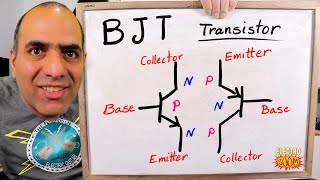
I do wonder where the names base, collector, emitter and gate, drain and source comes from and why they are different with each transistor type.
I am not sure about that but I think those names are originated from their behavior.
e.g. by applying voltage to gate terminal it act like opening a gate.
خیلی دوستت دارم، استاد. ❤️💖❤️💓💖❤️
I love you too dude❤️
Why the focus on switching, what about small signal amplification?
Yeah, it is another world
i would love to see a vid about voltage regulators. at the minute im making a battery powered laser and my circuit uses 3 lm317s. i get 12v via a decoy usb cable i made, then it is limited by 1 lm317 to 10volts, then a second one limits to 700mA, that is fed into two 18650 cells, the output of which goes to a 3rd lm317 to limit current to 1.5 amps to not kill my laser diode. then i use a bd139 driven by a switch to turn laser on and off. no doubt this isnt the best way to do it, but it is my way. i am only doing this for learning, if i needed a laser pointer i'd buy one. i just like making stuff. is my method of using 3 lm317s sensible or daft?
So nice, thanks for sharing 👍
Awesome video
Glad you enjoyed it
love your videos
Thank you so much, keep watching😉
I am a novice in electronics. I want to drive a relay 5v board HIGH trigger (needs 5v), from rcwl-0516 trigger out of 3.7v. or in another case, a 12v relay board of LOW trigger. (In this case, completing the relay trigger to relay earth switches on). Can you please help me whether a MOSFET or bjt it better?, npn or pnp required? and finally which pin emitter/collecter/etc to connect in which way, and whether diode or resistor is required in any part of the base pin? Thank you. You are very clear in your videos and I learn from you!
Did you see this video?
th-cam.com/video/L0QraSYq8tw/w-d-xo.html
I have answered many of your questions there
@@elewizard I had missed it. Thank you very very much brother. Can you clarify if I put a led between trigger and ground (ie on 12v relay, LOW) OF THE RELAY that will be ok ? Or should I put any diode in base to prevent back flow? And any resistor after the transistor to complete the earth? I think the relay board trigger is live at 2v default state. And I'm "shorting" this to relay earth via the transistor. If that makes sense
So in essence , the base connected to sensor trigger 3.7v out. The emitter to led to 12v relay trigger 2v and the collector to relay earth. Am I correct?
Loved it.
Thank you!
nice
Very nice
Thank you
You're welcome
😅
I can't figured it out if current or voltage are separate can you give me some explanation because but is triggered by current and mksfet are voltage
So if controlling with an microcontroller are you saying once turned on it will remain on? What drains the gate so that it isn’t stuck on? When the controller turns the output off it sinks instead of sourcing and removes the charge from the gate? Guess the speed at which you can switch is influenced by how fast you can charge and discharge gate. How does that relate to a bjt?
Yes, MCUs sink the output and discharge the gate cap. On low speed switching, the amount of current needed to switch MOSFET on or off is so low compared to BJT in same power.
@@elewizard MCU has max sink current, how to determine the mosfet cap discharge current?
@@xGen720 You always drive a mosfet gate via a low value resistor, typically around 100R, for a couple of reasons. The driver may be an MCU and will switch very fast, so the gate-source capacitance of the mosfet looks like an instantaneous short-circuit. You therefore include a series resistor to limit that initial current rush. At 3.3V, 100R will limit the current to less than 33mA. In addition, a very fast rising edge driving the stray inductance in the circuit along with Cgs will often cause the LC circuit to "ring" or even oscillate. A series resistor will damp out that ringing, at the expense of limiting the maximum switching speed.
when you have many components on PSB you sink voltage faster than when you've just one component,on and off will be very effective because other components use the same GND
@@RexxSchneider
So for example to limit to 10ma as my mcu specs say that is the max, a 330Ohm resistor. would be used. Then I would have to take into consideration the capacitance of the mosfet gate and the time it takes to get to the gate threshold etc, to find out the max switching speed. Glad we have programs like excel to help and the internet. Should a pull down resistor also be used to drain the capacitance quicker? If so, now there is a voltage divider that further complicates it. Is there a good rule of thumb that for an mcu once you hit some speed requirement you should just consider using a mosfet driver?
So Mosfets are better at modulated by microcontrollers than any other type of transistors?
No, it depends on the application and particular project you are working on.
@@elewizard Thanks for the reply, how can I make a circuit which can modulate a laser at 5-30KHz?
@@ShopperPlug you can use an LDR as receiver. Then you can use any modulation you want. A simple modulation like PWM or complex modulations.
@@elewizard Thanks for the reply, I would like to use Laser for engraving using CNC machine. Not sure how to make the circuit for low powered UV laser so that I can make PCB boards using UV photo-lithography.
In your diagram there should be a resistor from the gate to GND. Otherwise the gate will be floating when the switch is open, and the MOSFET will be in an unpredictable state.
The mosfet will remain ON for a while 👍
@@elewizard True. But how long it will remain on is unpredictable. It could even depend on the humidity of the air. Also, the MOSFET could be damaged by static discharge. Personally, I do not recommend this circuit. But it is interesting to think about. Thank you for posting it :-)
I am a little lost about how to use bjt's ..doesnt current depends on load ? how do I control current then ?
Watch the last video on the channel and wait for the upcoming video to get the answer
@elewizard It was a really great video, man. Keep up the great work, and I wish you to grow more 👍
Thank you dude.
I will keep the hard work.
Thank you for the encouragement 😊
3:16 - A mosfet does not have a "gate-source junction". Same mistake is repeated thereafter several times.
7:32 - Mosfets *DO* need current to turn on or off, especially when switching. That's why we have mosfet drivers. They simply don't need current to *STAY* on or off, but that's not relevant. You get it right in your summary at the end.
You failed to make the main point in favour of using mosfets for high current switching and that is the low Vds when fully on compared to a comparable BJT, resulting in much lower power dissipation in the device. An IRFZ44 mosfet passing 2A will typically have around 60mV across it, for a power dissipation of 120mW. A TIP120 Darlington BJT would have Vce(sat) over 1V at Ic=2A, with a dissipation of 2W. A TIP41 BJT at Ic=2A would typically have Vce(sat) around 200mV, with a dissipation (400mW) closer to that of a mosfet, but it would require a base current of 200mA to achieve that, so it's really not comparable.
Thank you for these important points that you mentioned!
Subscribed.
You are most welcome!
I'm learning how to use MOSFETs and still a bit confused about datasheets choosing the right one.
I will do a video about this subject. How to select right transistor for particular application. 😉
thanks.@@elewizard
Yes would be interesting a video tutorial how to read a datasheet of an ic / electronic component
خیلی عالی
Thanks ❤️
powerful mosfets can require very high pulse current at the moment of switching. And not mentioning it at all is not good.
Yes, in high frequency the amount of current going to gate or comming out of that is high 👍
It is subject of a video that I am planning to do
You are not using 5v to open the gate in the example
Transistors drive me crazy
Transistors are amazing!
Too simple... in high current the output resistance is much lower than bjt.
Yes, in most cases that is true
Not necessarily. The IRF530 mentioned in the video has an Rds(on) of the order of 160mΩ when fully driven on. At 4A that's a Vds of 640mV, so a power dissipation of 2.5W. The TIP41 shown in the video will have a typical Vce(sat) of 300mV at Ic=4A, giving a power dissipation of 1.2W. Of course, there are mosfets with much lower Rds(on), but you have to make sure you specify one if you want to get an improvement over a typical BJT.
[Edit:] Actually the video mentions the IRF630, which has an Rds(on) as high as 300mΩ, so you might have to dissipate almost 5W at Id=4A.
Are you TURkish??
Somehow 🤪
Thank you, sir! :)
You're welcome!
Wonderful 🎉🎉🎉🎉many thanks ❤❤❤❤
Thank you too!
Mosfets are superior in MOST cases, including RF!
👍
Not if you're driving a switching circuit from a low voltage supply such as a 3.3V MCU (and definitely not if it's a 1.8V MCU). You'll always have enough output voltage to fully turn on a BJT, but very few mosfets will guarantee being fully turned on with something like 3V on the gate. Of course, you can use a level-shifter/driver for the mosfet, but the BJT often gives a simpler circuit.
I did say "most cases", but not wanting to sound shitty here, but very low gate voltage mosfets are easy and cheap (except for high power), I use such mosfets often with MCU running from a 3V battery (meaning 2.4V voltage must work reliably). a 1.8V MCU would be difficult, but there are some mosfets that work work at that voltage as well, and yeas, still cheap, because even for 1.8V operations, such mosfets are in high demand. Having said all that, I use BJTs, something like 1:4 bjt:mosfet ratio, so I have nothing against them. I grew up on bjt from the 70's, and even some valves (tubes)! BJTs have a large place in electronics today, it's just that mosfets are the very much more used. As for simpler circuit, the same can be said in the reverse, it all depends on what you are doing, so please, lets not go down that path, they both have their place and advantages and otherwise.
btw, even though I do some low voltage battery MCU stuff, I mostly don't, but here is a cheap and very common smaller "power" mosfet (48mOhm) the Alpha and Omega AO3400 (second sourced by a laundry list of manufacturers), it works down to a gate voltage of 2.5V, guaranteed by the manufacturer. There are mosfets that go even lower like the ever common 8205 used in battery protection circuits, also cheap as chips and at 1.8V is 75mO. I have never neaded anything lower, but I am sure they exist. Also keep in mid, mosfets work on voltage, not no current being wasted when turned on like BJTs are. Like I said, both have their place, just mosfets are very much more common.
@@stevenbliss989 I've used the AO3400, but it's not much use for higher current applications, particularly when the Vgs=2.5V on-resistance is specified at 3A, so you don't know for certain what it will be at higher currents. Note that the maximum on-resistance at Vgs=2.5V is 50% higher than at 4.5V, so it's not "fully on" as I originally said.
On the other hand, I can easily drive a Sziklai pair into saturation from 1.8V and sink tens of amps with decent heatsinking. As you say, it's horses for courses, but low Vgs, high current mosfets aren't easy to find.