Hi Sam, I think the answer to your question (what is the different between HB with one or two Capacitors) is the following - 1. from the voltage rating of the capacitor there is no change - in both option the capacitors would have about Vin/2 stress as long as the duty cycle on time is equal between the switches 2. from the current rating of the capacitors there is a different - taking only one cap (low cap or high cap, both options are valid) would result in a. the transformer current would be identical to the capacitor current instead of a combination of both capacitors current - higher RMS current rating for one cap solution b. the main current would be the same as the transformer in one switch operation and 0A on the other switch operation (only one switch would enable to close a circuit between Vin to GND) resulting in a higher RMS current comparing to the two capacitors solution that would enable main current to flow at both switches operation
About the riddle at 11:30, about the difference between the single and the double capacitors, I did not see any satisfying solution yet, so let me give it a try : I think the double (split) capacitors serve as the capacitor that you need over the Vin lines, to close the main switch loop. With the single capacitor, you would still need a separate bulk capacitor of Vin, so it makes sense to split that cap into the configuration that Dr. Steigerwald proposed.
Brilliant explanation Sir! Just regarding your question in 11:31. What I think about the difference between the two is that, the one with the two bulk capacitors has its bulk capacitors rated as half of the input voltage, at least (i.e. switches a rated as half of the input voltage). Where as the other one is rated as the input voltage (i.e. switches a rated as the input voltage). Correct me if I'm wrong Sir, thanks. Looking forward for Part 2
Dear All. I consider that using split capacitors the converter can force current in both directions. Therefere, it turns out as a better transformer utilization; the converter, related to the transformer, does not only opperate in one quadrant. Comments are welcome. Regards,
What is the benefit of the resonance around a transformer? I see the secundairy voltage is very high but it draws a very high current from the supply ánd when i load it, draw current from the secundairy, strange the primairy draws less current from the supply. Or is that only because it is then not longer in resonance? So can resonance then only be usefull for only one loadcurrent by wich the frequency gives the highest outputvoltage or current and where is then the benefit compared with a frequency higher or lower than driving the transformer on his own resonance frequency? This behavior from a co2lasertrafo i saw and i choose a lower frequency in spite of a lower outputvoltage. The current behaves more normal then, so lower supply load when lower transformerload. Should i better choose the resonance frequency(depending on the load, the transformer resonances with a very high outputvoltage on 22to46kHz)
Hi Rob, Thanks for input. I will cover these issues (advantages and deficiencies)in the next parts of tutorial. Let just say at this point that one of the problems with LLC is indeed higher current stresses at the output.
@@sambenyaakov thanks again! Much of your lessons is so usefull for me that it became really a longtime wish come true (if that is good english?) Now I look out for your next video even more than normally. So great that you can make this lessons on youtube!
Still, if you short the primary of transformer nothing drastic would happen (like a current source). In the case of a parallel loaded converter, if you short the primary of transformer....(voltage source).
Hi Sam, a nice day or maybe evening there, I have a question what I can not answer myselfs. The LCC converter has a different relationship with the transformer, Can you explane in some words how to design the transformer itselfs? In LCC the capacitors do devide impedances?. Can I use a normal half bridge transformer calculator? I read little about it. Thanks in advance.
@@sambenyaakov This question is now clear, I need to involve the transformer on a right way, with the Cp capacitor making a second resonance point. The Cs and Cp has tow frequency's, one on Cs and Lr and one on Cp + CS and Lr and transformer for the gain setup. look like LLC where the leakage of transformer is used as Cp. I get the most output when I am on the peak of graph, .
can some one plz explain 14:00 , how stigerwald calculated these equations, i am stuck on this watched too many '" full bridge rectifier videos for calaculation of rms ,and average value , but how stigerwald bring 2.squareroot 2. @ @ Sam Ben -Yaakov
See his original paper R. L. Steigerwald, "A comparison of half-bridge resonant converter topologies," in IEEE Transactions on Power Electronics, vol. 3, no. 2, pp. 174-182, April 1988, doi: 10.1109/63.4347.
The input RMS current drawn is reduced using the split capacitor network. The stress on each cap is low and also the voltage rating chosen can be low. May be you can explain this better Dr. Sam: I read in an app note that the split capacitor can reduce the possibility of hard commutation during startup of the LLC ( one of the failure modes of LLC is startup). The amount of time required to charge the split capacitor is low and the transformer is not driven symmetrically until the resonant cap is charged. And this can lead to hard commutation. This is somehow reduced using the split capacitor network although not completely eliminated. Page-11 section 2.4 : www.infineon.com/dgdl/Infineon-Application+Note+Design+of+a+600+W+HB+LLC+Converter+using+CoolMOS%E2%84%A2+P6-AN-v01_00-EN.pdf?fileId=5546d4624f205c9a014f2713b91512f5
Hi Swaraj, Thanks for comment and for the reference which I will read. I rather not give you a grade , yet 😊, as I am hoping that others will also respond. It seems that a short video on the subject could be useful. Thanks again.
Hi Professor. I have in time done some tryouts in simulation I have now a model for FHA analysis so I see much o more, I can do LCC and LLC with it in LTspice. I have some questions about the LCC, the transformer is known now, it is part of how the CS Lr and Cp are done and loaded with it, it is not just a big inductance but work with Cp impedance. I see some papers where the Cp is twice the Cs while I see most of the others have lower Cs then Cp sometimes even a factor ten, I did see that when I do that I need a smaller inductance for the transformer, for lower mosfet current, transformer N is important against losses, I get with Cs 27n Cs 2.7 n and a Lr of 100 uH on 100 Khz what is 100 Khz and 60 Khz, (current output) and (60 Khz to 100Khz voltage output) the peak do just flip, I use the high peak and above, and all output voltages 20v 15 amp, 150 + 150 volts 126mA and 350 volts 100mA give a mosfet current of 4.5 amps with a startup of 40 amps!!! oi yes that is what resonance supply do with startup, dangerous high amps, boom, soooo much need of soft start. but when ready 4.5 amps left and have a nice half sinus mosfet current signal.. When I do lower the 20 volts 15 to 100 mA I get a primary mosfet current of 1.2 A with all other outputs on normal currents. I do see that with 15 amps I get 22 volts out and with 100 mA I get 23.5 volts, without any regulation, this makes it an excellent audio power supply, better the LLC in this. The mosfet current changes with low load to a kind of strange positive quarter wave and a sharp plus in the negative part. With load it changes to half sinusoidals. I have use a Q of 6.2 on Lr and Cs. I use this too for that, www.omnicalculator.com/physics/rlc-circuit. Oke update, I did a open output, what happens then is the HV voltages go from 350 to 550 volts and the 150 volts to 200 volts, but the low 20 volts 30 volts, a little load is enough to get them from stop running up and up. I did hear this is inherent of LCC. Mosfet current is now 1.5 amps. I gess loss because of circulation currents, as this is the case then it is low. So need a regulation, no problem, that already did work. Regards
@@sambenyaakov I am ready for build, the inductance meter is here, and is quite needed to make the transformer. I have not done the LLC for test, I did simulate it and calculate the value,s I did get some info about the Q factor, these I have set such, that when full power the resonance capacitor has not to high voltage, in mine case now, 800 volts when start up hard, and 240 volts when in lock and on right voltages. I can go as low as 100mA in output and still does regulate, lower can not, I get to high circulating currents. In mine case now, I have 300 volts input, no pfc, and the supply does be close to resonance getting a nice sinusoidal on transformer. When full power, that is 19 volts 10 amps, 350 volts 105 mA and 130 plus 130 volts 300 mA I get a primary current of 3.5 amps. When at lowest I get 0.8 to 1 amp. This is on simulation, not the build, but simulation these days with good models is scary precise. A pfc can maybe be needed to get a more clean input voltage, but I have a low power supply so maybe not needed. I will make a small video to show you all the signals soon. The LCC do better with high voltages but never it has to go open because then, the high voltage get so high the tubes will be damaged. I need for LCC a voltage protection when use that, but LLC can also do the high voltages, even when pro,s say it is not suitable. I have now all the info, I do now what to do and all thanks to your very clear and clean video,s Tanks for that. Q and transformer has a very narrow band with each other, this I did miss.
@@sambenyaakov Well this was what I did miss for transformer calculation. if primary known, just do for secondary (1\N)squared x primary inductance did the trick, I did search for. Again learned something.
Thanks for another great video! I have question about first harmonic simulation: What with dead time? Dead time have big impact on circuit, and first harmonic simulation don't show it. Can we consider dead time in this type of simulation? Best regards, Marcin
@@sambenyaakov Thanks for answer I ask about dead time because I use first harmonic idea in algorithm to find rezonant frequency (measure current from current transformer and do fft and atan2): th-cam.com/video/VRjyxihpBYU/w-d-xo.html blue - rectified current yellow - driving signal from uC Then I find out a dead time have impact on frequency that I need use, if I use theoretical resonant parameters (high first harmonic amplitude and 0 degree phase) I hadn't ZVS, because mosfet open with delay with hard switch: th-cam.com/video/TAbC0UGfC3c/w-d-xo.html When I add some detuning in frequency (a bit higher freqency) I got ZVS. This detuning depend on dead time value (dead time projected to phase for resonant frequency). If I use low Q in circuit then it was ok, but if I would use some biger value, this problem with dead time could be bigger. Do you know about documents says about dead time impact on resonant frequency? Best regards, Marcin
Hi Marcin, Perhaps the issue here is phase shift not the the magnitude off first harmonics. No specific document comes to my mind on this. Please share your findings at www.linkedin.com/groups/13606756/
Dear Professor Ben-Yaakov, i have a question regarding 26:45 : Where has the magnetizing inductance gone in the linear model? Can it be eliminated that easily? Regards?
Good point. This model assumes, as in most first order analyses, that the magnetization inductance of the transformer is high and thus does not affect much the circuit operation.
@@sambenyaakov Sorry for break in here, I have not seen this, reading more posts helps, but I am sure not the only one. That is why I can just calculate the transformer with a tool, and use that normal half bridge setup. I think just calculate the X of the transformer and keeps it high enough, above reactance of tank but not to high will help. In papers was also mentioned that X or inductance transformer has to be high enough, that is because the LCC tank output act as a current source. But not to high tough. ChatGPT was wrong here so AI needs to learn more also;-). regards


![จบจนได้ ! | Black Myth: Wukong #007 [ตอนจบ?]](http://i.ytimg.com/vi/DSqvWndF0sw/mqdefault.jpg)

![[LIVE] : ONE ลุมพินี 76 | คู่เอก "ผึ้งหลวง vs สมิงดำ"](http://i.ytimg.com/vi/9SBshmGQOIM/mqdefault.jpg)

Thank for lectures prof. Ben-Yaakov. Great explanations!
Thanks.
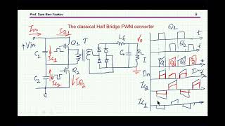
Hi Sam, I think the answer to your question (what is the different between HB with one or two Capacitors) is the following -
1. from the voltage rating of the capacitor there is no change - in both option the capacitors would have about Vin/2 stress as long as the duty cycle on time is equal between the switches
2. from the current rating of the capacitors there is a different - taking only one cap (low cap or high cap, both options are valid) would result in
a. the transformer current would be identical to the capacitor current instead of a combination of both capacitors current - higher RMS current rating for one cap solution
b. the main current would be the same as the transformer in one switch operation and 0A on the other switch operation (only one switch would enable to close a circuit between Vin to GND) resulting in a higher RMS current comparing to the two capacitors solution that would enable main current to flow at both switches operation
About the riddle at 11:30, about the difference between the single and the double capacitors, I did not see any satisfying solution yet, so let me give it a try :
I think the double (split) capacitors serve as the capacitor that you need over the Vin lines, to close the main switch loop.
With the single capacitor, you would still need a separate bulk capacitor of Vin, so it makes sense to split that cap into the configuration that Dr. Steigerwald proposed.
Have you seen th-cam.com/video/T8qWWwsMOK8/w-d-xo.html ?
@@sambenyaakov Ah ! Thank you. Your attention to details is phenomenal. Love your work Dr. Ben-Yaakov.
@@2meters2 😊🙏
Having recently taken apart a few PC power supplies recently, the half bridge designs have just a single DC blocking capacitor.
Still, having two capacitor has an advantage. Waiting for additional responses 😊
Brilliant explanation Sir! Just regarding your question in 11:31. What I think about the difference between the two is that, the one with the two bulk capacitors has its bulk capacitors rated as half of the input voltage, at least (i.e. switches a rated as half of the input voltage). Where as the other one is rated as the input voltage (i.e. switches a rated as the input voltage). Correct me if I'm wrong Sir, thanks. Looking forward for Part 2
The question of capacitor voltage rating could be a reason in case of very high voltage bus but there are other reasons for two capacitors.
Thanks Doctor Sam
😊
Dear All. I consider that using split capacitors the converter can force current in both directions. Therefere, it turns out as a better transformer utilization; the converter, related to the transformer, does not only opperate in one quadrant. Comments are welcome. Regards,
It makes no difference to the transformer if one or two capacitors are used.
1:30 Does the inductance of the isolation transformer affect the tank resonance?
Yes, it is the second L of the LLC
Awesome
😊
What is the benefit of the resonance around a transformer?
I see the secundairy voltage is very high but it draws a very high current from the supply ánd when i load it, draw current from the secundairy, strange the primairy draws less current from the supply. Or is that only because it is then not longer in resonance? So can resonance then only be usefull for only one loadcurrent by wich the frequency gives the highest outputvoltage or current and where is then the benefit compared with a frequency higher or lower than driving the transformer on his own resonance frequency? This behavior from a co2lasertrafo i saw and i choose a lower frequency in spite of a lower outputvoltage. The current behaves more normal then, so lower supply load when lower transformerload. Should i better choose the resonance frequency(depending on the load, the transformer resonances with a very high outputvoltage on 22to46kHz)
Hi Rob, Thanks for input. I will cover these issues (advantages and deficiencies)in the next parts of tutorial. Let just say at this point that one of the problems with LLC is indeed higher current stresses at the output.
@@sambenyaakov thanks again! Much of your lessons is so usefull for me that it became really a longtime wish come true (if that is good english?) Now I look out for your next video even more than normally. So great that you can make this lessons on youtube!
Sam Ben-Yaakov Morning
Great video! only 1 thing at 12:18, would the source impedance not be more like a reactive source than a current source?
Still, if you short the primary of transformer nothing drastic would happen (like a current source). In the case of a parallel loaded converter, if you short the primary of transformer....(voltage source).
Hi Sam, a nice day or maybe evening there, I have a question what I can not answer myselfs. The LCC converter has a different relationship with the transformer, Can you explane in some words how to design the transformer itselfs? In LCC the capacitors do devide impedances?. Can I use a normal half bridge transformer calculator? I read little about it. Thanks in advance.
Thank for sharing your thoughts Losses may higher thogh.
@@audiokees4045 👍
@@sambenyaakov This question is now clear, I need to involve the transformer on a right way, with the Cp capacitor making a second resonance point. The Cs and Cp has tow frequency's, one on Cs and Lr and one on Cp + CS and Lr and transformer for the gain setup. look like LLC where the leakage of transformer is used as Cp. I get the most output when I am on the peak of graph, .
can some one plz explain 14:00 , how stigerwald calculated these equations, i am stuck on this watched too many '" full bridge rectifier videos for calaculation of rms ,and average value , but how stigerwald bring 2.squareroot 2. @ @ Sam Ben -Yaakov
See his original paper R. L. Steigerwald, "A comparison of half-bridge resonant converter topologies," in IEEE Transactions on Power Electronics, vol. 3, no. 2, pp. 174-182, April 1988, doi: 10.1109/63.4347.
The input RMS current drawn is reduced using the split capacitor network. The stress on each cap is low and also the voltage rating chosen can be low. May be you can explain this better Dr. Sam: I read in an app note that the split capacitor can reduce the possibility of hard commutation during startup of the LLC ( one of the failure modes of LLC is startup). The amount of time required to charge the split capacitor is low and the transformer is not driven symmetrically until the resonant cap is charged. And this can lead to hard commutation. This is somehow reduced using the split capacitor network although not completely eliminated. Page-11 section 2.4 : www.infineon.com/dgdl/Infineon-Application+Note+Design+of+a+600+W+HB+LLC+Converter+using+CoolMOS%E2%84%A2+P6-AN-v01_00-EN.pdf?fileId=5546d4624f205c9a014f2713b91512f5
Hi Swaraj, Thanks for comment and for the reference which I will read. I rather not give you a grade , yet 😊, as I am hoping that others will also respond. It seems that a short video on the subject could be useful. Thanks again.
Hi Professor. I have in time done some tryouts in simulation I have now a model for FHA analysis so I see much o more, I can do LCC and LLC with it in LTspice.
I have some questions about the LCC, the transformer is known now, it is part of how the CS Lr and Cp are done and loaded with it, it is not just a big inductance but work with Cp impedance. I see some papers where the Cp is twice the Cs while I see most of the others have lower Cs then Cp sometimes even a factor ten, I did see that when I do that I need a smaller inductance for the transformer, for lower mosfet current, transformer N is important against losses, I get with Cs 27n Cs 2.7 n and a Lr of 100 uH on 100 Khz what is 100 Khz and 60 Khz, (current output) and (60 Khz to 100Khz voltage output) the peak do just flip, I use the high peak and above, and all output voltages 20v 15 amp, 150 + 150 volts 126mA and 350 volts 100mA give a mosfet current of 4.5 amps with a startup of 40 amps!!! oi yes that is what resonance supply do with startup, dangerous high amps, boom, soooo much need of soft start. but when ready 4.5 amps left and have a nice half sinus mosfet current signal..
When I do lower the 20 volts 15 to 100 mA I get a primary mosfet current of 1.2 A with all other outputs on normal currents. I do see that with 15 amps I get 22 volts out and with 100 mA I get 23.5 volts, without any regulation, this makes it an excellent audio power supply, better the LLC in this.
The mosfet current changes with low load to a kind of strange positive quarter wave and a sharp plus in the negative part. With load it changes to half sinusoidals. I have use a Q of 6.2 on Lr and Cs. I use this too for that, www.omnicalculator.com/physics/rlc-circuit.
Oke update, I did a open output, what happens then is the HV voltages go from 350 to 550 volts and the 150 volts to 200 volts, but the low 20 volts 30 volts, a little load is enough to get them from stop running up and up. I did hear this is inherent of LCC. Mosfet current is now 1.5 amps. I gess loss because of circulation currents, as this is the case then it is low. So need a regulation, no problem, that already did work.
Regards
Is it up and running?
@@sambenyaakov I am ready for build, the inductance meter is here, and is quite needed to make the transformer. I have not done the LLC for test, I did simulate it and calculate the value,s I did get some info about the Q factor, these I have set such, that when full power the resonance capacitor has not to high voltage, in mine case now, 800 volts when start up hard, and 240 volts when in lock and on right voltages. I can go as low as 100mA in output and still does regulate, lower can not, I get to high circulating currents. In mine case now, I have 300 volts input, no pfc, and the supply does be close to resonance getting a nice sinusoidal on transformer.
When full power, that is 19 volts 10 amps, 350 volts 105 mA and 130 plus 130 volts 300 mA I get a primary current of 3.5 amps. When at lowest I get 0.8 to 1 amp. This is on simulation, not the build, but simulation these days with good models is scary precise. A pfc can maybe be needed to get a more clean input voltage, but I have a low power supply so maybe not needed. I will make a small video to show you all the signals soon.
The LCC do better with high voltages but never it has to go open because then, the high voltage get so high the tubes will be damaged. I need for LCC a voltage protection when use that, but LLC can also do the high voltages, even when pro,s say it is not suitable.
I have now all the info, I do now what to do and all thanks to your very clear and clean video,s Tanks for that. Q and transformer has a very narrow band with each other, this I did miss.
@@audiokees4045 Thanks for sharing
@@sambenyaakov Well this was what I did miss for transformer calculation. if primary known, just do for secondary (1\N)squared x primary inductance did the trick, I did search for. Again learned something.
Before Lr and Cr why u have given ac signal ..in equivalent circuit ?? Please reply sir
To which minute are you referring?
Thanks for another great video!
I have question about first harmonic simulation: What with dead time? Dead time have big impact on circuit, and first harmonic simulation don't show it. Can we consider dead time in this type of simulation?
Best regards,
Marcin
In ZVS soft switching dead time has skittle effect since the voltage waveform is still symmetrical (if the two dead times are about the same length).
@@sambenyaakov Thanks for answer
I ask about dead time because I use first harmonic idea in algorithm to find rezonant frequency (measure current from current transformer and do fft and atan2):
th-cam.com/video/VRjyxihpBYU/w-d-xo.html
blue - rectified current
yellow - driving signal from uC
Then I find out a dead time have impact on frequency that I need use, if I use theoretical resonant parameters (high first harmonic amplitude and 0 degree phase) I hadn't ZVS, because mosfet open with delay with hard switch:
th-cam.com/video/TAbC0UGfC3c/w-d-xo.html
When I add some detuning in frequency (a bit higher freqency) I got ZVS. This detuning depend on dead time value (dead time projected to phase for resonant frequency). If I use low Q in circuit then it was ok, but if I would use some biger value, this problem with dead time could be bigger.
Do you know about documents says about dead time impact on resonant frequency?
Best regards,
Marcin
Hi Marcin, Perhaps the issue here is phase shift not the the magnitude off first harmonics. No specific document comes to my mind on this. Please share your findings at www.linkedin.com/groups/13606756/
Dear Professor Ben-Yaakov,
i have a question regarding 26:45 :
Where has the magnetizing inductance gone in the linear model? Can it be eliminated that easily?
Regards?
Good point. This model assumes, as in most first order analyses, that the magnetization inductance of the transformer is high and thus does not affect much the circuit operation.
@@sambenyaakov Sorry for break in here, I have not seen this, reading more posts helps, but I am sure not the only one. That is why I can just calculate the transformer with a tool, and use that normal half bridge setup. I think just calculate the X of the transformer and keeps it high enough, above reactance of tank but not to high will help.
In papers was also mentioned that X or inductance transformer has to be high enough, that is because the LCC tank output act as a current source. But not to high tough. ChatGPT was wrong here so AI needs to learn more also;-).
regards
ohh... I see you have publish an answer. I would watch that and see how far I was from the answer (-:
👍👍
מה שלומך?
@@sambenyaakov הכל מצויין! עובד, לומד ונהנה מכל רגע.
@@ezranoam 👍