TH-cam
US
12 Volt Automatic Cut-Off Smart Battery Charging Circuit - New Design
7:06
Make a 12v Battery charger with auto cut off, using UPS Transformer
11:17
New 12V Battery Charger Circuit! No Setting, Battery Status Indicator, Full Charge Audible Warning
8:02
ร้องเพลงสั่งข้าว Ver.សង្រ្កាន្តស្គាល់ស្នេហ៍ (SANGKRAN MAGIC) - VANNDA #vannda #ร้องเพลงสั่งข้าว
00:45
SAFEPLANET - ดาวเคราะห์ [ THE PLANET ]
04:00
วิธีทำให้ 8 วินาที เหลือแค่ 1 วินาที
00:41
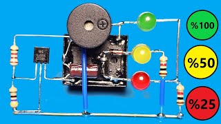
Simple 12 volt Battery charger Automatic cut off, 12v auto cut off battery charger
Creative Techos
ติดตาม
151K
ดาวน์โหลด
โหลดลิงค์.....
มุมมอง 183 819
0
0
เพิ่มลงใน
เพลย์ลิสต์ของฉัน
ดูภายหลัง
แชร์
แชร์
ฝัง
ขนาดวิดีโอ:
1280 X 720
853 X 480
640 X 360
แสดงแผงควบคุมโปรแกรมเล่น
เล่นอัตโนมัติ
เล่นใหม่
เผยแพร่เมื่อ 26 พ.ย. 2024
ความคิดเห็น • 74
ต่อไป
เล่นอัตโนมัติ
7:06
12 Volt Automatic Cut-Off Smart Battery Charging Circuit - New Design
ZAFER YILDIZ
มุมมอง 92K
11:17
Make a 12v Battery charger with auto cut off, using UPS Transformer
Homemade 101
มุมมอง 296K
8:02
New 12V Battery Charger Circuit! No Setting, Battery Status Indicator, Full Charge Audible Warning
ZAFER YILDIZ
มุมมอง 99K
00:45
ร้องเพลงสั่งข้าว Ver.សង្រ្កាន្តស្គាល់ស្នេហ៍ (SANGKRAN MAGIC) - VANNDA #vannda #ร้องเพลงสั่งข้าว
Bie The Ska
มุมมอง 2.9M
04:00
SAFEPLANET - ดาวเคราะห์ [ THE PLANET ]
safeplanet
มุมมอง 82K
00:41
วิธีทำให้ 8 วินาที เหลือแค่ 1 วินาที
Filllykung
มุมมอง 156K
19:59
ทำไม อดีต สว.มั่นใจว่า สีน้ำเงินไม่มีอำนาจต่อรอง และเหตุใด'รัฐบาลเพื่อไทย' อยู่รอดครบเทอมแน่ ?!
มติชนสุดสัปดาห์ - MatichonWeekly
มุมมอง 106K
10:51
So Don't Throw Your Old Phone Charger Away! - More Than You Think !
Creative Techos
มุมมอง 94K
7:59
Making a Smart Battery Charger | Charge Any kind of battery with Auto Cut off Protection
Next Builder
มุมมอง 12K
27:57
Не покупай GaN зарядку пока не посмотришь этот тест!
Lisin YT
มุมมอง 512K
8:17
Automatic Cut-Off Battery Charger - Making a Battery Charger at Home - great idea for you
ZAFER YILDIZ
มุมมอง 1.1M
13:15
Carregador Automotivo 12v! CASEIRÃO (CONTROLADOR DE CARGA)
Canal XProjetos
มุมมอง 109K
17:58
BQ25606 - Модуль зарядки лития который все ждали.
arduinoLab
มุมมอง 52K
15:11
How to make a simple welding machine from SPARK PLUG at home! Genius invention
Creative Passion 88
มุมมอง 3M
5:11
Automatic Cut Off 12v Battery Charger #12v battery #charger #viral #battery charger
Creative NS
มุมมอง 531K
6:53
So Don't Throw Your Old Phone Charger Away! - More Than You Think
ZAFER YILDIZ
มุมมอง 1.1M
00:45
เพื่อนผมมันทำได้ไง มันทำไม่ได้ไม่ใช่หรอ?? | Minecraft #minecraft #มายคราฟ #fypシ #minecraftmemes #ตลก
Kyoro Danger
มุมมอง 129K
3:29:04
MISS GRAND KHON KAEN / PHATTHALUNG 2025 | FINAL SHOW
GrandTV
มุมมอง 405K
3:55:22
แครี่คุณภาพแห่งวงการ ROV
HEARTROCKER
มุมมอง 790K
06:13
น้ำใจสาวช่องเม็ก (ນ້ຳໃຈສາວຊ່ອງເມກ) - กีต้าร์ นิภาพร【OFFICIAL MV】#ช่องเม็กเดอะซีรีส์
GRAMMY GOLD OFFICIAL
มุมมอง 225K
1:42:49
🔴Live โหนกระแส แอมจ๋าพัชลาก่อน โบกมือลาเสียงเพลงครวญมาต้องลาแล้วเพื่อน
โหนกระแส [Hone-Krasae] official
มุมมอง 1.1M
2:45:16
สาวยากจนเสนอว่าจะดูแลพนักงานเสิร์ฟ โดยไม่รู้ว่าเขาเป็นคนรวยที่สุดในโลก
Shop ละคร
มุมมอง 1.2M
00:11
Thank you Santa Clause
Nadir Show
มุมมอง 10M
23:30
กินแปลกประเทศจีน สตรีทฟู้ดฉงชิ่ง 24 ชั่วโมง BANKII 8K
BANKII
มุมมอง 351K


![SAFEPLANET - ดาวเคราะห์ [ THE PLANET ]](http://i.ytimg.com/vi/4X1XL3I_k3c/mqdefault.jpg)


