I just used this video to solder a nub of wire onto the PCB i pulled from a cheap BT speaker which I have soldered onto audio leads to add wireless sound to my old-school stereo receiver at work. It used to have an unobstructed range of maybe 5 feet, and would drop signal from 2 feet away through one layer of plywood office wall. Now it stays solid clear across the garage (about 15 ft.) and keeps playing through the plywood wall with no drops! Well done, mate. Good video - very useful for the home tinkerer who may not have the micro-soldering equipment required by other videos on the subject!
Whenever you're making an antenna (or extension) you do NOT CUT FIRST THEN SOLDER, you always take a bit more wire than needed and SOLDER THEN CUT the wire to the correct length ... Otherwise the amount of wire overlapped onto the PCB trace (or original antenna wire) is a loss from the overall resulting length and at 2.4 GHz a little bit makes a big difference (it's even more picky at 5.8 GHz) .
I've done this to an ESP32 and it worked really well. I soldered a 3 pin female header between the ANT connection and ground with the remaining pin soldered to the disconnected meandered trace for additional mechanical support. I also added a liberal blob of epoxy as its pretty easy to pull those traces of the board. I just stuck a couple bits of hookup wire in the sockets as antennae. Using a straight monopole and a quasi-dipole (another monopole connected to gnd) both gave similar performance. I remember one network's RSSI had been ~ -70dBm prior to the mod and -45 afterward. As far as the NRF goes though, you're better off just buying the version with a power amp and SMA connector and screwing a rubber ducky from an old router on to it.
It work really nice with this modification. I have tested it and the signal goes better and lost packet goes lower. So this solution is great for increasing the performance.
This is totally wrong, sorry. The pcb antenna is calculated to match with the tcvr, and you just can't measure it's length! There are a lot of things like shortening factors, imedance, and other stuffs you have to calculate in. With this mod, i'm sure you unmatch the impedance, and at a higher transmit powers (like PA+LNA version) it could kill your transmitter! If you want to do the correct way, you should disconnect the entire antenna with a cut after 2-3mm, and solder a wire antenna on. The proper size should be l=((C/F)/4)*0.96, where C is 300, F is the freq, like 2450MHz (center of the band), and 0.96 is the free air velocity factor: l=(300/2450)/4*0.96 gives you to cut 29.4mm bare wire for a quarter wave antenna. You can read more about here: en.wikipedia.org/wiki/Velocity_factor en.wikipedia.org/wiki/Monopole_antenna
+Attila Wagner may the little straight trace (and it's hole) under the wave one is there just for adding an external antenna ? And then, cut the pcb upside that. If so. Does it still 29.4mm after the little hole ?
+PierreWapata If you want to use external antenna, you have to disconnect the whole pcb antenna. I recommend this mod: www.instructables.com/id/Enhanced-NRF24L01/
Attila Wagner I've seen this mod too. I may do this way. Unless i find an other with antenna like a pig-tail. I can take less space i suppose. And thanks for the answer !!
That's a cool video. I made a breadboard adapter using wire from a cat5 cable. I soldered headers to perfboard so I could test it. Info like yours makes these modules insanely cheap. Thanks for sharing.
Damn, I wish I had though to try this for my range comparison a few months ago. Oh well, I'll definitely give it a try anyway. My understanding is that these antennas are carefully crafted to work with the board they are part of... how much has this increased the range you are getting over the standard PCB only antenna?
***** I haven't done any formal testing, I have just noticed it helps with communications in my house. My theory is that the PCB antennas are fairly directional and adding on the additional wire helps get around that. For example, one of my nodes is about 45 ft away, through 7 walls and it wasn't communicating consistently. When I added the antenna it works every time. Sorry I can't be more specific that that.
+iforce2d I watched your video where you made a transmitter using nrf24l01 modules to control your quadcopter. I want to make something similar. The problem is I program Parallax Propellers and most activity involves Arduinos. Transmitting data in addition to servo signals opens a lot of opportunities so it's worth the effort.
Just a thank you for uploading this vid 👍👍👍. Using this simple mod on 2 x wemos d1 minis. Now i can get the data from 2 shunts to give me the SOC etc to home assistant from within my metal shed into the house yay 😃😃. (i used some thermocouple wire for the antenna as thats all i could find, and works well - eg, no reception outside the shed, now works from inside, awsome.)
Here is a quick video on modifying a NRF24L01 antenna to improve radio communication. I have been using it with virtually all my mysensors.org projects. It's cheap and easy so give it a try. It has been working great for me and hopefully you will get the same results.
Braden T You mean like those crowdfunded satellites that go to low earth orbit? If that's the case... lol no! This probably improves the NRF24L01 from 30 meters to what, 60 maybe? Not all the way to LEO.
My understanding is that there are power resistors built into this specific board that limit it’s ability to do much with an extension. I think you can solder one or two off though. Did it make a big difference for you anyway?
Have you noticed if the chip gets hotter? In making this mod, you will have changed the impedance of the antenna, which means your chip will be driving more current into it, and will be causing more heating. I don't know how the chip is designed - but we all have an idea what goes into them. I believe the heating will be very local - probably one or two transistors in the antenna feed, so while the entire chip may not get noticeably hotter, you could still blow the antenna feed. You might be able to measure PSU current with and without the antenna extension. Have you done any measurements on signal strength (eg taking the receiving unit further from the transmitting unit to see at what distance it fails)? In an application where the transmitter is used on a very low duty cycle (a few millisecs in several seconds), this may be OK. If it increases range as you say - well, nobody can argue with success. If it works, it works. DISCLAIMER - the only thing I know about antenna design is what I remember from my tech college course 50 years ago.
Hi Mike, I haven't noticed the chip getting hotter but to be honest I have never done any testing regarding the temp. It would be interesting to check the current draw with and without the additional antenna. I have not done any scientific measurements on signal strength either. It all started as a simple way to see if I could increase the range of my sensors. When it worked, I was happy and moved on to making more sensors. :) If you end up doing any tests please post back here as I'd love to hear your results. Pete
Hi. Is it possible to modify the smartphone Bluetooth antenna. Do i need to modify the resistor and capacitor of the antenna feedline to avoid heating. I am planning to modify the smartphone Bluetooth antenna to improve its range. Thanks for the response.
this odule does not have a PA (preamplifier) basically no amplification. Anyway it can have better reception but i am not sure about better transmittion.
Sorry for the delay. It could. I would make sure to measure the PCB trace to get the correct length of wire you need to add. The PCB antenna may be different on the ESP8266.
Great question. This was a non-scientific (and cheap mod) that has worked for me in my house. I never did any extensive (or scientific) testing. I just found it worked with sensors/radios that were in odd places throughout the house. Sorry I don't have better info.
Hey Pete, thanks for all the great videos! I'm just getting into HA and your videos have been so integral for me. Bought a Vera Edge, built the serial gateway just like yours, then built the Smart Outlet just like yours as my first piece of automation. It's great but it's only working intermittently unless it's very close to the gw. The place I want to put it for now is through a couple walls and maybe 35 feet from the gw and there it gets iffy. I tried boosting the transmit to MAX in myconfig.h and re-uploaded the gw sketch but it's not much better. So thinking about trying this antennae trick but wondering if it's ok to bend the wire around inside the gang box? Have you tried that? Just wondering if the enclosure isn't hurting the effectiveness of signal and whether this antennae will still help if also enclose (and bent around) in the tight space of the gang box...
+Ben Alsop Great, glad you're getting into mysensors. It's tons of fun! I just wish I had more time to work on projects... Hmm. 35 ft is not that far but it depends on how many walls it has to pass through. I use the radios in this video for every project as I didn't have much luck with the amplified version. I have my gateway and nodes set to MAX unless they are very close to each other. You can definitely try to bend the antenna in the enclosure. Just make sure it doesn't come into contact with anything so it doesn't cause a short. I generally drill a hole in my enclosures to poke the wire through just to make sure this doesn't happen. I actually just added an antenna like this to one of my intermittent nodes a couple of days ago and it has been great ever since. If it still doesn't work you could build a repeating node to relay the signal to the gateway.
+Pete B Thanks for the reply Pete. It's seems to have gotten a little better after I adjusted the position a little bit. Probably works 90% of the time now which I can live with for now. I thought about a repeater in between as well. I know I'll be doing more projects so just a matter of time before I get something in the room between the gw and this outlet. Do you have any experience with any of the pre-packaged z-wave switches (e.g. GE127...)? I was thinking of getting a few of those to increase my level of HA in the house. Do you know if those would work as a repeater in the Mysensors network? Would you add them to the Vera by the inclusion process in the Mysensors plugin or would you directly "add device" in the Vera UI? Thanks for any info!!
Ben Alsop Z-Wave and MySensors are not compatible with each other so they won't help each other boost the signal. I would be cool if they did though! If you're adding Z-Wave switches to Vera you would want to use the Vera inclusion process, not the MySenors one. Hope that makes sense and sorry for the short reply, in a hurry :)
We're talking about 2.4 GHz. Every wire has some inductance and capacitance. That 10mm wire to ground is short at DC, but it is an inductor at GHz frequencies.
The calculation seems weird. You measured it already being 1.64 inches, which is about 40mm. But the internet says, 2.4 GHz should have 28 to 32mm. So this antenna is already too long. Anyway, I'll just try soldering about 20mm of wire and we'll see :) I guess, it should also work for the smaller SMD NRF24L01 modules, right? I have a tight space in the device where I'm adding Arduino Pro Mini, so I soldered an SMD version of NRF24L01 module directly onto Arduino. It works almost fine, but sometimes it gets stuck not receiving an ACK from the receiver and sending the same message a few times in a row. So, I hope an antenna extension might help add more sensitivity to receive those ACKs. I'm also wondering why does the PCB antenna has that other small branch and whether it can mess up the total length? It essentially makes it like having a two-wing antenna instead of a single line, so this is confusing.
+Ahmed Chtioui I'm not sure, sorry. I use it exclusively with MySensors.org projects. You may want to check out the ESP8266. That may be easier to connect to a phone (but I have never tried it).
+Ahmed Chtioui You can't connect with phones, use bluetooth or wifi adapter for that. The ESP8266 is a good piece of hardware, but for phone connection, i suggest you to use bluetooth to serial adapter.
Hello Pete I tried as you say but I did not see any improvements in the range. Are you sure it works? And is there any special type of the cable to be used?
+Hiloliddin Jaloliddinzoda It has definitely helped my radio communication but you may want to give this a try if you're not seeing good results. www.instructables.com/id/Enhanced-NRF24L01/ I am using cat5 wire from an Ethernet cable.
Hello again. Thanks for fast respond. Actually I tried this Link Dipole also. Maybe did not make as exact dimentions as said in thant link. I tried it already. A bit better was the range. But not perfect. 2 walls and maybe 6-7 meters apart. With normal its own antenna no signal I recieve. With dipole I recieve maybe in 1-2/20 sent signals
+Pete B Actually I only tested with codes in this link: arduino-info.wikispaces.com/Nrf24L01-2.4GHz-HowTo. And did not do any think different other then trying antenna changes.
+Henry James Yeah, I always get the names confused for some reason. I realized shortly after I uploaded the video but it was too late. Oh well... Thanks for pointing it out.
+Marc Paradis I have never actually tested the range, sorry. I have a smaller house and there are times when the pcb antenna will not communicate with my gateway. When I add this antenna it has fixed the communication issues.
I have the so-called "long range" expensive version of this with the external antenna. Looking at the amplifier IC, it has a digital input to switch between TX and RX which is wired to the antenna output of the NRF24. 0 is RX and 1 is TX. Wiring a digital input to an antenna signal is plain dumb, you will loose signal strength and the digital input won't work right. So, all you need to do is cut that trace and turn the transceiver in either RX or TX-only or connect that digital input from the amplifier to the Arduino to control direction (keep in mind the auto-ACK feature of NRF24, you might need to turn that off). I am sure that once you'll do that it will work for a very long range, until then, it's just a waste of money and your solution in this video might work better and cost a lot less. Just a FYI for all of you who want long range on these things and plan on buying the expensive version. And another note: if you look at the cheaper version with the PCB trace antenna, it has a route straight to the ground plane. If you solder the additional 8cm as shown in this video cut the trace that goes to ground and you'll get much better range.
I know it breaks all the rules but I did this on an Android TV Box that has the antenna embedded on the circuit board. It's on the far side of the house compared to the router, no access to Ethernet. The TV Box was getting 3Mbs down and 3Mbs up on a 50Mbs down 5Mbs up connection, Making the antenna full wavelength the speed test went to 25Mbs down and 5Mbs up. My cell phone gets 13Mbs down and 5Mbs up sitting next to the TV Box. Closer to the router the TV Box and cell phone would always speed test at the full internet speed. In the case of this antenna the total length from tip to feed point is 0.492" or 1/10th wavelength. I added enough wire to make the total length 4.92". I paid 20 bucks for the box so it it blows up the wifi chip tomorrow, I'm ok with that.
While understanding my question is based in a different area of use, I believe you can answer my question. I have a drone that runs on 2.4Ghz. The controller has an integrated antenna, much like in your video, I believe it's called a PCB (printed circuit board) antenna. There are several modifications for other "wired" antennas which allow for extended range but your video is the closest thing I have come to in finding a modification to increase range with an integrated antenna. My question is this; you mentioned something about the length of antenna (4 inches) being a requirement of sorts. Can you go into a little further detail as I would like to solder a wire to increase the range of my drone. is there a maximum length or minimum length of the wire must be to be effective?
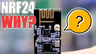
It's hard to see the connections on your picture but it appears there are 3? It may be difficult to get good results if that's the case. The hack I did just had one connection so all I had to do was solder an additional piece of wire. If you did want to try to add some wire then the total length of a 2.4 GHz full wavelength antenna should be 4.92 in. So, you would need to measure what's already existing on your PCB and subtract that from your total length of additional wire. Make sure you don't count the part that will be soldered to the existing PCB as part of your additional length. This is a crude method but if you are careful you should be able to desolder the antenna if you find it doesn't help. Good luck!
Thanks for the response Negative, there is only 1 antenna which is a PCB antenna in the upper left corner of the controller (it looks like gold leafing) I will try that, thanks again
Why did you use an 83mm antenna extension? I'm not a professional, but I know that If you want the best possible range, you want the antenna length to match the wave's frequency. According to www.qsl.net/kd4sai/antencal, If we input 2.4ghz or ruffly 2450mhz as our frequency, the same operating wave frequency as the NRF24L01, we get an antenna length of around 116mm. We can then take the calculated length and divide it by 2 to get half the wave's length (I'm not an expert, but I'm told this also works just fine).
I had to go back an check my notes for this one :) Here is what I had: The total length of a 2.4 GHz antenna should be 4.92 inches. I calculated about 1.64 inches is existing (on the PCB) so I added 3.28 inches (8.3312 cm) of Cat5e cable.


I just used this video to solder a nub of wire onto the PCB i pulled from a cheap BT speaker which I have soldered onto audio leads to add wireless sound to my old-school stereo receiver at work. It used to have an unobstructed range of maybe 5 feet, and would drop signal from 2 feet away through one layer of plywood office wall. Now it stays solid clear across the garage (about 15 ft.) and keeps playing through the plywood wall with no drops!
Well done, mate. Good video - very useful for the home tinkerer who may not have the micro-soldering equipment required by other videos on the subject!
Whenever you're making an antenna (or extension) you do NOT CUT FIRST THEN SOLDER, you always take a bit more wire than needed and SOLDER THEN CUT the wire to the correct length ... Otherwise the amount of wire overlapped onto the PCB trace (or original antenna wire) is a loss from the overall resulting length and at 2.4 GHz a little bit makes a big difference (it's even more picky at 5.8 GHz) .
+Bill Chenoweth good idea, thanks for sharing.
@@peteb9105 thanks pete for accepting Bill tip. (smart of u not to take it as personal attack :) )
@@allersvp yes, tbh reading caps makes someone think that person is mad or yelling at you
Damn, What a simple solution. Thanks bro, I was thinking replacing another expensive complex transceiver since it cannot cover the range I want.
I've done this to an ESP32 and it worked really well. I soldered a 3 pin female header between the ANT connection and ground with the remaining pin soldered to the disconnected meandered trace for additional mechanical support. I also added a liberal blob of epoxy as its pretty easy to pull those traces of the board. I just stuck a couple bits of hookup wire in the sockets as antennae. Using a straight monopole and a quasi-dipole (another monopole connected to gnd) both gave similar performance. I remember one network's RSSI had been ~ -70dBm prior to the mod and -45 afterward. As far as the NRF goes though, you're better off just buying the version with a power amp and SMA connector and screwing a rubber ducky from an old router on to it.
It work really nice with this modification. I have tested it and the signal goes better and lost packet goes lower. So this solution is great for increasing the performance.
I was literally ~30cm short of range and it helped me!
I did the same thing with a ESP8266 wifi antenna and it worked. Thank you!
I can't find any solid core cat 5 wires like yours. All I found were the ones for routers. How do I search for ones like yours?
This is totally wrong, sorry. The pcb antenna is calculated to match with the tcvr, and you just can't measure it's length! There are a lot of things like shortening factors, imedance, and other stuffs you have to calculate in. With this mod, i'm sure you unmatch the impedance, and at a higher transmit powers (like PA+LNA version) it could kill your transmitter!
If you want to do the correct way, you should disconnect the entire antenna with a cut after 2-3mm, and solder a wire antenna on. The proper size should be l=((C/F)/4)*0.96, where C is 300, F is the freq, like 2450MHz (center of the band), and 0.96 is the free air velocity factor: l=(300/2450)/4*0.96 gives you to cut 29.4mm bare wire for a quarter wave antenna.
You can read more about here:
en.wikipedia.org/wiki/Velocity_factor
en.wikipedia.org/wiki/Monopole_antenna
+Attila Wagner Thanks for sharing. I'm no expert but it worked for me. Nice to have other options like you linked to.
Hope it helps you! :)
+Attila Wagner may the little straight trace (and it's hole) under the wave one is there just for adding an external antenna ? And then, cut the pcb upside that.
If so. Does it still 29.4mm after the little hole ?
+PierreWapata If you want to use external antenna, you have to disconnect the whole pcb antenna. I recommend this mod: www.instructables.com/id/Enhanced-NRF24L01/
Attila Wagner I've seen this mod too. I may do this way. Unless i find an other with antenna like a pig-tail. I can take less space i suppose.
And thanks for the answer !!
That's a cool video. I made a breadboard adapter using wire from a cat5 cable. I soldered headers to perfboard so I could test it. Info like yours makes these modules insanely cheap. Thanks for sharing.
+3deeguy You're welcome, glad you like it.
Damn, I wish I had though to try this for my range comparison a few months ago. Oh well, I'll definitely give it a try anyway. My understanding is that these antennas are carefully crafted to work with the board they are part of... how much has this increased the range you are getting over the standard PCB only antenna?
***** I haven't done any formal testing, I have just noticed it helps with communications in my house. My theory is that the PCB antennas are fairly directional and adding on the additional wire helps get around that. For example, one of my nodes is about 45 ft away, through 7 walls and it wasn't communicating consistently. When I added the antenna it works every time. Sorry I can't be more specific that that.
+iforce2d you need to compare it like in your video
+iforce2d I watched your video where you made a transmitter using nrf24l01 modules to control your quadcopter. I want to make something similar.
The problem is I program Parallax Propellers and most activity involves Arduinos.
Transmitting data in addition to servo signals opens a lot of opportunities so it's worth the effort.
Just a thank you for uploading this vid 👍👍👍. Using this simple mod on 2 x wemos d1 minis. Now i can get the data from 2 shunts to give me the SOC etc to home assistant from within my metal shed into the house yay 😃😃. (i used some thermocouple wire for the antenna as thats all i could find, and works well - eg, no reception outside the shed, now works from inside, awsome.)
Awesome! Glad it worked out.
Peter B, you measured line to right turn, zig zag & right turn (0:50)?
Then 4.92" - above number = new mod antenna, correct?
Correct, the total length should be 4.92 in. I calculated about 1.64 inches is existing so I added 3.28 in (8.3312 cm) of Cat5/6 wire.
What about a ceramic chip antenna? Can you recommend some models?
Here is a quick video on modifying a NRF24L01 antenna to improve radio communication. I have been using it with virtually all my mysensors.org projects. It's cheap and easy so give it a try. It has been working great for me and hopefully you will get the same results.
can this be used on something like a cubesat?
Braden T You mean like those crowdfunded satellites that go to low earth orbit? If that's the case... lol no! This probably improves the NRF24L01 from 30 meters to what, 60 maybe? Not all the way to LEO.
My understanding is that there are power resistors built into this specific board that limit it’s ability to do much with an extension. I think you can solder one or two off though. Did it make a big difference for you anyway?
Thanks. Solved my problem without any fuss.
Have you noticed if the chip gets hotter? In making this mod, you will have changed the impedance of the antenna, which means your chip will be driving more current into it, and will be causing more heating. I don't know how the chip is designed - but we all have an idea what goes into them. I believe the heating will be very local - probably one or two transistors in the antenna feed, so while the entire chip may not get noticeably hotter, you could still blow the antenna feed. You might be able to measure PSU current with and without the antenna extension.
Have you done any measurements on signal strength (eg taking the receiving unit further from the transmitting unit to see at what distance it fails)?
In an application where the transmitter is used on a very low duty cycle (a few millisecs in several seconds), this may be OK. If it increases range as you say - well, nobody can argue with success. If it works, it works.
DISCLAIMER - the only thing I know about antenna design is what I remember from my tech college course 50 years ago.
Hi Mike,
I haven't noticed the chip getting hotter but to be honest I have never done any testing regarding the temp. It would be interesting to check the current draw with and without the additional antenna.
I have not done any scientific measurements on signal strength either. It all started as a simple way to see if I could increase the range of my sensors. When it worked, I was happy and moved on to making more sensors. :)
If you end up doing any tests please post back here as I'd love to hear your results.
Pete
Hi. Is it possible to modify the smartphone Bluetooth antenna. Do i need to modify the resistor and capacitor of the antenna feedline to avoid heating. I am planning to modify the smartphone Bluetooth antenna to improve its range. Thanks for the response.
Wow, didnt think it would, but definetely improved transmission for me ...
this odule does not have a PA (preamplifier) basically no amplification. Anyway it can have better reception but i am not sure about better transmittion.
Pete, how did you calculate the antenna length? A quarter wave antenna on 2.4 ghz should be about 1.1 inches long, not 4.
He did a full wave calculation no?
is that work with ESP8266
Sorry for the delay. It could. I would make sure to measure the PCB trace to get the correct length of wire you need to add. The PCB antenna may be different on the ESP8266.
I use NRF24LO1 with antena module which is 1.1km if i use bigger antena is if effect my module ?
what is the maximum range with this modification?
Great question. This was a non-scientific (and cheap mod) that has worked for me in my house. I never did any extensive (or scientific) testing. I just found it worked with sensors/radios that were in odd places throughout the house. Sorry I don't have better info.
Where can I get the cat5e wire....I did not get a supplier for the bare wire....it is available as a cable
Just cut open any network cable and you can separate the strands.
@@peteb9105 thanks
Hey Pete, thanks for all the great videos! I'm just getting into HA and your videos have been so integral for me. Bought a Vera Edge, built the serial gateway just like yours, then built the Smart Outlet just like yours as my first piece of automation. It's great but it's only working intermittently unless it's very close to the gw. The place I want to put it for now is through a couple walls and maybe 35 feet from the gw and there it gets iffy. I tried boosting the transmit to MAX in myconfig.h and re-uploaded the gw sketch but it's not much better. So thinking about trying this antennae trick but wondering if it's ok to bend the wire around inside the gang box? Have you tried that? Just wondering if the enclosure isn't hurting the effectiveness of signal and whether this antennae will still help if also enclose (and bent around) in the tight space of the gang box...
+Ben Alsop
Great, glad you're getting into mysensors. It's tons of fun! I just wish I had more time to work on projects...
Hmm. 35 ft is not that far but it depends on how many walls it has to pass through. I use the radios in this video for every project as I didn't have much luck with the amplified version. I have my gateway and nodes set to MAX unless they are very close to each other. You can definitely try to bend the antenna in the enclosure. Just make sure it doesn't come into contact with anything so it doesn't cause a short. I generally drill a hole in my enclosures to poke the wire through just to make sure this doesn't happen. I actually just added an antenna like this to one of my intermittent nodes a couple of days ago and it has been great ever since.
If it still doesn't work you could build a repeating node to relay the signal to the gateway.
+Pete B Thanks for the reply Pete. It's seems to have gotten a little better after I adjusted the position a little bit. Probably works 90% of the time now which I can live with for now. I thought about a repeater in between as well. I know I'll be doing more projects so just a matter of time before I get something in the room between the gw and this outlet. Do you have any experience with any of the pre-packaged z-wave switches (e.g. GE127...)? I was thinking of getting a few of those to increase my level of HA in the house. Do you know if those would work as a repeater in the Mysensors network? Would you add them to the Vera by the inclusion process in the Mysensors plugin or would you directly "add device" in the Vera UI? Thanks for any info!!
Ben Alsop Z-Wave and MySensors are not compatible with each other so they won't help each other boost the signal. I would be cool if they did though! If you're adding Z-Wave switches to Vera you would want to use the Vera inclusion process, not the MySenors one. Hope that makes sense and sorry for the short reply, in a hurry :)
why the hot wire is connected to ground in this antenna btw ?
We're talking about 2.4 GHz. Every wire has some inductance and capacitance. That 10mm wire to ground is short at DC, but it is an inductor at GHz frequencies.
Sir can we use copper wire as antenna wire ?
Yes, that's what I'm using. I just using one of the individual solid copper wires from a Cat5/6 Ethernet cable.
What happens if I make it longer?
It won't work as well. Antennas need to be a specific length that corresponds to the frequency of the wave.
@@peteb9105 thanks
Can you unsolder this and do a range comparison as I am thinking of doing this to a cheap multiprotocol 2.4ghz would be a good video
The calculation seems weird. You measured it already being 1.64 inches, which is about 40mm. But the internet says, 2.4 GHz should have 28 to 32mm. So this antenna is already too long. Anyway, I'll just try soldering about 20mm of wire and we'll see :)
I guess, it should also work for the smaller SMD NRF24L01 modules, right? I have a tight space in the device where I'm adding Arduino Pro Mini, so I soldered an SMD version of NRF24L01 module directly onto Arduino. It works almost fine, but sometimes it gets stuck not receiving an ACK from the receiver and sending the same message a few times in a row. So, I hope an antenna extension might help add more sensitivity to receive those ACKs.
I'm also wondering why does the PCB antenna has that other small branch and whether it can mess up the total length? It essentially makes it like having a two-wing antenna instead of a single line, so this is confusing.
there are variations to traditional half wave dipoles, like full wave dipole and 1.25 wave dipole, and i think his antenna fall into the 1.25 wave one
can i use NRF24L01 to connect to android smartphone ? i tried but it ask me the code to ensure the communication :/
+Ahmed Chtioui
I'm not sure, sorry. I use it exclusively with MySensors.org projects. You may want to check out the ESP8266. That may be easier to connect to a phone (but I have never tried it).
+Ahmed Chtioui You can't connect with phones, use bluetooth or wifi adapter for that. The ESP8266 is a good piece of hardware, but for phone connection, i suggest you to use bluetooth to serial adapter.
Thnx Attila Wagner ;)
Hello Pete
I tried as you say but I did not see any improvements in the range. Are you sure it works? And is there any special type of the cable to be used?
+Hiloliddin Jaloliddinzoda
It has definitely helped my radio communication but you may want to give this a try if you're not seeing good results. www.instructables.com/id/Enhanced-NRF24L01/
I am using cat5 wire from an Ethernet cable.
Hello again. Thanks for fast respond. Actually I tried this Link Dipole also. Maybe did not make as exact dimentions as said in thant link. I tried it already. A bit better was the range. But not perfect. 2 walls and maybe 6-7 meters apart. With normal its own antenna no signal I recieve. With dipole I recieve maybe in 1-2/20 sent signals
Hiloliddin Jaloliddinzoda
Wow, that's not good! Are you using MySensors? If so, did you set both the gateway and nodes to RF24_PA_MAX in myconfig.h?
+Pete B
Actually I only tested with codes in this link: arduino-info.wikispaces.com/Nrf24L01-2.4GHz-HowTo.
And did not do any think different other then trying antenna changes.
While I agree with Attila Wager, this shouldn't work - it totally does!
Maybe there is some impedance matching in the IC?
Thanks for the tip Pete B!
+Will Cooke
Great, glad it worked for you too! It may not be a perfect solution but I get noticeably better results.
You are measuring with a vernier caliper, not micrometer.
+Henry James Yeah, I always get the names confused for some reason. I realized shortly after I uploaded the video but it was too late. Oh well... Thanks for pointing it out.
it works man. Thanks a lot
How far do you get with this antenna? Thanks.
+Marc Paradis
I have never actually tested the range, sorry. I have a smaller house and there are times when the pcb antenna will not communicate with my gateway. When I add this antenna it has fixed the communication issues.
I have the so-called "long range" expensive version of this with the external antenna. Looking at the amplifier IC, it has a digital input to switch between TX and RX which is wired to the antenna output of the NRF24. 0 is RX and 1 is TX. Wiring a digital input to an antenna signal is plain dumb, you will loose signal strength and the digital input won't work right. So, all you need to do is cut that trace and turn the transceiver in either RX or TX-only or connect that digital input from the amplifier to the Arduino to control direction (keep in mind the auto-ACK feature of NRF24, you might need to turn that off). I am sure that once you'll do that it will work for a very long range, until then, it's just a waste of money and your solution in this video might work better and cost a lot less. Just a FYI for all of you who want long range on these things and plan on buying the expensive version. And another note: if you look at the cheaper version with the PCB trace antenna, it has a route straight to the ground plane. If you solder the additional 8cm as shown in this video cut the trace that goes to ground and you'll get much better range.
+radby Thanks for sharing.
Thanks radby, One question: Can you tell us where is the trace that goes to ground? (The one that has to be cut)
I know it breaks all the rules but I did this on an Android TV Box that has the antenna embedded on the circuit board. It's on the far side of the house compared to the router, no access to Ethernet. The TV Box was getting 3Mbs down and 3Mbs up on a 50Mbs down 5Mbs up connection, Making the antenna full wavelength the speed test went to 25Mbs down and 5Mbs up. My cell phone gets 13Mbs down and 5Mbs up sitting next to the TV Box. Closer to the router the TV Box and cell phone would always speed test at the full internet speed.
In the case of this antenna the total length from tip to feed point is 0.492" or 1/10th wavelength. I added enough wire to make the total length 4.92".
I paid 20 bucks for the box so it it blows up the wifi chip tomorrow, I'm ok with that.
+Ima ddicted awesome! I have been using this since I made the video and my radios are still working great.
Very bad solution. You need to disconnect pcb antenna.
does shorting the capacitor at the antenna point helps as well???
actually he did, if you read and watch very closely.
it's a fucken caliper not a micrometer
While understanding my question is based in a different area of use, I believe you can answer my question.
I have a drone that runs on 2.4Ghz. The controller has an integrated antenna, much like in your video, I believe it's called a PCB (printed circuit board) antenna. There are several modifications for other "wired" antennas which allow for extended range but your video is the closest thing I have come to in finding a modification to increase range with an integrated antenna.
My question is this; you mentioned something about the length of antenna (4 inches) being a requirement of sorts. Can you go into a little further detail as I would like to solder a wire to increase the range of my drone. is there a maximum length or minimum length of the wire must be to be effective?
It's hard to see the connections on your picture but it appears there are 3? It may be difficult to get good results if that's the case. The hack I did just had one connection so all I had to do was solder an additional piece of wire. If you did want to try to add some wire then the total length of a 2.4 GHz full wavelength antenna should be 4.92 in. So, you would need to measure what's already existing on your PCB and subtract that from your total length of additional wire. Make sure you don't count the part that will be soldered to the existing PCB as part of your additional length. This is a crude method but if you are careful you should be able to desolder the antenna if you find it doesn't help. Good luck!
Thanks for the response
Negative, there is only 1 antenna which is a PCB antenna in the upper left corner of the controller (it looks like gold leafing)
I will try that, thanks again
Why did you use an 83mm antenna extension? I'm not a professional, but I know that If you want the best possible range, you want the antenna length to match the wave's frequency. According to www.qsl.net/kd4sai/antencal, If we input 2.4ghz or ruffly 2450mhz as our frequency, the same operating wave frequency as the NRF24L01, we get an antenna length of around 116mm. We can then take the calculated length and divide it by 2 to get half the wave's length (I'm not an expert, but I'm told this also works just fine).
I had to go back an check my notes for this one :) Here is what I had:
The total length of a 2.4 GHz antenna should be 4.92 inches. I calculated about 1.64 inches is existing (on the PCB) so I added 3.28 inches (8.3312 cm) of Cat5e cable.
that is a caliper... not micrometer...
Thank you i Will try it for sure
Cool. Thanks!
node mcu antenna. any input anybody?
yes
cool tip! thank you! :) I want to get into these NRF24L01 soon!
#BLT-Tech
Obrigado me ajudou muito!! Funcionou !!
nice
Completely unscientific.. but works nonetheless
i don't think it will work
Thanks .i do this today and increase the range of my bluetooth 🖒
Doesn't even a single db
Ну хорошо работать точно небудет. Антенну надо без катушки подключать.
fack