I've always had trouble with electronics and they don't teach everything in the class, so I have to rely on TH-cam videos to help me out. This one definitely solved some confusions and misunderstandings! THANKS A LOT!!!
Awesome video, I didn't know that the dynamic loads caused current spikes even if the input is pure DC, although it may seem obvious, we forget such minor but important details while dealing with projects where the requirements are stringent (For ex: Instrumentation), I'd say it's a trap for beginners and hobbyists, keep making such videos, they are very helpful!
3 minutes in and I understand noise and parasitic inductance and resistance better than I ever have. Also, haven't even touched on decoupling caps yet lol. Great material here!
I always wondered why do we add both electrolytic and ceramic capacitors at the same tyme as bypass capacitors, even though the net capacitance wasn't much changed. I only thought in terms of capacitance value and not the different properties of these two different types of capacitors . But well, i got the answer now. Thank you Foolish Engineer. Your videos are really helpful, keep going...
I saw on my home stereo main board, between the tone control IC (it is TDA7442 by ST) and the audio amplifier IC (it is TDA7297, also by ST), there is elco connecting between the two +ve & the -ve placed near the audio amplifier TDA7297 IC, both on the Right input (R-IN) & the Left input (L-IN). What are such capacitors used for AC? As we know, audio is AC signal. For DC, we may understand as your explanation.
This is such a well produced and understandable video, thanks so much! I've subscribed to your channel and saved the video for future reference. 👍👍👍👍😃😃😃😃
I hope this helps and is taken in the right way. If I block you in a passageway I impede your movement. The spelling is ped but the pronunciation is peed (like pee/urinate), the e on the end signifies this modifcation from the short "eh" to long "eee" sound for the proceeding vowel. So when saying this word say it like impeedence. When you were saying impedence I kept thinking you were saying impotence :D which is something else entirely!
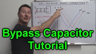
Great and concise video. Are the graphs of capacitor packages available online so you could make a rough estimate which you would need at particular frequency?
Bro thank you for the information, you explained very well. I just want to say can you just remove background sound because it interrupts your actually content.
hai, how to calculated the decoupling capacitors values and how to select capacitor value for ics how have any calculations for decoupling capacitor calculations
By doing a FFT (fast fourier transform) on an oscilloscope or any signal treatment tools you can identify the parasites frequencies. Though my answer maybe very late 😂
@@amadouabdoulayedieng8987 Thanks for your reply. And no you are not late and I want to thank you again So Some Oscilloscopes have FFT features to measure noise frequency?
The current (sinusoidal steady-state) in a capacitor is due to the resultant electric field E_net (resultant of the applied field and an opposing electric field, the fringe field). If the capacitance of the capacitor C is made large, then the fringe field does not build as fast as it would have if C were to be smaller. With a large C, the charge sprays on the plates do not result in developing a large voltage in a given interval of time as evident from the capacitor voltage-charge relation Q = CV. The fringe field is smaller and the net field consequently is greater. Therefore, at a fixed frequency, the current increases as the size of the capacitor is increased. The current also increases as the frequency is increased. So, we say it passes higher frequencies of applied voltage. If the frequency is made smaller, the fringe field builds very rapidly and in the limit when it is dc, it blocks the applied voltage. If a resistor R is connected to the capacitor then the resistor limited current is not enough to dump charge fast enough at such high frequencies and of sufficient quantity to produce any significant opposing fringe field. Therefore, for a given RC combination the output voltage picked across the resistor is able to reproduce the input signal with less attenuation. We say that the capacitor bypasses the high frequencies …..in reality, the electric field of the input voltage passes “through” the capacitor with almost no opposition. This makes the capacitor useful as a coupling capacitor for ac signals in amplifiers and also as an emitter bypass capacitor in transistors that will afford larger output swings by reducing the amount of ac signal feedback without affecting stabilising dc feedback. It is not possible in this post to discuss in more detail current in capacitor circuits and capacitive reactance. Electrostatics and circuits belong to one science not two. To learn the operation of circuits, Current and the conduction process, resistors and how discussing these topics makes it easier to understand the principle of superposition of potential which is a direct consequence of the principle of superposition applied to electric fields, watch these two videos i. th-cam.com/video/TTtt28b1dYo/w-d-xo.html and ii. th-cam.com/video/8BQM_xw2Rfo/w-d-xo.html The last frame of video 1 contains in the References articles and textbooks which discuss the unified approach. Sections 3.1 to 3.3 in Chapter 3 of textbook 4 discuss the operation of the RC coupling circuit with sequential diagrams using the unified approach. Also, Section 3.6 in Chapter 3 of textbook 4 discusses the operation of the bypass capacitor tied across the emitter resistor using the unified approach with the help of sequential diagrams in a transistorised common-emitter amplifier.
I have a question about boostrap capacitor on the egs002 module a valve of 22pf 25 v rating is use but when I measure the voltage from the high side the voltage is 230 volt the same as the h bridge switching voltage how comes the gate voltage is the same and igbt capacitor have rating of 30 volt max but the boostrap capacitor charge up 230 volt with a 25 volt valve capacitor and the circuit don’t blow up explain
@@FoolishEngineer People like you probably dont realise that when you impart knowledge and make things that people like me find difficult you are empowering us. We think more of ourselves and strive to become more knowledgeable and better ourselves. Then we in turn do the same to those in need of our help. You sir are part of my journey and I thank you for being the person you are that makes life better for so many. May you be loved all your days.
Nice presentation, quick question, you highlighted that for the low-frequency noise a "large electrolyte cap can be use" also a large ceramic capacitor (like 10µF) can be used as well right? thanks
@@FoolishEngineer regarding the frequency of noise, how to be determined? In the case of RF power amplifier? Is it second and third harmonic freqiencies?
Thank you so much for this video, great animations. How can I calculate the value of the decoupling capacitor? Does it need to be in resonance with the noise frequency?
You will have to measure the frequency of the noise and accordingly, you will have to select a capacitor which has very low ESR at that particular frequency. But this is a very tedious process, you can read the datasheet of the component which you are using they might have suggested the Decaps for their chip


I've always had trouble with electronics and they don't teach everything in the class, so I have to rely on TH-cam videos to help me out.
This one definitely solved some confusions and misunderstandings!
THANKS A LOT!!!
Happy to help!
I forgot a lot of this stuff from my undergrad. Thanks for such a great refresher!
You're so welcome!
Awesome video, I didn't know that the dynamic loads caused current spikes even if the input is pure DC, although it may seem obvious, we forget such minor but important details while dealing with projects where the requirements are stringent (For ex: Instrumentation), I'd say it's a trap for beginners and hobbyists, keep making such videos, they are very helpful!
Thank you so much, dude!!
Wau - I love the clear knock on knowledge - you serve it with elegance and perfection. Thanks.
My pleasure!
the animations really helped. thanks
Glad you liked it!!
Please tell how your making the animation
Thank you for such an informative animated video. Most of my long-standing doubts have been solved today.
Thank you so much, Glad you liked it!!
Cristal clear! Thank you for this reminder. I've check the datasheet for a "74HCTxxx" and had to see your video for good explanation and reminder !
Glad it helped!
Magnificent explanation, you earned my subscription and hands up, I will continue watching your videos, greetings from my beloved Venezuela.
Welcome aboard!
One of the best video I have seen.
You're great at explaining things, thank you!
3 minutes in and I understand noise and parasitic inductance and resistance better than I ever have.
Also, haven't even touched on decoupling caps yet lol. Great material here!
Cool!! You got this!
The most well-explained video on decoupling capacitors! excellent work!
Glad you enjoyed it!
This is an amazing video! Thank you so much for sharing such an educational content. Much appreciated!
Excellent video and explanation of Decoupling capacitors and it's use , simply excellent
I am so glad this was recommended to me. Very helpful thanks
Glad it was helpful!
Thank you for this amazing video, really brought up cases where this is needed, how it occurs and how to deal with it.
Thank you so much for watching!! Please don't forget to subscribe to our channel
I always wondered why do we add both electrolytic and ceramic capacitors at the same tyme as bypass capacitors, even though the net capacitance wasn't much changed.
I only thought in terms of capacitance value and not the different properties of these two different types of capacitors .
But well, i got the answer now. Thank you Foolish Engineer. Your videos are really helpful, keep going...
Thank you so much! Please show support to my video with Super thanks and don't forget to subscribe to our channel
Thank you alot for that lesson it has helped me a lot.
If i have an Amplifier of 2000W, and how can i increase to 4000W?
I saw on my home stereo main board, between the tone control IC (it is TDA7442 by ST) and the audio amplifier IC (it is TDA7297, also by ST), there is elco connecting between the two +ve & the -ve placed near the audio amplifier TDA7297 IC, both on the Right input (R-IN) & the Left input (L-IN). What are such capacitors used for AC? As we know, audio is AC signal. For DC, we may understand as your explanation.
This is such a well produced and understandable video, thanks so much! I've subscribed to your channel and saved the video for future reference. 👍👍👍👍😃😃😃😃
Thank you so much for your very clear and useful information. you explained in a very simple way to understand everyone.
Thank you so much! Please show support to my video with Super thanks and don't forget to subscribe to our channel
Thanks a lot for the explanation, probably the best on this topic ❤
This was amazing! I learned a lot from it in such a short amount of time
Thank you so much, Glad you liked it!!
Do you need an occiliscope to do this stuff or can you do by ear?
Excellent lecture.
I bet indian youtubers already taught me more than all my high school professors. Really great video!
Thank you so much for watching!! Please don't forget to subscribe to our channel
Nice video sir, some thing I forgot now I remember and clear it thankyou so much
0:59 "If those noise is present they will have very difficulty while working."
Words to live by...
Great job my man, you learned me sumpin new!
I am not a legend😅, Thank you so much for watching!! Please don't forget to subscribe to our channel
your videos are one of the best .
i really appreciate it sir
Thank you so much! Please show support to my video with Super thanks and don't forget to subscribe to our channel
Brilliant!! Thank you for a clear and concise explanation. Cleared up many of the doubts i had regarding capacitors.
Very well explained!
Thank you so much! Please show support to my video with Super thanks and don't forget to subscribe to our channel
Extremly informative and helpful.
Thank you so much! Please show support to my video with Super thanks and don't forget to subscribe to our channel
Very good explanation. 👍🏻
Excellent explanations! Though I found the background music distracting. Thanks for the presentation.
Great video with great explanation.
Thanks you so much
You are welcome!
Precise and very well explained thankyouu
Thank you so much for watching!! Please don't forget to subscribe to our channel
Thank you, sir. Great explaination
You are welcome
covered everything very nicely. great job!
Thank you so much! Please show support to my video with Super thanks and don't forget to subscribe to our channel
Great content - thank you!
Glad it was helpful!
Thanks dude, you made it really simple to understand😊
Thank you so much! Please show support to my video with Super thanks and don't forget to subscribe to our channel
Awesome video, very well explained!
Glad you liked it!
Your channel is the best
Thank you so much! Please show support to my video with Super thanks.
I hope this helps and is taken in the right way. If I block you in a passageway I impede your movement. The spelling is ped but the pronunciation is peed (like pee/urinate), the e on the end signifies this modifcation from the short "eh" to long "eee" sound for the proceeding vowel. So when saying this word say it like impeedence. When you were saying impedence I kept thinking you were saying impotence :D which is something else entirely!
😅😅
Great and concise video. Are the graphs of capacitor packages available online so you could make a rough estimate which you would need at particular frequency?
You can get this graph in the datasheet of any capacitors before selecting.
this is amazing. thanks for the explanation
Nice and easy to understand
Thank you so much! Please show support to my video with Super thanks and don't forget to subscribe to our channel
How do we choose package of the capacitor in MLCC ?
Bro thank you for the information, you explained very well. I just want to say can you just remove background sound because it interrupts your actually content.
Sorry for that
hai, how to calculated the decoupling capacitors values and how to select capacitor value for ics how have any calculations for decoupling capacitor calculations
Thank you very much.
Thank you so much! Please show support to my video with Super thanks.
A superb explanation.
I am so glad you liked it
This video is really helpful and good to understand basics that how decoupling capacitor works..👍👍..good work keep it up🙏
Thank you so much, Glad you liked it!!
Thank you for the very informative video.
Thank you so much for watching!! Please don't forget to subscribe to our channel
esr does not change resonance frequency fr where the impedence is equal to esr. the curves must not show dephasing around fr
excellent explanation.
Thank you so much for watching!! Please subscribe to our channel
Great animations and presentation
Thank you so much, glad you liked it!!
Great Explanation.
at 7:52 how do i know or how do i measure the frequency of noise?
By doing a FFT (fast fourier transform) on an oscilloscope or any signal treatment tools you can identify the parasites frequencies.
Though my answer maybe very late 😂
@@amadouabdoulayedieng8987 Thanks for your reply. And no you are not late and I want to thank you again
So Some Oscilloscopes have FFT features to measure noise frequency?
@@mohammadk9144 Exactly
@@amadouabdoulayedieng8987 is it possible to measure it without FFT feature? or thats gonna take a while?
easy to understand, thank you.
What is considered low and high frequency?
Great video with great explanation.
Thanks a lot
Most welcome!
Great video 💪💪
How does one determine the noise frequencies, so that the proper bypass capacitance values can be calculated?
It was of great help..amazing video..thank you loads ❤💯💯
Thank you so much, Glad you liked it!!
What is the difference between nF and nH
Very excellent explanation thank you!
You're very welcome!
nice explaition video, bro in which tool you make thes videos?
Thank you so much for watching!! Please don't forget to subscribe to our channel.
Adobe after effects
great video... thanks!
You're welcome!
The current (sinusoidal steady-state) in a capacitor is due to the resultant electric field E_net (resultant of the applied field and an opposing electric field, the fringe field). If the capacitance of the capacitor C is made large, then the fringe field does not build as fast as it would have if C were to be smaller. With a large C, the charge sprays on the plates do not result in developing a large voltage in a given interval of time as evident from the capacitor voltage-charge relation Q = CV.
The fringe field is smaller and the net field consequently is greater. Therefore, at a fixed frequency, the current increases as the size of the capacitor is increased. The current also increases as the frequency is increased. So, we say it passes higher frequencies of applied voltage.
If the frequency is made smaller, the fringe field builds very rapidly and in the limit when it is dc, it blocks the applied voltage.
If a resistor R is connected to the capacitor then the resistor limited current is not enough to dump charge fast enough at such high frequencies and of sufficient quantity to produce any significant opposing fringe field.
Therefore, for a given RC combination the output voltage picked across the resistor is able to reproduce the input signal with less attenuation. We say that the capacitor bypasses the high frequencies …..in reality, the electric field of the input voltage passes “through” the capacitor with almost no opposition.
This makes the capacitor useful as a coupling capacitor for ac signals in amplifiers and also as an emitter bypass capacitor in transistors that will afford larger output swings by reducing the amount of ac signal feedback without affecting stabilising dc feedback.
It is not possible in this post to discuss in more detail current in capacitor circuits and capacitive reactance.
Electrostatics and circuits belong to one science not two. To learn the operation of circuits, Current and the conduction process, resistors and how discussing these topics makes it easier to understand the principle of superposition of potential which is a direct consequence of the principle of superposition applied to electric fields,
watch these two videos
i. th-cam.com/video/TTtt28b1dYo/w-d-xo.html and
ii. th-cam.com/video/8BQM_xw2Rfo/w-d-xo.html
The last frame of video 1 contains in the References articles and textbooks which discuss the unified approach.
Sections 3.1 to 3.3 in Chapter 3 of textbook 4 discuss the operation of the RC coupling circuit with sequential diagrams using the unified approach.
Also, Section 3.6 in Chapter 3 of textbook 4 discusses the operation of the bypass capacitor tied across the emitter resistor using the unified approach with the help of sequential diagrams in a transistorised common-emitter amplifier.
Thanks and superb!
Thank you so much for watching!! Please don't forget to subscribe to our channel
We have done one application in general pcb .. but when we built pcb.. creating lots of problems with decoupling capacitors
Very useful, Many Many Thanks :)
Thank you so much for watching!!
I have a question about boostrap capacitor on the egs002 module a valve of 22pf 25 v rating is use but when I measure the voltage from the high side the voltage is 230 volt the same as the h bridge switching voltage how comes the gate voltage is the same and igbt capacitor have rating of 30 volt max but the boostrap capacitor charge up 230 volt with a 25 volt valve capacitor and the circuit don’t blow up explain
TOO GOOD! keep doing what you are doing cuz its incredible!
Thank you! Will do!
What do you use for animation? Great video
After Effects. Thank you so much for watching!!
Brilliant. Thank you
Thank you so much for watching, glad you liked it!!
@@FoolishEngineer People like you probably dont realise that when you impart knowledge and make things that people like me find difficult you are empowering us. We think more of ourselves and strive to become more knowledgeable and better ourselves. Then we in turn do the same to those in need of our help.
You sir are part of my journey and I thank you for being the person you are that makes life better for so many. May you be loved all your days.
Nice presentation, quick question, you highlighted that for the low-frequency noise a "large electrolyte cap can be use" also a large ceramic capacitor (like 10µF) can be used as well right? thanks
Yes
Regarding the caps selection, How to determine the frequency of noise in the circuit? And how much this lower impedance should be (specific value)?
there is no specific value for the ESR of the Cap, it changes as per the frequency.
@@FoolishEngineer regarding the frequency of noise, how to be determined? In the case of RF power amplifier? Is it second and third harmonic freqiencies?
Thank you so much for this video, great animations. How can I calculate the value of the decoupling capacitor? Does it need to be in resonance with the noise frequency?
You will have to measure the frequency of the noise and accordingly, you will have to select a capacitor which has very low ESR at that particular frequency.
But this is a very tedious process, you can read the datasheet of the component which you are using they might have suggested the Decaps for their chip
@@FoolishEngineer perfect, thank you
how to spot decoupling capacitors on PCB without schematics ?
Great vid; Thanks!!
Thank you so much for watching!! Please don't forget to subscribe to our channel
Good job i understand it now!
Thank you
Awesome video!! Thank you
Thank you so much, Glad you liked it!!
thanks, learned something today.
Glad to hear it!
Thanks for making such videos
It's my pleasure
Great explanation, Thanks
Glad it was helpful!
Sir how to calculate decoupling capacitor for 2khz to 150khz
Excellent video!
Glad you liked it!
Excellent teaching ... Thank you for the video❤️👍🙏
You are very welcome! Glad you liked it!
awesome explanation...really needed that...thanks
Glad it was helpful!
My university lecturers should learn from you
very informative
Thank you so much for watching, please dont forget top subscribe to my channel!!!
Due to this animations explanation get easier
Thank you so much for watching!! Please don't forget to subscribe to our channel
Bahot achha bro.
thank you so much!
Good video !
Magnificent video
Thank you very much!
Thank you for this!
Thank you so much, Glad you liked it!!
thanks
Thank you so much, Glad you liked it!!
Excellent explanation. Keep up the good work. So I can identify which are bypass capacitors if they are placed parallel to the IC, correct?
Yes. Thank you so much, Glad you liked it!!
What effects do we observe when very large decoupling capacitor is connected in our circuit ?