Your channel is absolutely amazing for people just getting started out with electronics.... there's so many youtube tutorials that show how to do things, but dont show the thought process behind it like you do. And each of your videos just get better and better 😊 Thanks so much for all you do
I have been working as an electronics engineer and designer for 25 years. And I love your videos. I wish I had seen them back at the university. Thank you for this channel.
Few issues also from the manufacturing process standpoint (I have worked as an AOI and ATG technician for some time and saw all kinds of weird stuff): - clearances are critical not only because of electronical reasons, but also in the manufacturing process; especially together with thin traces. Most of the PCBs are etched nowadays and that is a chemical process. The etchant will have trouble reaching all through the copper layer in such a narrow area (it's like cleaning the bottom of a narrow glass with a sponge), so the pcbs may end up with either multiple contacts or broken (even "washed away") traces. This is especially critical when working with thicker copper layers. Usually manufacturer won't complain about it back; sometimes they will correct the design in prep process (change trace widths or even move the traces), which can influence the circuit performance, sometimes he will try his luck and count on some production to be thrown away; he probably won't supply you faulty PCBs, but you could end up with suboptimal PCBs (and most of us don't have the needed equipment to verify that) - the same goes for the trace width; try to stay well over manufacturers advertised width - this is advertising; it is possible in the production in optimal conditions (with fresh etchant solution, freshly cleaned production lines and for the well paying customers); I suspect in most of the cases the manufacturer just copies the specs from the machinery documentation. Thin traces are prone to fail in all stages of production. I have seen quite some cases, when copper "threads" got unstuck from FR4 substrate (got "underetched") - such PCB could go perfectly thorugh AOI and ATG, and even work for some time, but then (seemingly inexpliciably) fail. - "acid traps" - modern manufacturing techniques helped in diminishing the effects of acid traps in PCB designs, but in some cases you can still run into trouble and it's not worthy; most of the acid traps are also clearance violations anyway (from the manufacturing point of view) - "copper writing" - I finish with the thing, which used to annoy me the most: making texts on PCBs in copper (instead of silkscreen)(especially for small letters). It is tempting I guess, but silkscreen is there for a reason. If I simplyfy, "copper writing" are all above mentioned mistakes combined: a lot of too low clearances, possibly quite a lot of "traces" at marginal width and a collection of perfect acid traps - if you really have to do it, make it in "negative" - copper background and letters in substrate (etched through). This all depends very much on font and size used, but still: letters are made to be printed, not etched.
Great info. CAD software gives the option for making text or logos in copper (as if it's just an alternative to silkscreen) and I imagine many users going "hey that'd be super cool to do that" without knowing the drawbacks.
Is it beneficial to include a copper pour where possible, for the purpose of reducing the amount of etching fluid used? Or is that a non-issue from a manufacturing perspective?
You talked some rare to find golden advices about PCB design. I wish I could make every new PCB designer watch this video. I have one thing in my mind though: If you place via so close to pad, there will be no solder mask barrier between the pad and the via. The via will steal solder from the pad. Isn't this a problem? One other thing: If you "tent" your vias (cover it with solder mask) some manufacturers can perfectly print text on the via. Some still fail though (e.g.; JLCPCB still can't perfectly print text on tented via).
@Phil's Lab / Hi Phil, first and foremost: Great videos! Thank you very much ! Please don't stop making them ! To my question: Could you comment about your choice not to have any copper pours on the front layer ? This is something I am very eager to know!
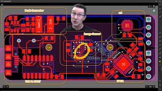
Thank you very much! I think there are a lot of differing opinions on the subject of 'to copper pour or not'. Rick Hartley says pretty much always use copper pours, Eric Bogatin says it'll usually bring problems to do so, Robert Feranec has said he typically doesn't do copper pours on signal layers. In my eyes, I always ask myself - what am I trying to achieve with copper pours on signal layers? To me the benefits of doing so (if there are even any) vs the 'annoyances' it brings with it don't match. You will need to using quite a number of stitching vias, you need to pull back the copper from controlled impedance traces, etc., etc. So given that there don't seem to be many substantial benefits, I don't use them anymore. Also I think it looks cooler this way haha.
Thanks, Phil! Looking forward to your course :D Robert Feranec uploaded a video interview with Rick Hartley. Any time Rick is on, my eyes are glued to the screen haha always have something more to learn from him, Robert, you, and many more. Keep on going!!
Hi phil😊 Thank you so much that was amazing Is there a problem if i put the via exactly on the SMD pad ? And is there a problem if i use that in a signal path ( a couple of 10 KHz)
Phil, I'm interested to learn about how a PCB heated print bed for 3D printers is made, how they make them dual voltage etc. Are there any resources you can point to for figuring this out? Would you consider making a video about designing a custom PCB heated 3D printer bed?
Hey Collin, I'm afraid I've never worked on anything to do with electronics in 3D printers - but I believe there must be quite a few resources online for that kinda thing. Doesn't seem like it would be too complicated to make if all that is required is some form of temperature feedback and a way of heating the bed.
@@PhilsLab It's literally a long trace with a calculated resistance which is a direct short between +/- rails. You calculate the desired resistance and length/width of your traces and desired max temp. www.4pcb.com/trace-width-calculator.html Having never designed ANY PCB through to completion, I was looking for tips on how to size the trace to match the length and resistance in PCB design software and run calculations there to make sure your PCB matches the figures you get from the calculator. Something to do with impedance calculation in your EDA maybe?
I love the discussion about not splitting the ground plane. One thing to watch our for is ribbon harness connectors in the middle of a PCB can inadvertently create a mote in a ground plane. One thing I think is really important is connector placement. Besides not locating a ribbon cable in the middle of a densely wired PCB, try to locate all cable connectors along the same edge of a PCB if possible. Currents in the ground plane can cause radiation out the cable shields. Get ready to add ferrites to your cables if you are unable to follow this rule.
With all those vias I imagine the topic of avoiding ground loops must then come more into the forefront of the picture, especially when it comes to analog circuitry. I hope this topic is at the very least touched on in further ground plane (or ground layer) discussions as its an exceptionally easy trap to fall for.
i think you confuse something... one ground layer with via`s isnt producing groundloops... a ground loop will just form if you actually have a ground plane with 2 vias and on another layer the two vias connect to eachother which isnt the case here (atleast for the most part)
How did you determine the via spacing around the edge of the board? How did you determine the via spacing between the analog and digital sections? Why did you put vias around the board and the "partition" between analog and digital?
for 50 ohm impedance , how are you deciding which frequency to base your measurement on? for instance, in your example you have 500mhz. are you assuming your signal trace could go up to 500mhz? or is this calculated based on each signal application?
50 Ohms are 50Ohms at any frequency. I would suggest you take a theory class on complex electrical impedance and four-poles first before attempting to troubleshoot RF problems with complex impedance.
Hi Phil! I recently came up with your channel. It is excellent. I would like to know: What are the dots separing the power planes? vias? is there a reason for you to place many vias between the different power planes? Thanks !!
Hi as you said we have to good spacing between traces it's a question for me if i have good space between my traces but i fill this space with ground plane can make crosstalk or noise?????
Thank you, Marc! I typically use only one or two sizes of vias per board. To minimise inductance you want small vias (I typically go for 0.3mm drill, 0.6mm diamter). You can also then use a calculator if you need to push a lot of current through vias. Larger vias will of course be able to handle more current - or put a larger number of vias in parallel.
5:49, I noticed that you place vias crossing into the "courtyard" boundary of the components. I didn't know it was OK to do that! Some boards even have courtyards printed on the silkscreen. I like the idea of close vias but if we do that, then we also need to make sure the courtyards aren't on the silkscreen, right?
Hi Adin ... The footprints can be added during the schematic phase . Right click and edit the part. You will find a "footprint" option . Then select a footprint from the list of parts , ie 0805 LED (under LED SMD) . Once you do that the 3D render option will add the part based off your selection ... I hope that helps . :)
Thanks for the vid. I'm actually confused about the crystal oscillator placement and via's around 8:50 in the video, so I have a question about it. Most vendors explain that crystal placement should be as close to the IC component as possible and have a few ground via's at certain positions. You could have definitely moved it much closer, but then you wouldn't have been able to put the nice looking ground square around it to protect the component from interference. You could have also put more ground via's around, or even between the traces - but apparently chose not to. Should I interpret this as "the signal integrity around the oscillator is more important than the signal integrity of the traces the transfer the signal"? Could you explain this design choice a bit more please?
Hi thanks for the video, I was wondering how would you go about crossing signals between different voltage power planes for example if I need a signal to cross from a 3.3V to 5V power plane how is that achieved?
There are no signal traces on power planes. Period. End of message. Whenever you disrupt a power plane with a signal trace you are shooting yourself in both feet. If you need more routing area, add a few more routing layers, instead.
@Phil's Lab Hi, I am quite new to PCB design. I want to add a female 4 pin header to my board so that I can connect another part later. But I want to place them at 180° (parallel to the board) and not at 90° so that I can connect from the sides and not from the top. How do I do this? Thank you in advance for your help.
Are you familiar with testing by injecting frequency and voltage, to measure isolation? What are the basic hardware tools or methods needed to check our PCB designs for isolation and cross coupling, when they come back?
A network analyzer. You can get useful ones for a couple hundred bucks on Amazon these days, even though I would spend $10-20k on a professional one if I had an actual engineering requirement. What I would question first, though, are your requirements. What are you trying to achieve with all this testing? If you want to know the bit error rate on some high speed links, then just measure the bit error rate and it is is small enough you are done. There is absolutely no need to measure RF parameters on a board that works.
Is it ever beneficial to have a track width that is bigger than the pads that it is going to for a load net? For example, a point to point track between a LDO regulator and a QFN MCU pin, would it ever be beneficial to use a track width that is bigger than the QFN pin?
Yes, for example for QFN switching regulator ICs, I'll start with the trace width of a pad and then quickly widen it out to make sure it can handle the current (for example).
@@PhilsLab in these cases (i see a lot of people do it) its hard for me to understand to widen the traces after they have been small... isnt the small part of the trace still the main current limiting factor and the thicker part of the trace afterwards isnt changing this? the only benefit i see is that if traces warm up then it might be beneficial to just have a small thin part of a trace (tho usually i would say the thin part of the trace has to be wide enough to still carry enough current without heating up to much.... so the thickening of traces after they have been small seems kinda pointless)
maybe this is mainly just to reduce resistance over the whole trace instead of a current factor? and sort of a perfectionist thing since i imagine the pcbs with consistent trace sizes would just work fine
Damn I wish Altium had those calculators in it, for the price you pay for it. I like Altium because the graphics appears smoother and not as harsh as the others. Anyway my main issue is the heat-sinking pads hope you put that in the course.
Could you talk about bluetooth design? Chips like rn4871 have very low power which makes necessarry to design your own antenna, the design of a case is also important
@@PhilsLab thank you! I have been facing problems with rf modules once I put them on cases. (I design super compact products which require to be as small as posible and sometimes certain antenna designs are not possible)
Kicad has also a built-in calculator for some trace properties, but not as many as Saturn PCB‘s. What use has the structure around the edges of your pcb?
Yeah, Kicad's calculator is definitely easier/quicker to use. I use the grounded gold-plated, copper edge on the PCB for a quick place to attach an oscilloscope ground probe to.
I followed your advice and downloaded the Saturn tool. I think it's in Chinese; I can't figure out most of it.
3 ปีที่แล้ว
Saturn PCB Design Toolkit looks great - unfortunately, it is available only for Windows (I'm a macOS user). Do you have any recommendations for a similar web-based toolkit or a mac app?
Hi Phil, how would you run a signal trace from an analog section to a digital section? For example, lets say you have an analog signal that goes to a voltage set pin of a dcdc switching converter, how can you run it across both section and maintain signal integrity?
Good stuff. I watched the Rick Hartley video too and learned a lot from it. I never even considered signal return paths before that! How important do you think track spacing is if you have an uninterrupted ground plane on an adjacent layer? I have been working on some boards which are quite constrained for space but have a lot of digital signals so I don't have room to spread them out. (pcb is here if you want to see what I mean imgur.com/a/63cPk7v )
Thank you, Matt! The Rick Hartley video is great. Track spacing is still important, even if you have a close ground plane underneath. In some situations, as you say, there just isn't enough space to get the clearance and one has to hope that it won't be a problem. Just try and maximise the clearances you can get!
I offer design services through my website (philsal.co.uk), however I am quite busy at the moment so need my schedule to clear up a bit before I can take on new work!


![ร้อยพ่อพันแม่ - WanMai [Official MV]](http://i.ytimg.com/vi/XY2pNYASEbg/mqdefault.jpg)


holy, im in the beginning of my first “real” pcb project and you have no idea how useful your videos are!!!
Thank you, Matheus! Very glad to hear that the videos have been helpful.
Every video you make is massively useful.
Thank you very much!
SATURN looks like a veeery useful tool for a noobie professional EE like myself. Thank you so much for your content.
Just down loaded it, a better tool than what's on KiCad.
Thank you, Edgar! Yeah, it's a pretty nifty tool :)
Your channel is absolutely amazing for people just getting started out with electronics.... there's so many youtube tutorials that show how to do things, but dont show the thought process behind it like you do. And each of your videos just get better and better 😊 Thanks so much for all you do
Thank you very much for your kind words! My pleasure, I hope to keep more of them coming :)
You're on a roll with these PCB videos. I just need to follow through with your advice
Thank you! I hope this helps :)
I have been working as an electronics engineer and designer for 25 years. And I love your videos. I wish I had seen them back at the university. Thank you for this channel.
Thank you so much, very glad to hear you like the videos!
Few issues also from the manufacturing process standpoint (I have worked as an AOI and ATG technician for some time and saw all kinds of weird stuff):
- clearances are critical not only because of electronical reasons, but also in the manufacturing process; especially together with thin traces. Most of the PCBs are etched nowadays and that is a chemical process. The etchant will have trouble reaching all through the copper layer in such a narrow area (it's like cleaning the bottom of a narrow glass with a sponge), so the pcbs may end up with either multiple contacts or broken (even "washed away") traces. This is especially critical when working with thicker copper layers. Usually manufacturer won't complain about it back; sometimes they will correct the design in prep process (change trace widths or even move the traces), which can influence the circuit performance, sometimes he will try his luck and count on some production to be thrown away; he probably won't supply you faulty PCBs, but you could end up with suboptimal PCBs (and most of us don't have the needed equipment to verify that)
- the same goes for the trace width; try to stay well over manufacturers advertised width - this is advertising; it is possible in the production in optimal conditions (with fresh etchant solution, freshly cleaned production lines and for the well paying customers); I suspect in most of the cases the manufacturer just copies the specs from the machinery documentation. Thin traces are prone to fail in all stages of production. I have seen quite some cases, when copper "threads" got unstuck from FR4 substrate (got "underetched") - such PCB could go perfectly thorugh AOI and ATG, and even work for some time, but then (seemingly inexpliciably) fail.
- "acid traps" - modern manufacturing techniques helped in diminishing the effects of acid traps in PCB designs, but in some cases you can still run into trouble and it's not worthy; most of the acid traps are also clearance violations anyway (from the manufacturing point of view)
- "copper writing" - I finish with the thing, which used to annoy me the most: making texts on PCBs in copper (instead of silkscreen)(especially for small letters). It is tempting I guess, but silkscreen is there for a reason. If I simplyfy, "copper writing" are all above mentioned mistakes combined: a lot of too low clearances, possibly quite a lot of "traces" at marginal width and a collection of perfect acid traps - if you really have to do it, make it in "negative" - copper background and letters in substrate (etched through). This all depends very much on font and size used, but still: letters are made to be printed, not etched.
Super. Thanks for your input 💯💯
Great info. CAD software gives the option for making text or logos in copper (as if it's just an alternative to silkscreen) and I imagine many users going "hey that'd be super cool to do that" without knowing the drawbacks.
Is it beneficial to include a copper pour where possible, for the purpose of reducing the amount of etching fluid used? Or is that a non-issue from a manufacturing perspective?
hey we are eargerly waiting for the course your promised.
Remember the whole thing takes a very long time :) All great things are worth the wait
Hey Paul, Course will come out soon - as Søren said it does take a bit of time to make. But will let you know when it's ready :)
@@PhilsLab thanks! no worries take your time.
@@PhilsLab a pcb for an easy and noob arduino nano project would be awesome, like powering some beast motor or something :$
is the course available?
THANK YOU! Rick Hartley lecture is amazing
Thank you, glad you liked the Rick Hartley lecture as well!
Awesome little video, looking forward to the course!
Thank you, glad to hear that! :)
You talked some rare to find golden advices about PCB design. I wish I could make every new PCB designer watch this video.
I have one thing in my mind though: If you place via so close to pad, there will be no solder mask barrier between the pad and the via. The via will steal solder from the pad. Isn't this a problem?
One other thing: If you "tent" your vias (cover it with solder mask) some manufacturers can perfectly print text on the via. Some still fail though (e.g.; JLCPCB still can't perfectly print text on tented via).
Wow, great introduction.
Great tips
Thanks for sharing your knowledge to all of us 👍😊
Thank you for watching, Asger!
OMG silkscreens are my JAM
@Phil's Lab / Hi Phil, first and foremost: Great videos! Thank you very much ! Please don't stop making them !
To my question: Could you comment about your choice not to have any copper pours on the front layer ? This is something I am very eager to know!
Thank you very much!
I think there are a lot of differing opinions on the subject of 'to copper pour or not'. Rick Hartley says pretty much always use copper pours, Eric Bogatin says it'll usually bring problems to do so, Robert Feranec has said he typically doesn't do copper pours on signal layers. In my eyes, I always ask myself - what am I trying to achieve with copper pours on signal layers? To me the benefits of doing so (if there are even any) vs the 'annoyances' it brings with it don't match. You will need to using quite a number of stitching vias, you need to pull back the copper from controlled impedance traces, etc., etc. So given that there don't seem to be many substantial benefits, I don't use them anymore. Also I think it looks cooler this way haha.
Thanks, Phil! Looking forward to your course :D Robert Feranec uploaded a video interview with Rick Hartley. Any time Rick is on, my eyes are glued to the screen haha always have something more to learn from him, Robert, you, and many more. Keep on going!!
Thank you, Bradley! Yes, I do exactly the same - anytime there's anything new from Rick I stop everything I'm doing haha and won't stop watching him.
I'd love a tutorial on just how to route things neatly, without needing a ton of layers and all. I'm really bad at routing things!
Hi phil😊
Thank you so much that was amazing
Is there a problem if i put the via exactly on the SMD pad ?
And is there a problem if i use that in a signal path ( a couple of 10 KHz)
Amazing series of videos ♥️♥️♥️
Phil, I'm interested to learn about how a PCB heated print bed for 3D printers is made, how they make them dual voltage etc. Are there any resources you can point to for figuring this out? Would you consider making a video about designing a custom PCB heated 3D printer bed?
Hey Collin, I'm afraid I've never worked on anything to do with electronics in 3D printers - but I believe there must be quite a few resources online for that kinda thing. Doesn't seem like it would be too complicated to make if all that is required is some form of temperature feedback and a way of heating the bed.
@@PhilsLab It's literally a long trace with a calculated resistance which is a direct short between +/- rails. You calculate the desired resistance and length/width of your traces and desired max temp. www.4pcb.com/trace-width-calculator.html
Having never designed ANY PCB through to completion, I was looking for tips on how to size the trace to match the length and resistance in PCB design software and run calculations there to make sure your PCB matches the figures you get from the calculator. Something to do with impedance calculation in your EDA maybe?
Excellent videos man. Really informative and that excellent video suggested on ground. A real eye opener that one.
Thank you very much, Nitin!
Watched RHartley's video ... great stuff!
I love the discussion about not splitting the ground plane. One thing to watch our for is ribbon harness connectors in the middle of a PCB can inadvertently create a mote in a ground plane.
One thing I think is really important is connector placement. Besides not locating a ribbon cable in the middle of a densely wired PCB, try to locate all cable connectors along the same edge of a PCB if possible. Currents in the ground plane can cause radiation out the cable shields. Get ready to add ferrites to your cables if you are unable to follow this rule.
Wonderful Tool, thanks for showing
Placing via really close to the pad can create soldering issue as the heat is absorbed by the via to the inner planes
Great. Thanks a lot ❤
Looking forward to the tutorial...cheers
Awesome, thanks Andy!
this was a great video. Thanks, Phil.
Very glad to hear that, thank you, Michael!
Could you tell us how you did the exposed copper fence around the PCB?
With all those vias I imagine the topic of avoiding ground loops must then come more into the forefront of the picture, especially when it comes to analog circuitry. I hope this topic is at the very least touched on in further ground plane (or ground layer) discussions as its an exceptionally easy trap to fall for.
i think you confuse something... one ground layer with via`s isnt producing groundloops... a ground loop will just form if you actually have a ground plane with 2 vias and on another layer the two vias connect to eachother which isnt the case here (atleast for the most part)
Excellent video. Thanks for sharing
Thanks for watching, Saad!
Hi Phil can you explain spark gap in PCB and how can we design spark gap in altium PCB? Is there any special technique to design this spark gap?
How did you determine the via spacing around the edge of the board? How did you determine the via spacing between the analog and digital sections? Why did you put vias around the board and the "partition" between analog and digital?
Great videos! Unfortunately most links to references you mentioned in your video are missing in the video description.
Excelent Video.. Thanks Again.. Waiting for the course. =)
Thank you, Mauricio! :)
Great video! At then end of it, I saw those weird snakeline traces. What are they for?
Thank you! Those are for delay matching, so that signals arrive at the receiver at the same time.
for 50 ohm impedance , how are you deciding which frequency to base your measurement on? for instance, in your example you have 500mhz. are you assuming your signal trace could go up to 500mhz? or is this calculated based on each signal application?
50 Ohms are 50Ohms at any frequency. I would suggest you take a theory class on complex electrical impedance and four-poles first before attempting to troubleshoot RF problems with complex impedance.
Hi Phil! I recently came up with your channel. It is excellent.
I would like to know: What are the dots separing the power planes? vias? is there a reason for you to place many vias between the different power planes?
Thanks !!
Hi as you said we have to good spacing between traces it's a question for me if i have good space between my traces but i fill this space with ground plane can make crosstalk or noise?????
Which one is better? 2-player pcb with thicker and wider traces or 10-player pcb with the same squre area of the total traces?
Excellent tips- thanks.
I've always wondered about via size. How large (diameter) should a via be and why?
Thank you, Marc!
I typically use only one or two sizes of vias per board. To minimise inductance you want small vias (I typically go for 0.3mm drill, 0.6mm diamter). You can also then use a calculator if you need to push a lot of current through vias. Larger vias will of course be able to handle more current - or put a larger number of vias in parallel.
5:49, I noticed that you place vias crossing into the "courtyard" boundary of the components. I didn't know it was OK to do that! Some boards even have courtyards printed on the silkscreen. I like the idea of close vias but if we do that, then we also need to make sure the courtyards aren't on the silkscreen, right?
6:03, My manager (principal electronic engineer) says I shouldn't have vias within courtyard, opinion on this?
Really good video!
Thank you!
Where do you get your footprints/symbols/3d models from? The 3D models look much nicer than most I've seen!
Hi Adin ...
The footprints can be added during the schematic phase .
Right click and edit the part. You will find a "footprint" option . Then select a footprint from the list of parts , ie 0805 LED (under LED SMD) . Once you do that the 3D render option will add the part based off your selection ...
I hope that helps . :)
Thanks! I typically use 3dcontentcentral.com for 3D models.
Thanks for the vid. I'm actually confused about the crystal oscillator placement and via's around 8:50 in the video, so I have a question about it. Most vendors explain that crystal placement should be as close to the IC component as possible and have a few ground via's at certain positions. You could have definitely moved it much closer, but then you wouldn't have been able to put the nice looking ground square around it to protect the component from interference. You could have also put more ground via's around, or even between the traces - but apparently chose not to. Should I interpret this as "the signal integrity around the oscillator is more important than the signal integrity of the traces the transfer the signal"? Could you explain this design choice a bit more please?
Awesome vid!
I learnt a few things... thanks!
Glad to hear that, thanks for watching!
Hi thanks for the video, I was wondering how would you go about crossing signals between different voltage power planes for example if I need a signal to cross from a 3.3V to 5V power plane how is that achieved?
There are no signal traces on power planes. Period. End of message.
Whenever you disrupt a power plane with a signal trace you are shooting yourself in both feet. If you need more routing area, add a few more routing layers, instead.
@Phil's Lab
Hi,
I am quite new to PCB design. I want to add a female 4 pin header to my board so that I can connect another part later. But I want to place them at 180° (parallel to the board) and not at 90° so that I can connect from the sides and not from the top. How do I do this? Thank you in advance for your help.
Are you familiar with testing by injecting frequency and voltage, to measure isolation? What are the basic hardware tools or methods needed to check our PCB designs for isolation and cross coupling, when they come back?
A network analyzer. You can get useful ones for a couple hundred bucks on Amazon these days, even though I would spend $10-20k on a professional one if I had an actual engineering requirement. What I would question first, though, are your requirements. What are you trying to achieve with all this testing? If you want to know the bit error rate on some high speed links, then just measure the bit error rate and it is is small enough you are done. There is absolutely no need to measure RF parameters on a board that works.
Is it ever beneficial to have a track width that is bigger than the pads that it is going to for a load net? For example, a point to point track between a LDO regulator and a QFN MCU pin, would it ever be beneficial to use a track width that is bigger than the QFN pin?
Yes, for example for QFN switching regulator ICs, I'll start with the trace width of a pad and then quickly widen it out to make sure it can handle the current (for example).
@@PhilsLab in these cases (i see a lot of people do it) its hard for me to understand to widen the traces after they have been small... isnt the small part of the trace still the main current limiting factor and the thicker part of the trace afterwards isnt changing this?
the only benefit i see is that if traces warm up then it might be beneficial to just have a small thin part of a trace (tho usually i would say the thin part of the trace has to be wide enough to still carry enough current without heating up to much.... so the thickening of traces after they have been small seems kinda pointless)
maybe this is mainly just to reduce resistance over the whole trace instead of a current factor? and sort of a perfectionist thing since i imagine the pcbs with consistent trace sizes would just work fine
Damn I wish Altium had those calculators in it, for the price you pay for it. I like Altium because the graphics appears smoother and not as harsh as the others. Anyway my main issue is the heat-sinking pads hope you put that in the course.
Could you talk about bluetooth design? Chips like rn4871 have very low power which makes necessarry to design your own antenna, the design of a case is also important
PCB IFA Antenna or other your own antenna?
Hi Paul, I'm afraid I probably won't be touching on bluetooth design anytime soon. General RF hopefully again sometime in the future though!
@@PhilsLab thank you! I have been facing problems with rf modules once I put them on cases. (I design super compact products which require to be as small as posible and sometimes certain antenna designs are not possible)
Kicad has also a built-in calculator for some trace properties, but not as many as Saturn PCB‘s. What use has the structure around the edges of your pcb?
Yeah, Kicad's calculator is definitely easier/quicker to use. I use the grounded gold-plated, copper edge on the PCB for a quick place to attach an oscilloscope ground probe to.
I followed your advice and downloaded the Saturn tool. I think it's in Chinese; I can't figure out most of it.
Saturn PCB Design Toolkit looks great - unfortunately, it is available only for Windows (I'm a macOS user). Do you have any recommendations for a similar web-based toolkit or a mac app?
Hi Phil! Which track width would you recommend for a signal trace from a mcu (virtually no current), to be produced at JLCPCB?
Hi Carlos, For their standard 4-layer stackup I'd go with a 11.5mil (~0.293mm) trace. This'll be a 50Ohm microstrip trace.
Sir, what is the best width for signal traces, for 1oz copper?
Cool video :)
Thank you!
Hi Phil, can you tell me the specs of that ferrite bead that you use on positive rails? Thank you
Hi Fernando, I typically use beads with 100R @ 100 MHz. Sometimes I'll go up to 600R @ 100 MHz.
when course? love u
Hi Ryan, course will be out sometime in February!
hey everyone, what about those sinusoidal traces that we can see on 3:20 and on 8:42 , when are they used or considered on design?
Hey, those are used for length matching between traces.
Why is it a bad thing to cross signal wires over the power planes? Some designs that rule is absolutely hard to achieve
hows saturn compare to fritzing?
Hi Phil, how would you run a signal trace from an analog section to a digital section? For example, lets say you have an analog signal that goes to a voltage set pin of a dcdc switching converter, how can you run it across both section and maintain signal integrity?
Hi Phil, I would love to be part of your PCB course :)
Hey Adam, Awesome! I'll post a video here when I've put the course up :)
Please come EMI/EMC videos for pcb
Yes, EMI/EMC videos are coming :)
@@PhilsLab Thank you bro :)
That's too much information to absorb.....kudos to you man
Haha hope it does help out though! Thanks :)
Good stuff. I watched the Rick Hartley video too and learned a lot from it. I never even considered signal return paths before that! How important do you think track spacing is if you have an uninterrupted ground plane on an adjacent layer? I have been working on some boards which are quite constrained for space but have a lot of digital signals so I don't have room to spread them out. (pcb is here if you want to see what I mean imgur.com/a/63cPk7v )
Thank you, Matt! The Rick Hartley video is great.
Track spacing is still important, even if you have a close ground plane underneath. In some situations, as you say, there just isn't enough space to get the clearance and one has to hope that it won't be a problem. Just try and maximise the clearances you can get!
Hello...
Design of a any board with fpga?
FPGA board (with a Xilinx Spartan) will be coming soon hopefully!
Do you offer design services on places like Fiverr or anything?
I offer design services through my website (philsal.co.uk), however I am quite busy at the moment so need my schedule to clear up a bit before I can take on new work!
Can I purchase your course from india ? You could also release it in udemy .
Yes, you can purchase the course from India. I'm afraid I won't be using Udemy.
@@PhilsLab Thank you, no problem.
Dude, do you still play guitar? there are some kick ass covers on your channel
Thank you! Yeah, still play guitar and will put some electronics + guitar videos out in the near future :)
Please put your course on Udemy platform.
6:40 How to achieve proper grounding:
th-cam.com/video/ySuUZEjARPY/w-d-xo.html
*Thanks, but how does putting those vias close together "minimize inductance"? What inductance?*