TH-cam
US
Как устроены швейные машинки? [Veritasium]
16:50
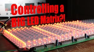
Controlling a BIG LED Matrix?! How Shift Registers work! || EB#39
12:33
야매(??)로 보는 메인보드 리뷰 [보급형인데 보급형같지않은 보급형 네이밍을 달고있는 보급형 보드...(??)]
11:31
Highlight | อัจฉริยะสาวไส้...เบื้องลึกเหตุยิง "สจ.โต้งปราจีนบุรี" | เปิดโต๊ะข่าว | 17 ธ.ค.67
14:51
ไฮไลท์ ฟุตบอล ASEAN MITSUBISHI ELECTRIC CUP 2024 : สิงคโปร์ พบ ไทย
09:54
เนื้อเรื่องที่ท่านจะโมโหจนน้ำตาไหล | Mouthwashing
3:07:15
Julian's Logic: The 74HC595 Shift Register
Julian Ilett
ติดตาม
201K
ดาวน์โหลด
โหลดลิงค์.....
มุมมอง 130 398
0
0
เพิ่มลงใน
เพลย์ลิสต์ของฉัน
ดูภายหลัง
แชร์
แชร์
ฝัง
ขนาดวิดีโอ:
1280 X 720
853 X 480
640 X 360
แสดงแผงควบคุมโปรแกรมเล่น
เล่นอัตโนมัติ
เล่นใหม่
เผยแพร่เมื่อ 13 ม.ค. 2025
ความคิดเห็น • 136
ต่อไป
เล่นอัตโนมัติ
16:50
Как устроены швейные машинки? [Veritasium]
Vert Dider
มุมมอง 1.6M
12:33
Controlling a BIG LED Matrix?! How Shift Registers work! || EB#39
GreatScott!
มุมมอง 557K
11:31
야매(??)로 보는 메인보드 리뷰 [보급형인데 보급형같지않은 보급형 네이밍을 달고있는 보급형 보드...(??)]
정종철
มุมมอง 10K
14:51
Highlight | อัจฉริยะสาวไส้...เบื้องลึกเหตุยิง "สจ.โต้งปราจีนบุรี" | เปิดโต๊ะข่าว | 17 ธ.ค.67
PPTV HD 36
มุมมอง 390K
09:54
ไฮไลท์ ฟุตบอล ASEAN MITSUBISHI ELECTRIC CUP 2024 : สิงคโปร์ พบ ไทย
TrueVisionsOfficial
มุมมอง 1.2M
3:07:15
เนื้อเรื่องที่ท่านจะโมโหจนน้ำตาไหล | Mouthwashing
KarosPPM
มุมมอง 229K
00:56
หลอกเพื่อนจับอึ #funny #แกล้ง #แกล้งเพื่อน #อึ #เพื่อนแกล้ง #ละคร
โฟกัสแอนด์ฟิล์ม แฟมมิลี่แก๊งค์
มุมมอง 367K
19:52
Inside the V3 Nazi Super Gun
Blue Paw Print
มุมมอง 2.2M
13:53
How To Use A Shift Register (74HC595N)
Francis Studios Engineering
มุมมอง 21K
1:07:10
Three-year timelapse of building a secret bunker and renovating an abandoned homestead
Axes: Garage
มุมมอง 2M
19:17
74HC595 Shift Register with 74HC86 XOR Gates
Julian Ilett
มุมมอง 31K
12:38
How to use 74HC595 Shift registers to control mulitple 7 segment displays
Mario's Ideas
มุมมอง 135K
18:26
Unlocking Shift Registers: Arduino Guide to 74HC164 with 74HC595 Comparison!
Mario's Ideas
มุมมอง 12K
13:31
I tried the Cheapest Arduino Alternative (that Nobody heard of)
GreatScott!
มุมมอง 639K
6:04
The Shift Register: Explained [74HC595]
electronica
มุมมอง 117K
25:22
Using an EEPROM to replace combinational logic
Ben Eater
มุมมอง 1.4M
04:03
guncharlie - จากกันโดยสมบูรณ์ | OFFICIAL MV
Kicks Records
มุมมอง 203K
05:43
ส่องฟอร์ม อาหมัด ดิยัลโล่ เล่นโคตรดี | แมนซิตี้ 1-2 แมนยู
สปอร์ตเต็มเหนี่ยว
มุมมอง 96K
1:32:40
ซินเดอเรลล่ากลายเป็นภรรยาของลุงสุดหล่อหลังจากคืนโรแมนติกนั้น ไม่รู้ว่าเธอได้พบกับมหาเศรษฐี
Shop ละคร
มุมมอง 1.4M
00:32
Real Vs Mannequin Challenge😱
Zhong
มุมมอง 17M
1:23:46
【หนังพากย์ไทย】ยอดฝีมือสังหารนักโทษ แต่นักโทษเป็นปรมาจารย์กังฟูที่ซ่อนอยู่ เขาจัดการทั้งหมดในทันที
Fresh Thailand
มุมมอง 468K
01:00
แหกหน้าพ่อค้าจีน 2 #hagatestudio #fun #funny #พากย์นรก
HaGate Studio
มุมมอง 1.1M
01:00
แพนด้าจะไม่ทน #cartoon #cartoonnetwork #short
MuTun Ch
มุมมอง 19K
10:01
Nec Red Rockets Kawasaki vs. LP Bank Ninh Binh - Pool B | Highlights | Club World Champs 2024
Volleyball World
มุมมอง 184K

![Как устроены швейные машинки? [Veritasium]](http://i.ytimg.com/vi/FFW0GcMCgd0/mqdefault.jpg)
![Как устроены швейные машинки? [Veritasium]](/img/tr.png)
![야매(??)로 보는 메인보드 리뷰 [보급형인데 보급형같지않은 보급형 네이밍을 달고있는 보급형 보드...(??)]](http://i.ytimg.com/vi/zMCRuNzHFRU/mqdefault.jpg)


