JK flip-flop

ฝัง
- เผยแพร่เมื่อ 28 ธ.ค. 2016
- Check out my SR latch video first: • SR latch
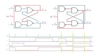
The JK flip-flop builds on the SR flip-flop by adding a "toggle" function when both inputs are 1. The S (set) and R (reset) inputs are now referred to as J (set) and K (reset) to indicate the different operation.
In other words:
J=1, K=0 sets the flip-flop
J=0, K=1 resets the flip-flop
J=1, K=1 toggles the flip-flop
The toggling function is useful for building counter circuits which we'll do in future videos.
Support me on Patreon: / beneater


![ไม่ต้องมีที่ที่ให้ฉันอยู่ แต่ขอแค่มีฉันอยู่ก็พอ (Spaceless) - getsunova [SHORT FILM]](http://i.ytimg.com/vi/MuT0d_cvJkc/mqdefault.jpg)


For anyone wondering about the drawing: The mistake lies in the connections of the Q outputs to the AND gates. Q must connect to the upper AND gate with the J input, while !Q must connect to the lower one with the K input. Now it works as it should: J performs the Reset function, K performs the Set function, and J+K at the same time performs either the Set or the Reset function, depending on which state the Q outputs have been before, a.k.a. it performs the "Toggle" function.
Thanks for sharing
Jesus Christ and I was going crazy to find what I did wrong. Thanks for sharing.
@@tielessin- ditto
This is ridiculous, thank you so much. I was losing my mind trying to figure out how the hell the logic worked with his drawing. Glad to know it's just wrong and he didn't do anything to fix it...
FINALLY!!!! A well spoken English video with a great explanation.
Dont stop
I’m from the future. I’m here to tell you oh boy did he not stop
@Gus Erland If you put your mind, and listen carefully, you'll easily understand the message he's passing across...
@Gus Erland Sure...You are right
Fr tho I'm tired of seeing indians with unintelligible english. No offense.
Not like the other videos weren't speaking english but this guy is different
This guy probably makes some wicked devices in Minecraft with redstone.
:)
Is there transistor in minecraft ?
@@54alexq Kind of? You can make stuff that does all the basic things of a transistor in minecraft but its not in it by itself
@@Mechanist a comparator maybe ? I don't rember exactly, played a long time ago ^^'
@@54alexq yes, just use a piston
The JK flip flop was named after Jack Kilby, the Texas Instruments engineer who invented the integrated circuit in 1958
I was told that it stands for *j*ump and *k*ill
Hes Just Kidding
Both right.
Even my prof in the digital systems lecture (very wise guy) said jump and kill flip flop. But it is named after its inventor.
Thanks for the info.
None of you are right. It's named after how it's described on the patent. The two pins are labelled j and k on the patent.
I love these videos. They take me back to the sixties at the start of my career. As already stated and I agree - The inputs are labeled J and K in honor of the inventor of the device, Jack Kilby
This guy is the only reason I am passing my Digital Logic class
Sir you're the best teacher humanity could ever have, illustrating this subject, on which ever level, be it high school, university or even post grade.
These series of tutorials should be carved into a stone be passed on to learners for millennia
Ben Eater , you are my teacher, and I am a very serious student of yours! I don't have a single competent engineering teacher in my school, even though I go to one of the top highschools in America (I'm not saying which because I don't want this comment on my teachers to be tracked to me personally). I used to take an engineering course, but realized this piece of information for myself and from older students, and dropped the course later. I then discovered you, and now I learn by myself. So that's why I say you are my teacher, because I'm not using you to supplement another teacher or anything; everything I know about circuits is the very basics from Khan academy, and all the very advanced logic and circuits you do. I watched every single video you created and took notes, and create my own circuits, following along to your videos; I'm not joking when I say that I'm a student of yours. I plan to make a big project for school in the school expo making a breadboard computer like yours (with some of my own modification and additions). Without you, I would be nowhere, and know nothing about circuits, and you allowed me to make a big step in my dream of understanding how desktop computers work on a deep level. Your explanations are amazing, and you are a very talented teacher and explainer, very easily sympathizing with the a student's situation of not knowing anything, unlike many others. Your explanations are thorough, and very ordered in the final goal of understanding, taking nothing for granted through your deep understanding, which is probably one of the top things I love about your teaching; you understand and explain things on such a deep level. Not to mention, your a native speaker and aren't annoying or hard to listen to like many other youtubers with Indian accents. I think I speak on behalf of quite a few people in begging you to please continue making videos, and that we appreciate your videos so much, and at least know that you have truly inspired and dramatically changed the understanding of circuits for many people like me, and I'm not trying to be sentimental or anything, I seriously mean it. I really want to be an engineer in this direction. Ben Eater, from the bottom of my heart, thank you for these videos!
Your Latch series is the best explanation I´ve heard so far. Glad to find you out.
Your service is greatly appreciated. A university-level engineering course, tuition free. Thanks for sharing.
good to see you back, man, I love your videos, keep up the good work
+1like
God dammit I was so close to the 69th like
Yayy Ben!! All the nerds of TH-cam smile today with glee! Thanks for the video!! can't say how excited I am to see more of your awesome content!
I greatly appreciate you efforts in term,s of time and resources to create these wonderful videos. I will be taking a Logic class in the fall , and I wanted to experiment with the fundamentals of digital circuit design. I am using CMOS, but I believe I need to get some TTL chips. These tutorials are top notch on several levels.
The “Just Kidding” flip flop
Yay you're back! Thank you for the awesome video :)
Who downvoted this video? Great videos. The joy of building this stuff has added quality and satisfaction to my life. Thank you Ben!
They downvoted the video because the circuit diagram is wrong. Not that the rest of his videos aren't amazing (they are) it's just that this one is a little flawed.
You explain this better than any instructor in my current institution that costs 70k a year. Thank you.
I was fascinated by this circuit back in the day! I thought of this circuit as a means to 'transcend' logic (in logic circuits.) I used it as a random number generator and did many projects needing 'random' logic.
THIS IS EXACTLY WHAT I NEEDED AND WHAT MY LECTURER TODAY WAS UNABLE TO EXPLAIN - Thank god for this little series you have done it has helped me so much
That reminds me of the "Electronic Coin-Toss" we made as our first electronics project in 8th grade.... I think it was just both R and S effectively being high, and a push button for the Enable -- then it'd light up either Heads or Tails as the Q and Q-bar. I don't _actually_ remember the circuit, but it looked very similar.
A famous experiment for JK FF is to set both the J and K high and then connect the CLK to an active high MOM switch, this will toggle the output between HI and LO... The mechanical switch may produce noisy output so the filtering RC circuit is a must.
Wonderful to see you posting again, great video Ben!
I believe this one is faulty.
You have to either switch places on both Q & Q' and J&K for this to work
OR
You have to keep them like that but have the and gates switch their outputs (or gates). And gate on top goes to the or gate on the bottom etc.
So happy to see you back Ben!
Glad you're back! I love these videos! I bought a bunch of discreet electronics parts to build this computer.
Awesome! Thank you Ben! Hope you're having an awesome holiday season!
welcome back :) good to see you again.. can't wait to build the control unit with you!
Hey Ben! The JK in JK Flip-Flop is actually NOT an arbitrary set of letters, it's after the creator Jack Kilby! :) Thanks so much for the vid!
I have discovered that watching to many of these videos in a row makes my head numb and I can no longer figure out what is happening in the circuit. So it, that I have decided that I can only watch onnne ia eeeeeeeeeeeeeeeeeeeeeeeeeeeeeeeeeeeeeeeeeeeeeeeeeeeeeeeeeeeeeeeeeeeeeeeeeeeeeeeeeeeeeeeeeeeeeeeeeeeeeeeeeeeeeeeeeeeeeeeeeeeeeeeeeeeeeeeeeeeeeeeeeeeeeeeeeeeeeeeeeeeeeeeeeeeeeeeeeeeeeeeeeeeeeeeeeeeeeeeeeeeeeeeeeeeeeeeeeeeeeeeeeeeeeeeeeeeeeeeeeeeeeeeeeeeeeeeeeeeeeeeeeeeeeeeeeeeeeeeeeeeeeeeeeeeeeeeeeeeeeeeeeeeeeeeeeeeeeeeeeeeeeeeeeeeeeeeeeeeeeeeeeeeeeeeeeeeeeeeeeeeeeeeeeeeeeeeeeeeeeeeeeeeeeeeeeeeeeeeeeeeeeeeeeeeeeeeeeeeeeeeeeeeeeeeeeeeeeeeeeeeeeeeeeeeeeeeeeeeeeeeeeeeeeeeeeeeeeeeeeeeeeeeeeeeeeeeeeeeeeeeeeeeeeeeeeeeeeeeeeeeeeeeeeeeeeeeeeeeeeeeeeeeeeeeeeeeeeeeeeeeeeeeeeeeeeeeeeeeeeeeeeeeeeeeeeeeeeeeeeeeeeeeeeeeeeeeeeeeeeeeeeeeee ah, this is what happens when you fall asleep for a few seconds while typing. Thanks Fentynal!
You're back! Nice :D. Great stuff as always
seriously, your video saved my whole semester.. thanks a lot
thank you for a new video, i've been waiting for quite some time. Building 8bit computer. Because of your enthusiasm and great teaching.
Thanks for the tutorial, Ben! Helped a lot.
Sweet you are back, make more please.
excellent tutorial!
a great refresher from my college days thanks for sharing!
I don't usually comment on videos, but your videos are awesome.Thanks !!!
Best explanation I have ever watched! Very good work!
Been waiting a long time for this one. :) Good to see you back!
Ben, without having even watched the new video - soo good to have back man!
Ben, after having watched it - thanks for another great explanation. Awesome as always. Hope this is preparatory for the 8-bit computer; I'm guessing for a ring counter?
Just subscribed a few weeks ago. These are so great!!
Thank you very much
I've seen lots and lots of videos explaining this, I guess your diagrams really help
Ben is ALIVE AGAIN!!
I believe there is an error in the layout of this circuit. It seems that when using nor gates you don't want to go from the opposite side nor gate back to the and gates. If you were using nand gates rather than nor gates your diagram would be correct. Since you are in fact using nor gates, you would go back from the same side nor gate to the and gates. Can someone else please confirm this?
I was thinking about it for 30 minutes and searching information and then noticed the error.
Same here man :D
He must have confused it with NAND gate logic for JK flip-flop.
Thanks man! I was wondering for 15 minutes why the state {J = 1, K = 1, CLK = rise} toggle instead of staying in the last state. I knew that it must toggle, but I couldn't understand why. Finally I decided to check in the comments if could be some mistake in the drawing
@@juanma513 check next video, he has corrected the circuit diagram
I learned about logic gates, flip-flops, latches, when I was in 1st-year university, 12 years ago, but the professor did not provide the electronic behind it and how it actually works in the circuit board. I was ultimately confused when I was taught the inner schematic of flip-flop consisting of logic gates and a feedback line. I thought it didn't make any sense at all.
I was studying computer science, by the way. So logic gates, flip-flop, and stuffs were only a part of introductory courses in my major, without actual physical implementation. We only used a computer-based simulator software (Multisim) to create a schematic of a logic circuit. On the other hand, I studied some basic electronics during my high school and was introduced with electronic components including resistor, transistor, capacitor, and so on. But it was really difficult for me to connect between electronics, digital logic circuits, and eventually a computer, and I realized for a very long time that there is a missing link that wasn't really taught by my professor at the university.
But you explained it in a very clear and concise manner, with an actual demonstration, and finally, I understand how the feedback line in a flip-flop works, and its relationship with how a transistor works in an electronic circuit, and even I can finally connect all the dots from the electronic circuit primitives into a real computer.
Thank you very much for all your videos. You said you didn't have a degree but you explained this topic way better than my professor did. You proved that there is something that is really wrong with the education system as you mentioned that your ultimate goal is to improve it. I hope you will achieve your goal, and perhaps you will actually introduce students properly about how basic digital system works. :)
Well I'm taking a class like that right now as a computer scientist, and we still are shown any of it. I guess we are shown diagrams, but not how the signal actually goes through all the parts, most likely since we go through many diagrams in one hour long lecture, so not enough time is given to go more in depth. Crazy how not much changes after a decade and a half in a fast changing field of study though.
Ben please more tutorials on networking security and analysis, im even willing to pay for, you are a genius.
very very thanks sir
you made my sequential circuit easy
thanks for explaining so clearly
Ben, you're amazing
Ben, great video! Eagerly awaiting the continuation of your breadboard computer series.
Also, there's an urban legend floating around that the JK Flipflop was named after Jack Kilby! However, this isn't confirmed. The first time those letters started being used was in one of the early patents for the design, where the patent author chose those letters for some unimportant reason.
I always thought they meant "Just Kidding" :D
love your videos
awesome explanation
Thank you for following up! Some of us were paranoid about the break in vids, given the value of what you do. This stuff is turning me into a programmer. I know a wealth of languages, without knowing what I'm actually doing, which makes me so much worse. "What is a variable really?", "How does a function do?". This is absolutely invaluable. Thank you so much for what you're doing. :)
Thank you for great work, you are a very smart man.
Oh boy... I can't wait for rest of the computer tutorials!
Me too. But I guess he wants to explain the sequencer unit now, so he needs to explain binary counters first, and this in turn requires explaining the T flip-flops first (also known as "frequency dividers" or "count to two"), which are the building blocks of any binary counter. They can be made from the "universal flip-flops", the JK ones. (Well, interestingly, they can be made from D flip-flops as well, but let's allow Mr. BeNeater to explain the JK flip-flop as well, for completeness's sake ;) ).
I, for one, can't wait for the instruction decoder and the control unit, because those are usually the least-explained elements of the CPU in every course I've seen.
Sci Twi Ditto, microinstructions are explained but are never explained how they are implemented...
Xenthera I would also like to see the older way of doing it, with just plain old logic. It can be done easily if the instruction set is specially crafted for that (e.g. some bits in an instruction can select operations in the ALU, other bits can select registers, still other can select the direction of data flow etc.).
I actually built mine with just 2 input nand gates(74HC00) although I have only 4 instructions: LDA, ADD, SUB, HLT.
Thank you very much for the video Ben, it's excellent! Really helped me! The J-K is in honour of Jack Kilby ;)
Perfect ! thank you for teaching this .. it was confusing me
It would be awesome if you made more videos like these where you explain different ICS
sweet, thx for your videos!
A JK flip flop sounds like all the flip flop you'll ever need.
Thanks, i'm going to study these in school soon so i wanted to know them before they teach us them
Thanks for the simple explanation! 😄😄😄
We need to share these videos and really get them out there to motivate Ben. They're fantastically well made and I think we can all agree that they are invaluable rescources for anyone interested in electronics and logic. Keep them coming!
Some say the JK-Flip-Flops where invented by Jack Kilby, but I think it's more like an homage to Jack Kilby that those inputs are called J and K, since Kilby was the inventor of integrated circuits (germanium based, which was invented in his freetime in September 1958) and also the inventor of the electronic calculator. The JK FlipFlop got patented in 1966 (May 18th) by Motorola Inc. (Norman J. Miller) and I think Kilby was only working for Texas Instruments and also as a private inventor/engineer.
Also often used terms are Jump and Kill. Miller did not mention the meaning of J and K, I just looked the patent sheet, he just wrote J and K there.
Since I've started watching your videos I have bought more than 16 breadboards, hundreds of 74LS parts and an oscilloscope...
Thank you for this!
You need to make the SR latch with NAND gates to work as you describe. Great videos explaining while doing the experiment at the same time
It's great to see a new video from you! Isn't there an issue with this flip flop? Surely if J and K are both high then you get the toggle, that's fine. But wouldn't that toggling just keep looping back and forth until your clock 'enable' goes low, eventually settling into some unknown state? Are you just relying on that spike being short enough that you don't get this sort of feedback?
Finally I understand what a flip flop does
Great set of videos (content). Good shooting. Understandable English.
finally! please post more tutorials
Nice info,thanks :)
Ben, I beleive there is an error! When explaining the final schematic, you say that K resets it when it outputs a one, but it seems as if the K output is going into the set input of the S and R latch, you can see that when you go back to the diagram of the S and R latch and see that the bottom input is the Set input. I feel like the K input should go to the top nor gate and that the J should go to the bottom nor gate
Ah i see that you correct it in your next video! Good catch! Thanks again for the videos!
Next video? Where are those? lol
eater.net/bbcpu8-program-counter/
Corey Hulse Yes and a JK Flip Flop is make with Gated SR Nand, not a Nor Latch and the Gated is a "No Gated". So you replace all his JK flip flop's gates by 4 Nand Gate. And you have your JK flip flop.
I was agonizing about this for the last 15minutes, glad to hear it's a mistake from Ben's side =D
good lesson
ure back have happy holidays
two ICs are talking.
-Hi, I'm an opamp. What are you?
-I'm an D flip-flop.
-Wow, seriously?
-Nah, JK.
There is a mistake in the JK schematic diagram - the K works as reset and must be on top and J (set) in bottom. Just compare it with SR flip-flop diagram wich is the same except for the feedback lines from the Q/Q-not outputs.
A guy I worked with used to teach electronics and when he got to the jk flip flop he called it by a very fitting name, the John Kerry flip flop.
man you explained to me something in 10 minutes, and my teacher couldn't do it in an 1hr
Aren't the feedbacks from the output of the J-K Flip-Flop connected the other way around?
Yes I belive they are. And you have to be really careful about your edge detector or the circuit will change state many times and become unpredictable.
A Christmas miracle
I think j stands for "jump" and k for "kill". Nice video though :D
That's what I've been told too
Great video Ben! The fact that the state is unknown when S and R = 1 is very interesting. Maybe it could be used for producing a chance operation. Like a random flip of the coin
sonodrome Unfortunately that wouldn't work. The state the flip flop ends up in depends on the length of the wire and the tolerances of the parts used. So it usually stays the same for every individual flip flop. There is no way you can make a 50/50 chance out of that.
Actually there is, and I once did exactly that. I used a very fast square wave generator (a 555 timer would suffice) to constantly set/reset an RS flip-flop and when the user pressed a button, it latched the flip-flop at the particular state it was currently in, displaying the result. Well, not exactly using the "forbidden" state, but it worked ;)
I think the result would depend on when the user presses the button relative to the current clock state. So it's not truly random, but for all intents and purposes it's unpredictable. You could call it a Pseudo Random State Generator :)
sonodrome With that definition, nothing is truly random. The result of a coin toss depends on the initial conditions (orientation of the coin in the tosser's hand, initial velocity, air flow etc.) and the laws of physics. If you could know all those little parameters and the configurations of all atoms on the coin's way, you could theoretically predict the outcome of a coin toss. But in practice it is impossible, so the result is random enough for all purposes.
"Anyone who considers arithmetical methods of producing random digits is, of course, in a state of sin." [1]
[1] Von Neumann, John (1951). "Various techniques used in connection with random digits”, National Bureau of Standards Applied Mathematics Series. 12: 36-38.
Don't forget to hit the bell icon to get notifications!
Ben's super great, and part of that is not shilling for views, likes, and subs. So let's shill on his behalf!
The inputs are called J-K after Jack Kilby, who invented the integrated circuit in 1958. 😁
best explanation :)
7:00 I think resetting Q when it’s set by giving K =1 and J = 0 is confusing, or wrong.
On clock, K&Q = 1 => lower nor out is 0, I.e., ~Q is 0. Therefore Q is 1. Set Q by making K = 1 not reset Q.
Ah, the Q, ~Q or named wrongly in the picture.
They should be switched. Then the logic will work as you are describing.
Thx for posting a video on jk flip flop which I requested for
I choose to believe it stands for Just Kidding flip-flop
welcome back dude
You have wrong at this time🤭 but you are the guy who responsible i completely understand the deference between SR, D, Flip flop, and JK flip flop. 👍. Well done ♥️
Any idea why this video only uploaded at 480 resolution?
Yeah.. I made a backup for myself of all Ben's videos in 720p, and this one is an odd ball :p Only 360p for me.
I just realized that. Maybe it's because I don't use 4K paper
oh man you need to finish these videos!!! LOL
So... in summary (having been through the set now) SR latch has two inputs, one to turn it on, one to turn it off. A D latch has one input to turn on or off but its state is ignored until the enable is on. A D flip flop is similar but the enable (clock) rising edge is converted to an "enable" pulse to make it only check the input state momentarily. A SR flop flop is similar to a SR latch, but the state of the inputs is ignored unless an "enable" is on (which is actually a pulse created from the rising edge of the clock). A JK flip flop is the same but with some extra connections to ensure the "both inputs on" state doesn't cause unknown behaviour and instead toggles the output in a predictable way. [Note, mainly just wrote this to summarise to myself]
Thanks!
very nice thank you
Lost me on the last bit, glad to see it got fixed.
Ben, any chance you can reupload this one at 1080 60fps like the others?
5:30 if both nor gates are manufactured exactly the same they will start flickering / resonating because both nor gates will turn off eachother so when you conect Power both nor gates will turn on then they will turn off eachother but then they realise that there arent getting any signal in then the cycle reapeats almost in mhz
I need to do this but with 4 push button switches and 2 CD4066 chips. Basically want to switch between 1 or 4 channels on a guitar amp. The circuit in the video would allow for two channels but I dont know how to get the 3rd and 4th ones to work.
JK means Jack Kilby ! Btw really good video !
I have seen the JK stand for Jump and Kill