Amazing Project using an old phone charger !

ฝัง
- เผยแพร่เมื่อ 3 ส.ค. 2024
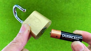
- I modified an old phone charger and made it output 30 volts then, I added a voltmeter screen to use it as a tester for measuring any LED or zener diode less than 30 volts.
- วิทยาศาสตร์และเทคโนโลยี


![[TH] LEV vs TLN | TE vs VIT - VALORANT Champions 2024 DAY 3](http://i.ytimg.com/vi/_AbmrWv2lO0/mqdefault.jpg)


Warning: ⚠ ⚠ ⚠ have fun but always remember to be Safe, anything you try is at your own Risk , thank you
Can you use any phone charger on the table?
@@aivonabeywardana4213 6:44 6:44 Thank you. I have every charger and transformer that ever existed at every voltage. Higher voltage will really help my issues?
@@gaswirt ❤❤❤
Hmm, a neat little circuit, but I worry about folk who don't know what they're doing messing with mains voltages. At the very least, it should be encased in something to prevent straying fingers touching the 'wrong end'.
Thank you for the great solution and footage. Please make another video with the installation of components in which a 110v power supply will be used
It will work in low current range (ae no load), because voltage output element is transformer, that zener only for voltage stabilization via feedback circuit.
Very good information, earlier i show one circuit with multimeter after adding some circuit we able to measure led, zener diode , mcpc ect, and there voltage.
thanks for watching
Thanks to the clear and concise way you explain it makes one want to go do it right now
❤️❤️
if you just turn the pot around, you would get increasing voltage with clockwise rotation....
, 😊😊😊
Why *you{͡ ಠ ̯͡ಠ}* are telling this deep secret ㋛ ! - _? ?_
@@ernstlessau8208he he!!!
careful...folks will be looking for some POT. (Some of that wacky-backie, "smoke it and take a trip and never leave the farm!")
Say Variable Resistor or POTentiometer.
These small switchers are invariably flyback types. Significantly raising the output voltage of the supply MAY result in damage to the switch on the high-voltage side. If you are using an AC line voltage well below the allowed maximum you are probably safe. If your line voltage is already near the maximum allowed, you could destroy the switcher.
The secondary voltage is "reflected" back to the input side and "stacked" on the supply voltage according to the turns ratio of the so-called transformer when the switch turns off and the energy stored in the input winding is being transferred to the output winding. This is the only time that the inductor really acts as a transformer, and it is a design limitation for a flyback converter. Typically the inductor is designed so there is some safety margin between the sum of the peak DC on the input side and the reflected output voltage and the voltage rating of the switch. If you increase the output voltage it may result in exceeding the maximum allowable voltage across the switch which usually causes it to fail short-circuit.
Another potential problem is that many of these switchers use an extra winding on the inductor to power the switcher IC after it initially starts. If the output voltage is set too low the IC may get insufficient voltage to keep it running, resulting in in shutting down, trying to restart, running for a fraction of a second (typically) then shutting down again.
thank you for saving my time!!!!!!!!
Very useful to discover the power of any components.
I have analog version made from little tranformer 30V 150mA with current limiter at few mA so i can check the Zener diodes values up to 30V.....but this is AWESOME idea as well...very compact!!! Will do some of this as well for sure!!!
Your idea is good but this is dodgy as hell somebody will get hurt I think you know this
Thank you for the useful information, you explained it clearly and made it easy to understand! 👌🏻
Verdade
easy to understand......even to lezard-men like you
@@yusufgaridi9523 now you, I don't understand, on account of the fact you make no sense... You're better off blowing things up instead, like national monuments!
Nice!
Looks similar to the TV backlight tester device.
An excellent and necessary device, thank you!!!
Fantástico! Indispensável na bancada de qualquer profissional da área da eletrônica. Parabéns e obrigado por compartilhar. Um respeito abraço do Brasil 🤗 🇧🇷🙏
Obrigado
@@Inventor_AW9l😅
Thanks to you, I can evaluate our old chargers, thank you very much...
Thank you very much for this very useful device. In my opinion because of the voltmeter power supply is maximum 30 Volts, you don't want to excess 29 Volts. If it is possible to increase the output voltage more than 30 Volts, you can add for example 7812 voltage adjusting device and take + 12 Volts for power supply of voltmeter. Thanks again. 👍
I just didn't want to strain the transformer
THAT WAS BEAUTIFUL !
I tried to take an electronics course at a local high school tech night-school, but there weren't but 5 in my class. I was 15 and tge average age was 25 to 40. They cancelled our class & gave us the choice of getting our tuition back or choose another class. I went to MACHINE SHOP.
What you did I followed, but didn't understand the WHY's and Where-fores. I understand, pretty much, what each thing does, kind-of, but not together.
Please do a video on HOW components do the outcome, together. My expertise was rewires and burn-ups on Locomotives. I let somebody else take care of the solid state stuff.
Thanks again fir your content. It was very well done! I'm fixing to SUB.
Excelente video. Sus videos son muy útiles.
Saludos desde Medellin muchas gracias por compartirnos tus grandiosas investigaciones
Bruh, I've got to say this has been one of the best demonstrations on how to desolder components from a PCB. I WILL be referencing this in the future when I move and have time to get into electronics again...
I wish you a good luck
I just did this, was testing a smd LED, touched the uninsulated connections to the power supply inlet with my elbow…. Muscle spasmes and my arm shot out…. Punched the cat….. cat went out the window…. Landed on my old school teachers head….she fell over onto my car and broke my door mirror! Thanks! Now I have no door mirror and a vets bill for a cats PTSD fear of heights and a school teacher that now gives my kids bad reports at school parents evenings! All for saving a couple dollars on a ready made unit!
A wonderful fairy tale .. Thank you for sharing
WOW!!! Thank you so much for sharing your tips and tricks with all of us and I’m very impressed 😊
Well at least it's not as deadly as some - but i'd still look at that transformer closer before using it.
Also most phone chargers will have a '431 reference of their own, so modifications are either easier or harder, depending on the circuit...
Finally, you should never push a transformer winding too far outside it's design voltage, as things get quite inefficient - possibly even dangerous! There is a reason why a relay clicks in the benchtop power supply; it selects three taps on the secondary winding - 0-7V, 7-15V and the final one goes to 30V... Simply looking at transformer action etc. should make it clear as to why it does this (hint: it's to do with 3Amp output current)
Here there is a 10K? resistor, to limit the current - so the power handling is actually not bad...
Muy buen video y excelente explicacion. Muchas Gracias.
Gracias
Grand idea and useful point. I at first thought you were going to just make a adjustable power supply, but what you made was very good a testing device for Zener diode mostly or LED diode power value.
I am still shocked to see the original power adapter have the possibility of 30 volts. I'm assuming that phone charger is a 5-6 volt power adapter, so that Zener diode had a lot of blocking to do.
It is no shock these can still overheat. That voltage drop energy has to go somewhere....
Very interesting noticed
The zener is part of the regulation circuit with the opticoupler, it wasn't directly on the output
@ Ok, I have seen that on a older circuit years ago, the Zener being the last low end regulator after many voltage dropping resistors and capacitors.
I'm guessing that if this is a so called "universal input voltage" model, it won't make 30 VDC in the US. But you are right in that if it was designed like that, there's a lot o wasted energy and heating, built into the design. I guess it's easier and makes manufacturing simple, but it is inefficient.
I'm in the US with the 120v 60Hz standard and I've seen a lot of issues with this universal input designs. Mostly, underperforming issues. I suppose the heat and efficiency issues are more likely in the 240V world.
I hate looking at these kind of videos for a bit and then realizing what they are building was designed for the 240 volt world! I get that there are only about a billion of us using split phase voltage, 60 Hz in the100-125 volt range and that many more people have the 240is volt, 50Hz standard, but realistically, most of those people can't even read!! AW says it doesn't matter, but in many cases it does.
Just my two cents, but electricity as distributed, is not universal. The physics works the same no matter where you live. But when you are modifying consumer goods for alternate purposes, one needs to understand that those items really are universal. Modification you make to devices in one country, very well may not work in another,
@@professorg8383: questo progetto va bene sia per alimentatori per 230 volt sia per 110 volt. La dissipazione è uguale in entrambi i tipi di alimentatore perché il funzionamento è switching.
Muito bom. Assim que eu tiver o voltímetro e o resistor variável, vou tentar fazer, um pois é muito útil. Saudações do Brasil.
Obrigado e desejo-lhe sucesso
I am industrial technician, repairing and installing freeze and cold systems. I´m not into electronics repair, but that looks great tool for you guys. I saw the complete video, very interesting. Thanks for uploading clear and good quality explaining. Best,
Rapaz, muito bom mesmo. Simples mas eficaz. Parabéns pela excelente ideia. DEUS continue te abençoando.
Obrigado
Adoro eletrônica parabenizo vc por compartilhar seus conhecimentos 👍
Why waste our time. Tell us at the start what this is supposed to do.
Exactly.
It's supposed to test the rated forward voltage of diodes by dropping down to their voltage when connected. One slip & you electrocute yourself it's stupid
are you a puny and arrogant muslim?
@@neiliewheeliebinmost of these electronic channels are
Diode tester. It works to seek the voltage of LEDs and Zenners. And it drives LED series.
Good job, Thanks a lot.
Neat little project. :) The video is easy to watch and listen to. It was good to clearly see how to desolder; I haven't had enough practice at that.
❤️❤️
So nice to see a fellow who actually knows how to solder!
thank you bro
*Не стоит забывать о том , что не смотря на изменение выходного U , выходная P (мощность) = остаётся прежней* ☝
Nice trick, don’t forget to change the output capacitor to one with 30v or over
I replace it to 50V cap
Que bueno !!! Te felicito un buen probador de diodos comunes , zener y led, lo voy hacer , gracias amigo . y Viva la libertad, carajo !!!
VLLC!!!
Gracias y buena suerte
Interesting, but I would have picked a better charger to modify. That's one of those dangerous Chinese suicide chargers that doesn't even have a fuse or interference filter, and if CY1 is really a Y-rated capacitor and not just a 1KV cap I'd be surprised. I don't even like having those things around.
Acho sensacional esse tipo de recurso eletrônico para recuperar aquilo que está danificado e até melhorar o seu funcionamento. A eletrônica sempre me fascinou desde de criança. Meu pai estudava eletrônica via correios e chegou a montar um rádio. Enfim, o video foi muito interessante.
Obrigado ❤❤
Meu falecido pai aprendeu pelo instituto Universal Brasileiro, todo mês saia um livro diferente, chegavam partes do circuito todo mês pra montar.
ну радио это круто, но мой дядя собрал компьютер в 88 году, и это делали очень многие советские студенты) называется zx spectrum.l
Very wonderful idea
Depending on voltage drop in wattage is how much heat your have to absorb
Don't mess around with high voltage ⚡
Maybe he's just giving advice
Sir please make a video about auto on off timer circuit for any project.
I will
great idea, but LEDs are current sensitive it means that if more current is passed than what a led is designed for , it may cause burning. most of 5mm LEDs requires about 20mA to work properly. so how output current is controlled!!
There is no worry about current because there is a 10k resistor connected in series with the voltage source. On the other hand, the voltage rises at the expense of the current decrease
it is quite dangerous to OVERCLOCK the fly power supply at 6 V to 30 V with such a power, the reverse voltage on the output diode will grow (up to 250-300v) and it needs to be changed!
but what is much more dangerous is the gratifying voltage on the 1 winding and the corresponding impuls on the MOSFET DRAIN inside the PWM CHIP! if it exceeds the limit for them (and this is very likely), then there will be a big EXPLOSION and possibly a fire!
but the idea itself is of course interesting, just for the correct and safe release of it, you need to recalculate and rewind the transformer for your new voltage and replace the diode with a corresponding voltage 400-800v ulta fast diode!!!
... and his mounted Resistor is instead of 10 KΩ = 1 KΩ :
brown-black-black x brown ➜ 1-0-0 x 10¹ ≙ 1000 Ω !
And why no one did realize that ! - ? ? { ͡ ๏ ̯͡๏ ?
Yes, it can destroy the mosfet, but the reverse voltage on the output diode will be about 60 v, not 250-300v.
@@mikemir6738why?TheMaxVoltageIs EfectiveVoltage times 1.41 🤔?
@@ovidius2000 On output side U max = 30 V. M1U schematics (wih middle point) : reverse voltage on diode = 2*Umax out. If you have fullbridge rectifier : Urrs = U max out.
Wow it's so awesome. Really I fulfill my all requirement from this project. Thanks to share this knowledgeable video for us.
"The Technical Learner"
( Mr.Chandrakant.S, From India.)
Ferramenta excelente!
crt tv fly back nosel which is having high heat resistance, cut the half inch straight part and push on soldering sucker that work well and this way sucker white plastic tip will not damage the pcb.
Please make a short vlog on this.
I will
i advice you to use a piece of silicon cable isolator for your soldering pump's end pipe.
it's original part is normally too rigid plastic and you can buy a lastic cover but they are expensive, whereas 2-3 cm silicon cable cover is almost free and more useful than original one.
Thanks for the advice.. Yes I know it and you can find it on an old CRT TV high voltage transformer cable
@@Inventor_AW
i don't know your country's trade conditions but we can find the silicon cables at any electrician shop. for this application (to cover soldering pump edge or mouth) it's ideal just 6 mm outer diameter of cable isolator.
I like how you explain what the name and number of the part your using
thanks for watching
I own an UT33C since 2016.
Hi, I never through old electronic stuff and it very often find its use, even just for study of their design and not only electric parts ...
Regards
Jean-François
That 470 uF 16v cap dies anyway on these units anyway. Even without the mod it’s a good idea to replace it.
I'm assuming he replaced the cap with a higher voltage rated one. Otherwise the original cap would have popped like a party favor when the output was cranked up to max.😳 you could use an LM317 too.
this is zener diode checker and tester.. briliant...
Muito útil o equipamento que construiu!
Desejo-lhe sucesso na vida e sucesso profissional.
Obrigado
Gostei muito do projeto, só tenho uma, a fonte utilizada foi de 6v 1A,mas esse projeto eu posso utilizar em outras fontes como de 5v, por que é a fonte mais utilizada nos dias de hoje, ou eu tenho que utilizar o mais próximo do seu projeto, porque eu gostei muito e doido para fazer.
Obrigado por divulgar o seu ótimo trabalho.
Eu te desejo sucesso
Thanks for tutorial yhanks for sharing.. 👍
Excellent work. Great explanation.
thanks
Great video waiting for more
thanks
Ferramenta incrível. Vou fazer uma tbm. Obrigado
Boa sorte
Exposed wires carrying mains voltage is very unsafe. To everybody who are reading this comment, please be careful of the high voltage and insulate it to reduce chances of getting electrocuted. Everything you do with electricity is at your own risk. Thank you 🙏
It's amazing! Thanks a lot!
I wonder how many times you got shocked by the mains during making this.
0
Grazie! Molto utile per scoprire la tensione di qualsiasi LED.
Solche Netzteile können Tödlich werden,wenn es einen Durchschlag der Netzspannung zur Niedervoltseite gibt.Ein Trafo ist 1000 Mal besser.
Es enthält einen bereits isolierten Transformator
Earned a sub. Great content!
thank u
Great except phone chargers aren't analogue devices any more, they all have logic in them that negotiates current and voltage with the device you connect them to.
Instructions unclear, my phone melted and will not charge.
I built one, it works well, thank you.
good
Well done!
how to blow up on board capacitor 101. MAKE SURE YOU REPLACE THE CAPACITOR TO THE HIGHEST RATING ON OUTPUT!
I replaced the 470p-10v output capacitor with 470u-50V
Thank you sir! very amazing! But what happened to LED?
which LED?
ahirnya ketemu juga tutorial yg saya cari cari terima kasih boss 👍 sukses buat anda 🙏
Please make a video with the installation of components in which a 110v power supply will be used
the same coponents
@@Inventor_AW thanks for the solution
This is a super cool device that I would have had use for recently! Instead, I took LEDs of differing voltage ratings and a whole bunch of resistors to make them equal brightness.
Question: how can this circuit measure the "voltage" of an LED, which obviously can be safely run at different voltages? How does it find the nominal or ideal voltage?
A semiconductor PN junction has a certain forward voltage, depending on physics and chemistry. If you apply a rising voltage to it in the correct direction, nothing happens until that threshold voltage is reached and then current starts to flow. Raising the voltage will dramatically increase the *current* flowing through the junction, while the voltage across remains fairly constant, until it overheats and dies. Here a 10k resistor is put in series to limit the maximum current. The 30V is high enough to turn the PN junction on, which then remains at its forward voltage, with the remainder dissipated across the resistor. The voltmeter simply measures across the PN junction, showing the forward voltage, which is relatively independent of the current.
Well explained
This is an incredible explanation, thank you so much!
Thank you for sharing this video. 👍 👍 👍
❤️❤️
Спасибо за Ваши видео !👍
Спасибо
And the fact that the PWM controller will be powered by more than 6 times the increased voltage does not matter?
Sir, the voltage has gone up and the ampere has gone down. As you can see, it is only used for testing and has not been overloaded
Let me just remind you, that about a billion people do not use 240 volts.
it doesn't matter
@@Inventor_AW Depends on how the charger is made. If it is a "universal input" type, it might, but the DC voltage out if the rectifier is going to be lower to start with. That's because the AC output of the transformer is lower. The DC is still enough so the charger still works but the max DC will be lower.
You don't give a full schematic so I can only make some assumptions, But I would be surprised if you could get 30VDC output with a with a 120v input.
You have some interesting ideas but they may well not work everywhere and might even prove to be hazardous. You could use to improve your disclaimers and also note in your page description, that you use the 240v 50Hz standard.
That is nice soldering !
thanks
@@Inventor_AW I have soldered for well over 30 years, no expert, but well trained !
@@andygibson8143 All respect to you sir
Simplesmente incrível. Muito bom ! Parabéns !
Obrigado
Не плохо вы очень просто придумали, как проверять светодиоды сколь они употребляют напряжения, с уважением Евгений. 💯👍
Ah, recreating the buck step down/step up converter. except with those you can independently adjust current and voltage.
Awesome! Thanks!
Very informative and creative
thanks
Всё! У забытых зарядок начнётся новая жизнь :)
Super job
thanks
Супер ))) Отличная приспособа получилась !!!
Simplesmente brilhante a idéia! Só queria saber se podemos fazer com fonte de 5v? Saldaçoēs do Brasil🖒
O importante é que ele contenha um circuito de realimentação semelhante ao que usei no vídeo
here multimeters are cheap at harbor freight, etc. Does this do something a regular multimeter can not? It might be more useful to use a case mountable potentiometer that can be easily adjusted and make this into a variable power supply. you could use this voltage display or use a voltmeter ammeter display.
muito bom maravilha de ferramenta amei
Thanks ... I'm going to try that..
good luck
I like the GND and the kiloohm.
because I use text-to-speech software
Facinating....had no idea what I just watched though.
i converted an old phone charger to LEDs & zinner diode tester
would this work with a 2 wire (red/black) voltmeter? and how would you alter the circuit in that case?
2 wire voltmeter won't measure less than 3V
I AGREE,I HAVE WORLD CLASS COLLECTION. SO MANy INTERESTING USES!
Excelente tu proyecto y muy practico.
gracias
Que Coisa Realmente fantástica , parabéns ótimo conteúdo, ganhou um inscrito , gosto muito de eletrônica.
❤❤
essa pecinha azul serve para aumentar e diminuir a voltagem? por que tem um no AVR do meu gerador e eu aumentei e vi que mesmo ele em marcha lenta a energia ficou mais forte, só que não sei se isso pode estragar ele.
Excelente ideia. Vou fazer para mim tambem.
good luck
you are a genius
thank you
"Watch to the end".
Okay then.
Start watching at 5:10.
There a idea of construction:
Zener diode tester, with 10k series rezistor to DC 30V modified adapter output.
Scheme of TL431 mod: 1:20
Hi What are the specs of the phone charger you used to build this?
Chinese charger 2 amp