Thank you for the expalnation ! This video helped me understand this 555 timer very well and helped me secure my degree apprentiship.Thank you legend 💪🏿
Wonderful job on the whole series of the 555. Honestly, I feel confident of finally having a somewhat firm grasp of the infernal working of this chip after your explanation. Oh, and I do mean infernal, not internal.
You can also control the charging and discharging of the 555 astable multivibrator with its output pin. In this case you just need 1 capacitor and 1 resistor. If you use the symmetric CMOS versions of the 555 timer you can achieve exactly 50% duty cycle in this way. You can also use a bidirectional current source instead of the resistor. In this way you get linear charging and discharging behavior, leading to a triangle wave at pin 2 and pin 6. If you use a full wave diode rectifier as current swith and a current source from Vcc and a current sink to ground you can control the pin 2 and pin 6 from the output pin with 2 different currents for charging and discharging of the capacitor for asymmetric duty cycles. This circuit is easier to make than an asymmetric bidirectional current source, except you simply use 2 different constant current diodes in antiserial configuration (a constant current diode is in fact an NJFET which behaves in its opposite current direction like a diode in forward direction).
You have used the word "and" 8 times 🅐🅝🅓 that was excessive! To quote: "You can also control the charging 🄰🄽🄳 discharging of the 555 astable multivibrator with its output pin. In this case you just need 1 capacitor 🄰🄽🄳 1 resistor. If you use the symmetric CMOS versions of the 555 timer you can achieve exactly 50% duty cycle in this way. You can also use a bidirectional current source instead of the resistor. In this way you get linear charging 🄰🄽🄳 discharging behavior, leading to a triangle wave at pin 2 🄰🄽🄳 pin 6. If you use a full wave diode rectifier as current swith 🄰🄽🄳 a current source from Vcc 🄰🄽🄳 a current sink to ground you can control the pin 2 🄰🄽🄳 pin 6 from the output pin with 2 different currents for charging 🄰🄽🄳 discharging of the capacitor for asymmetric duty cycles. This circuit is easier to make than an asymmetric bidirectional current source, except you simply use 2 different constant current diodes in antiserial configuration (a constant current diode is in fact an NJFET which behaves in its opposite current direction like a diode in forward direction)."
Hi Netanel! .693 is just a constant used in this case, there's some debate about where it came from or how it was precisely calculated and, frankly, I don't know what is the truth of its origins. However, it has been confirmed empirically as the factor needed to make the math line up with reality and, showing the engineering (versus scientific) side of me, I haven't worried about it too much.
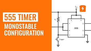
Hi, I read the comment by @gkdresden and have a question. For context I have set myself a goal of building a modular synthesizer. I'm in the process of designing the VCO module and I will be using the 555 timer IC as a core for the oscillator. The question I have is: Can you get rid off R1 that is show in the schematic or do you "blow up" the 555? Thanks for the very helpful videos!
Hmmm... that's an interesting question! It does seem like, by getting rid of R1, you will be connecting VCC directly to GND through the internal BJT of the 555 timer. So, yeah, essentially blowing it up. However, there's nothing like firsthand experience! If you have some extra 555s on hand, try it out and let me know what happens! Just use safety goggles, don't hurt yourself, don't sue me if you do get hurt, etc. 😀
Yep, it will never be exactly 50% duty cycle but, depending on your application, should be close enough for most cases. Though not being able to do less than 50% is pretty limiting. There are additional things you can do to achieve less than 50% but it requires additional components.
Depends on what the situation is. Of course, this can take up to 18V and if you just want to raise the voltage of the whole system, then that's pretty easy and shouldn't affect the timing. You could even do a quick op-amp amplifier circuit on the output. I'm not sure how you would get a resistor connected to the base of the internal BJT... or do you mean an external BJT? Yeah, a BJT or even a FET amplifier circuit seems like it would work well.
@@CircuitBread yeah an external BJT. i was thinking the output voltage being connected to a resistor to get some output current, which goes into the base of an external BJT and the amplification goes from there. completely forget that directly connecting to an opamp in the output is possible haha
Depends on the duty cycle and frequency you're looking for! The written tutorial goes more into depth on the calculations and also doesn't move around so you can copy them down easier: www.circuitbread.com/tutorials/555-timer-4-astable-multivibrator-configuration


A series of Sergey projects doing cool stuff with the 555 would be gold
Oh, I like that idea! He is crazy busy at the moment but I think he'd really enjoy working this.
I feel pretty confident in understanding the internal components and processes of the 555 after watching this video, thank you :)
Good explanation. The capacitor discharging through the Q output transistor is missing in many videos that I've seen.
Thank you for the expalnation ! This video helped me understand this 555 timer very well and helped me secure my degree apprentiship.Thank you legend 💪🏿
Glad it helped!
Thank you so much for your explanation! This is the best explanation video on 555 timer that I have watched on youtube.
Glad it was helpful!
Wonderful job on the whole series of the 555. Honestly, I feel confident of finally having a somewhat firm grasp of the infernal working of this chip after your explanation.
Oh, and I do mean infernal, not internal.
Haha! Trying to keep everything straight internally made me sometimes think of it as an infernal IC...
You can also control the charging and discharging of the 555 astable multivibrator with its output pin. In this case you just need 1 capacitor and 1 resistor. If you use the symmetric CMOS versions of the 555 timer you can achieve exactly 50% duty cycle in this way. You can also use a bidirectional current source instead of the resistor. In this way you get linear charging and discharging behavior, leading to a triangle wave at pin 2 and pin 6.
If you use a full wave diode rectifier as current swith and a current source from Vcc and a current sink to ground you can control the pin 2 and pin 6 from the output pin with 2 different currents for charging and discharging of the capacitor for asymmetric duty cycles. This circuit is easier to make than an asymmetric bidirectional current source, except you simply use 2 different constant current diodes in antiserial configuration (a constant current diode is in fact an NJFET which behaves in its opposite current direction like a diode in forward direction).
You have used the word "and" 8 times 🅐🅝🅓 that was excessive!
To quote:
"You can also control the charging 🄰🄽🄳 discharging of the 555 astable multivibrator with its output pin. In this case you just need 1 capacitor 🄰🄽🄳 1 resistor. If you use the symmetric CMOS versions of the 555 timer you can achieve exactly 50% duty cycle in this way. You can also use a bidirectional current source instead of the resistor. In this way you get linear charging 🄰🄽🄳 discharging behavior, leading to a triangle wave at pin 2 🄰🄽🄳 pin 6.
If you use a full wave diode rectifier as current swith 🄰🄽🄳 a current source from Vcc 🄰🄽🄳 a current sink to ground you can control the pin 2 🄰🄽🄳 pin 6 from the output pin with 2 different currents for charging 🄰🄽🄳 discharging of the capacitor for asymmetric duty cycles. This circuit is easier to make than an asymmetric bidirectional current source, except you simply use 2 different constant current diodes in antiserial configuration (a constant current diode is in fact an NJFET which behaves in its opposite current direction like a diode in forward direction)."
Of you increase the voltage at the base of transistor, it goes into saturation mode. Basically a wire from collector to emitter.
Nice job explaining this. Very clear explanation!
You can use the astable multivibrator also to generate sawtooth functions.
Useful suite of 4 videos, Thanks .
Dang, amazing job and explanation. Only 218 likes, what a shame.
Subscribed!
Awesome! Thanks and welcome!
Well explained...
Thanks for this video,
wondering about the 0.693 portion in the mentioned time equation,
Hi Netanel! .693 is just a constant used in this case, there's some debate about where it came from or how it was precisely calculated and, frankly, I don't know what is the truth of its origins. However, it has been confirmed empirically as the factor needed to make the math line up with reality and, showing the engineering (versus scientific) side of me, I haven't worried about it too much.
@@CircuitBread thanks for the quick reply!
Hi, I read the comment by @gkdresden and have a question. For context I have set myself a goal of building a modular synthesizer. I'm in the process of designing the VCO module and I will be using the 555 timer IC as a core for the oscillator. The question I have is: Can you get rid off R1 that is show in the schematic or do you "blow up" the 555?
Thanks for the very helpful videos!
Hmmm... that's an interesting question! It does seem like, by getting rid of R1, you will be connecting VCC directly to GND through the internal BJT of the 555 timer. So, yeah, essentially blowing it up. However, there's nothing like firsthand experience! If you have some extra 555s on hand, try it out and let me know what happens! Just use safety goggles, don't hurt yourself, don't sue me if you do get hurt, etc. 😀
Thanks
does the BJT voltage mean we won't ever get exactly equal high and low intervals?
Yep, it will never be exactly 50% duty cycle but, depending on your application, should be close enough for most cases. Though not being able to do less than 50% is pretty limiting. There are additional things you can do to achieve less than 50% but it requires additional components.
if i wanted to raise the output voltage of the whole thing, what kind of amplifier should i use? does a resistor slapped to the base of a BJT enough?
Depends on what the situation is. Of course, this can take up to 18V and if you just want to raise the voltage of the whole system, then that's pretty easy and shouldn't affect the timing. You could even do a quick op-amp amplifier circuit on the output. I'm not sure how you would get a resistor connected to the base of the internal BJT... or do you mean an external BJT? Yeah, a BJT or even a FET amplifier circuit seems like it would work well.
@@CircuitBread yeah an external BJT. i was thinking the output voltage being connected to a resistor to get some output current, which goes into the base of an external BJT and the amplification goes from there. completely forget that directly connecting to an opamp in the output is possible haha
Nice ❤
does the capacitor start discharging at exactly 2/3 Vcc?
so when the circuit runs, capacitor voltage ventually goes up and down between 2/3 Vcc and 1/3 Vcc?
Yep, exactly!
What will be the values of R1 R2 and capacitor?
Depends on the duty cycle and frequency you're looking for! The written tutorial goes more into depth on the calculations and also doesn't move around so you can copy them down easier: www.circuitbread.com/tutorials/555-timer-4-astable-multivibrator-configuration
huh interesting... the high voltage seems slightly linearly descending down ... not exactly a square wave
Yes, it does droop a bit over time, which would be a problem in analog circuits but are probably fine with anything digital.
First?
Ha! I didn't know this was still a thing. Congratulations on being first! 🎉