@squirrelposse Yes, thanks for clarifying this. The PLC controls the motor starter which is designated 'M' and the motor starter actually handles the making and breaking of the power to the actual motor. And yes hurlexkid, a motor starter is basically a big relay.
@Thrashaero Yes, the symbols you mention are electronics symbols. There is a whole different accepted symbol library for electrical drawings and another set for instrumentation.
@hurlexkid Not really. On the program you see it says M1 in the green square. But if you look below it says Q-2 which means its a contactor. You can also see it's a contactor by seing where it is used.
@Foaman - I agree and may have a chance to do that on our website soon. I had envisioned creating some videos I called 'ride alongs' where I could create a combination of video of the equipment and screen captures. Unfortunately most of my clients will not allow this do to the proprietary nature of their businesses. I have a client that is out of business that I am working on putting together some vids I captured and could not product. just have to find the time...
@nobodysfool454 The video has been on here four years. I think any problem you found with the video has been discussed and discussed some more. There's only one that I can remember; however, the point I was trying to make was made. Chances are if you can find a problem then you dont need an introductory to PLC's. If you need one then all the points I make are valid. I have found my Electrical Engineering degree to be very useful. Got me my first job and a foundation to build on.
@zaganfallenengel - I would take it a step further. I think this is a better medium for controls training than the traditional methods. This allows the advantages of a course being taught over time (similar to college but with an instructor that has seen a plc). Most industrial training seems to be cram course style. That means the student forgets most of what was learned the week after the course. This method also allows us to make the student struggle to complete programs.
Our rule of thumb is to never use latches unless you specifically have to. Use seal in circuits for those purposes. There are times when latches are the only way, but they usually are difficult to troubleshoot and understand in a larger program. It is useful sometimes to complete a program in "small bites." Program a little functionality - get it to work. Then program the next bit of functionality. Try getting the up and down seal in circuits first-then modify for the rest of the functions.
I spent many years working in maintenance industry and retired as a maint engineer and spent time training those starting out. After retirement I always wanted to continue my training but never have still have the ability.
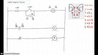
Well the explanation is correct, but there are some issues with the diagrams. The overall points I make are correct. Jump is making the point that around 3:30 in the time line the normally closed stop contact in the ladder logic should be a normally open contact. This is true if you were to take those pushbuttons in the hardwired diagram and take them directly to the PLC as inputs. The diagrams are representations of hardwire vs. ladder for discussion. They work for that.
@MYTOWER Overloads should be hardwired into the motor start circuit. On a rare occasion (maybe once or twice in the last 25 years) I have had a client that is willing to pay to have a separate contact brought into the PLC. Since the costs on all systems are limited, there is usually more important information that people are interested in seeing. I dont think I included it in my motor circuit example, but I didnt want to confuse someone that is just figuring out what a seal in is.
It depends in the actual hardware you are using if the stop button is a normaly open pushbutton then XIO instruction its ok, but if the stop poshbuttton its normally closed (like an mushrom e-stop) then XIC its ok. Good Video thanks automationnc
@WILLIAMDETHUONG "M" is the designation for the motor stater "M" not for motor, the starter only makes or breaks the connections that lead to the actual motor or load.
To program PLC's it is good to have a general programming knowledge, but also it is good to have a good feel for electrical circuits since that is what the ladder logic language is based.
Ok, beer is always welcome... Especially considering you are from the UK. We are working on putting together a larger offering on our site, but we are not there yet.
That really depends on what type of hardware is being used by the user. The simulators/emulators are specific to the particular hardware. In the US Allen Bradley has an advantage in market share so I would venture to say that their emulators are more widely used. In the rest of the world Siemens tends to hold hardware market share thus I would expect their emulators to hold sway.
@nobodysfool454 wow thanks for such an eloquent response. Actually the name of our site and its learning philosophy came from the fact that my training has pretty much been learned from mentors throughout my career. The only training I have had has been required by projects or manufacturers. That is where I learned that the cram course stuff doesnt work. I did teach some at a local college that had a good lab and that worked well. Unfortunately, few profs have actually installed a system.
If I understand correctly, between the physical switches and the make and brake symbols of a plc, the bits mediate. The bits have an initial value of '0', so it coincides with the normally open state of a contact, while the same is not true of the initial closed state of a contact in the ladder diagram, which for any contact to open, the input bit must change from 0 to 1
Take us to the field, my friend. Your coloring is very neat and pretty, but I wish we could take a field trip. I've never busted one of these machines open. ^^
@plchacker As you say it has been addressed many times, I wont bother replying again on that subject. It serves its purpose. As for calling the instructions contacts and coils, once again serves its purpose. I dont think anyone watching these videos has mistaken what I am saying. Over the years I have found that thinking of them as contacts and coils helps most to understand what is going on with the logic especially since most people maintaining the PLC's have electrical backgrounds.
No, it only causes confusion between software INSTRUCTIONS and hardware CONTACTS AND COILS. This is a lazy way of teaching this and will not help your students.
Ok I think you both misunderstood my second comment which was referring to what I said in the first comment... I was referring to using a normally open CONTACT in the program which would have to be tied to a normally closed pushbutton to work properly.
@automationnc i think it will still function if they really used NC contact stop switch as an input.. i am not sure now.. but i know this very well 2 years ago..i have bad memory damn
@stalinwasright The best way to get involved with PLC's is working with the real thing. Rockwell also has a freebie programming package and emulator that work well. We have links and details on our PLCMentor site. The best way to learn programming is by programming PLC's or otherwise; however there are many wrong paths that can be taken so I suggest finding a knowledgeable mentor at work or we have designed our site to help fill that role.
For this example and with no input conditioning prior to block execution you would be 100% correct. As the annotation in the movie also indicates. (I cannot tell if it was there 4 months ago :S)
It depends on what you use as a pushbutton sir. As you know the N/C pb would be used, you touch the N/C pb and it would be a stop button. I'm not saying you're wrong, this is justa different way of doing it.
Sorry I just noticed that my reply to you did not go through... In a PLC the CPU runs the program repetetively. Each run is called a scan. With most PLC's the inputs are read before each scan, the program is scanned and outputs are set after according to the program results. I will need you to reword your relay question as I do not understand. And yes... this could be more informative. Always. We have more vids with more detail at our PLCMentor site.
Hi Automaticmc. I watched your part 1 introduction to ladder logic. I would like to watch the continuation of that video I'm assuming would be part 2 but I do not see it anywhere on utube list or your directory. Does it exist? just curious. thanks, Jimmy
ok, I'm used to M1 with the circle symbol meaning a meter, and M1 with the parallel lines on the conductor meaning a capacitor......what is this separate school of symbols?
I would say CoDeSys from 3s, it supports all IEC 61131-3 standard programming languages including ladder with simulation via a virtual Hmi or machine. However I would not dare to suggest it is the "industry" standard, infact in my limited experiance as automation programmer every single company and machine builder uses their own prefered standard. Often dictated by "what is on the shelf" as spare parts.
well now theres some questions after hearing this introduction . what when why & how ? what processor scan is polling for data updating what data table? Why is the data being frequently being re-scanned? How does the live feedback from the relay being status checked differ from a direct connection into the ladder loop? can this be any more informative ?
@45johnmilne i think it will still function if they really used NC contact stop switch as an input.. i am not sure now.. but i know this very well 2 years ago..i have bad memory damn
I hate it I've been struggling with the door simulator trying to use two sets of latch and unlatch and also OSR's. What Im trying to do is to have the door stop everytime I push the close button while the door is moving up and a second time to actually close the door back down or viceversa. HELP!!!
Good video but pity that the ladder logic diagram is wrong. The configuration shows a normally closed stop switch which is usual in practice and this should be shown exactly the same as the normally open start switch on the ladder diagram. This is a common mistake in a lot of educational textbooks on the subject. See Fraser & Milne "Electro-mechanical Engineering - An integrated Approach pub by IEEE press 1994 for a correct description.
Hey man, sorry for the bad news... but at 4:00 or so, your logic is wrong. According to your logic expression, the stop button is an XIO (examine if open), but the drawing clearly shows the pushbutton is normally closed. Your circuit will not work. You need to change the XIO of the stop button to an XIC (examine if closed) for this to work.
@nobodysfool454 wow a little hostle - you must be a joy to work with. Wasnt me that did your cornflakes so take it out on someone else. College was a ways back for me - I was just pointing out that there can be benefits. Yes many make it in to engineering programs but not many complete it do they? Yes my resume also probably would look good. Who hires by resume though? As for the content, I dont need to research it, I do it every day. I like to share what I know - you dont have to watch.
No problem. You can go to our site contact page. I am not an S7 guy, and all our Seimens proficient people are on startups. You can send me a question via the contact page and I can forward it to one of them. rw
all you need to know is Ladder Logic, its made for electricians more then it is for programmers. If you know electricians you don't even need to know the basics like HTML
Nice explanation, too bad it's wrong. You've programmed the stop button as an XIO (examine if open) contact; the actual stop P.B. contact is sitting closed, therefore the PLC ladder rung would always be false, the motor would never start. You'd have to hold the stop button open and press the start button to start the motor. Quick fix: change the stop button instruction to a XIC (like the start button instruction) and it'll work.
I like this video, I want to learn this programming for ( PLC ) about the hardware schematic and ladder diagram no problem I know it already. start/stop Y-Delta and reverse forward. now present working as technical specialist of Siemens Saudi Arabia LTD. by testing and commissioning of BMS system using X-work plus programing and Desigo insight Simatic.
can anyone help me with a plc problem im stuck with if somone could reply with a solution that would be much appreciated: problem: The process cycle is started by pressing the start switch the start switch, which puts on a system running indicator light and the conveyor belt motor. Boxes pass along conveyor belt and will be measures by sensors 1 and 2. When a box is detected at the sort solenoid the belt will be stopped. If it is a short box it will be pushed off the side of the belt. If it is a long box the auxiliary motor Am1 (simulated by a light) is activated for 3 seconds. The belt will be restarted and a long box will be allowed to pass off the belt. The system should put the belt main light off when the third long box has passed off the belt. If the stop button is pressed, everything should stop and the system reset.
+lewis stevenson Seems more like you are looking for someone to do your program for you. If you have a question about what instruction to use for a certain task or why something isnt working, then post it to our forum on PLCMentor.com and someone will help. Its not likely you will find someone to reply back with a full program as a response.
+lewis stevenson It is not about the teacher, it is about you. There are good teachers and there are bad ones. I am getting interested in PLC and for last weeks I've been searching/watching/reading and working on some basic tutorials and I still didn't find one it would be perfect :) So I am all over the place and learning as the project (I am working on) demands it. So, find a good book (In Us there are great books about PLC for ex. A Guide To Understanding PLCs by Phil Melore (The PLC Tutor) Programmable Logic Controllers Hardware and Programming by Max Rabiee (Goodheart-Wilcox) Programmable Logic Controllers by Frank D. Petruzella (McGraw-Hill) Fundamentals of Programmable Logic Controllers, Sensors, and Communications by Jon Stenerson (Prentice-Hall)) And put some extra hours in it.
no this teacher is terrible its like he doesn't want us to pass and i get frustrated on pressure like that.especially went i cant research my problem because noone has the specific setup we use
use my poor english to answer some questions button & relay have NO & NC PLC also has NO =|| NC=|/| button & relay have same lable but different address zone.
Good effort but has been mentioned many times your logic is wrong. If you choose to continue down this path you will sooner or later cause problems for unsuspecting people who believe you. Further, you also make the mistake of calling PLC instructions "Contacts" and "Coils." That is wrong. They are not hardware devices, they are software instructions. They refer to the I/O and other data tables. I have been programming PLC's for over twenty years.
@nobodysfool454 Oh and something I guess we can agree on. I would never hire some "bonehead" because he has a degree either. I wouldn't hold it against him either.
well first of all thx for the reply please don't u have an e-mail adress i'm workin on a project and i need some assistance i know it's too much to ask but here i am there is no harm in tryin
In 10 years 1M people have watch this video on which you refer to instructions as contacts and have a stop PB wired NC (which is basically law) and have it assigned to a XIO INSTRUCTION... To never correct that is some kind of lazy..
Referring to instructions as contacts is something I still do to this day as do many in this business. Actually a stop button wired to the PLC does not work in the same manner as a hardwired button so there is no "law." It's not lazy, but it is the fact that this was the first video ever on PLC training on youtube. To me it has some significance because of that. But please - post videos of your own and I will be happy to come and critique! ;)
Shit. I'm so very jealous of my brother's best friend at the moment. He's actually been single for life. Yet somehow he's got a swimwear model to state to him she loves him in under a thirty day period. Just how can that be achievable? He smiled and told me he tried the Cupid Love System (Google it!) I wish someone gorgeous fell for me... I can't remember ever seeing him so cheerful. Sort of makes me frustrated.


Excellent, a good option for us who are unable to get around to be enrolled in a course....
@squirrelposse Yes, thanks for clarifying this. The PLC controls the motor starter which is designated 'M' and the motor starter actually handles the making and breaking of the power to the actual motor. And yes hurlexkid, a motor starter is basically a big relay.
Thanks for the strategies you have discussed here.
you guys are asome thanks,, im actually in my final semister about to get my associates. im in a plc class. :-) this will help me get ahead
Just wanted to say, great job on the video.
Support.
th-cam.com/video/ESqbnY9l-b0/w-d-xo.html
This is what I've been looking for. Hope to see more of your tutorials soon. Thanks
@Thrashaero Yes, the symbols you mention are electronics symbols. There is a whole different accepted symbol library for electrical drawings and another set for instrumentation.
@hurlexkid Not really. On the program you see it says M1 in the green square. But if you look below it says Q-2 which means its a contactor. You can also see it's a contactor by seing where it is used.
@Foaman - I agree and may have a chance to do that on our website soon. I had envisioned creating some videos I called 'ride alongs' where I could create a combination of video of the equipment and screen captures. Unfortunately most of my clients will not allow this do to the proprietary nature of their businesses. I have a client that is out of business that I am working on putting together some vids I captured and could not product. just have to find the time...
Check our our PLCMentor site for additional videos and information. Right now all the content is free.
@nobodysfool454 The video has been on here four years. I think any problem you found with the video has been discussed and discussed some more. There's only one that I can remember; however, the point I was trying to make was made. Chances are if you can find a problem then you dont need an introductory to PLC's. If you need one then all the points I make are valid. I have found my Electrical Engineering degree to be very useful. Got me my first job and a foundation to build on.
@zaganfallenengel - I would take it a step further. I think this is a better medium for controls training than the traditional methods. This allows the advantages of a course being taught over time (similar to college but with an instructor that has seen a plc). Most industrial training seems to be cram course style. That means the student forgets most of what was learned the week after the course. This method also allows us to make the student struggle to complete programs.
Our rule of thumb is to never use latches unless you specifically have to. Use seal in circuits for those purposes. There are times when latches are the only way, but they usually are difficult to troubleshoot and understand in a larger program. It is useful sometimes to complete a program in "small bites." Program a little functionality - get it to work. Then program the next bit of functionality. Try getting the up and down seal in circuits first-then modify for the rest of the functions.
I spent many years working in maintenance industry and retired as a maint engineer and spent time training those starting out. After retirement I always wanted to continue my training but never have still have the ability.
Well the explanation is correct, but there are some issues with the diagrams. The overall points I make are correct. Jump is making the point that around 3:30 in the time line the normally closed stop contact in the ladder logic should be a normally open contact. This is true if you were to take those pushbuttons in the hardwired diagram and take them directly to the PLC as inputs. The diagrams are representations of hardwire vs. ladder for discussion. They work for that.
@MYTOWER Overloads should be hardwired into the motor start circuit. On a rare occasion (maybe once or twice in the last 25 years) I have had a client that is willing to pay to have a separate contact brought into the PLC. Since the costs on all systems are limited, there is usually more important information that people are interested in seeing. I dont think I included it in my motor circuit example, but I didnt want to confuse someone that is just figuring out what a seal in is.
It depends in the actual hardware you are using if the stop button is a normaly open pushbutton then XIO instruction its ok, but if the stop poshbuttton its normally closed (like an mushrom e-stop) then XIC its ok. Good Video thanks automationnc
@WILLIAMDETHUONG "M" is the designation for the motor stater "M" not for motor, the starter only makes or breaks the connections that lead to the actual motor or load.
To program PLC's it is good to have a general programming knowledge, but also it is good to have a good feel for electrical circuits since that is what the ladder logic language is based.
Ok, beer is always welcome... Especially considering you are from the UK. We are working on putting together a larger offering on our site, but we are not there yet.
That really depends on what type of hardware is being used by the user. The simulators/emulators are specific to the particular hardware. In the US Allen Bradley has an advantage in market share so I would venture to say that their emulators are more widely used. In the rest of the world Siemens tends to hold hardware market share thus I would expect their emulators to hold sway.
@josepep part two is on the PLCMentor website.
@nobodysfool454 wow thanks for such an eloquent response. Actually the name of our site and its learning philosophy came from the fact that my training has pretty much been learned from mentors throughout my career. The only training I have had has been required by projects or manufacturers. That is where I learned that the cram course stuff doesnt work. I did teach some at a local college that had a good lab and that worked well. Unfortunately, few profs have actually installed a system.
If I understand correctly, between the physical switches and the make and brake symbols of a plc, the bits mediate. The bits have an initial value of '0', so it coincides with the normally open state of a contact, while the same is not true of the initial closed state of a contact in the ladder diagram, which for any contact to open, the input bit must change from 0 to 1
Thank you very much for sharing your knowledge.
Very nice video. Thank you for sharing your knowledge.
Take us to the field, my friend. Your coloring is very neat and pretty, but I wish we could take a field trip. I've never busted one of these machines open. ^^
@TheNCBill - yes and to make things more difficult, there is a fairly big divide between building automation and industrial automation.
I some what believe this sounds convincing
@plchacker As you say it has been addressed many times, I wont bother replying again on that subject. It serves its purpose. As for calling the instructions contacts and coils, once again serves its purpose. I dont think anyone watching these videos has mistaken what I am saying. Over the years I have found that thinking of them as contacts and coils helps most to understand what is going on with the logic especially since most people maintaining the PLC's have electrical backgrounds.
No, it only causes confusion between software INSTRUCTIONS and hardware CONTACTS AND COILS. This is a lazy way of teaching this and will not help your students.
Ok I think you both misunderstood my second comment which was referring to what I said in the first comment... I was referring to using a normally open CONTACT in the program which would have to be tied to a normally closed pushbutton to work properly.
You can see the rest of this and other at our PLCMentor training site.
@45johnmilne - yep pity... check down to about a year ago in the comments and I addressed this there.
@automationnc i think it will still function if they really used NC contact stop switch as an input.. i am not sure now.. but i know this very well 2 years ago..i have bad memory damn
@stalinwasright The best way to get involved with PLC's is working with the real thing. Rockwell also has a freebie programming package and emulator that work well. We have links and details on our PLCMentor site. The best way to learn programming is by programming PLC's or otherwise; however there are many wrong paths that can be taken so I suggest finding a knowledgeable mentor at work or we have designed our site to help fill that role.
@WILLIAMDETHUONG The M designation is for motor.
very good and informative
@nobodysfool454 I agree - doing is learning. Of course you can learn to do things the wrong way or right way. Thats where a good mentor comes in.
For this example and with no input conditioning prior to block execution you would be 100% correct. As the annotation in the movie also indicates. (I cannot tell if it was there 4 months ago :S)
It depends on what you use as a pushbutton sir. As you know the N/C pb would be used, you touch the N/C pb and it would be a stop button. I'm not saying you're wrong, this is justa different way of doing it.
Sorry I just noticed that my reply to you did not go through... In a PLC the CPU runs the program repetetively. Each run is called a scan. With most PLC's the inputs are read before each scan, the program is scanned and outputs are set after according to the program results. I will need you to reword your relay question as I do not understand. And yes... this could be more informative. Always. We have more vids with more detail at our PLCMentor site.
Hi Automaticmc. I watched your part 1 introduction to ladder logic. I would like to watch the continuation of that video I'm assuming would be part 2 but I do not see it anywhere on utube list or your directory. Does it exist? just curious.
thanks, Jimmy
Thought about it... That's about as far as we have made it. Still have so much to do on the AB that it will be a while for the S7.
ok, I'm used to M1 with the circle symbol meaning a meter, and M1 with the parallel lines on the conductor meaning a capacitor......what is this separate school of symbols?
hello,,, is it free to download?? and where could i download it,, we need that for our major
Sorry I am not sure I understand your question. Can you elaborate?
Let me add however, If I did it again I'd use the normally open as he says. Thanks for the input.
I would say CoDeSys from 3s, it supports all IEC 61131-3 standard programming languages including ladder with simulation via a virtual Hmi or machine. However I would not dare to suggest it is the "industry" standard, infact in my limited experiance as automation programmer every single company and machine builder uses their own prefered standard. Often dictated by "what is on the shelf" as spare parts.
You can get a cheap used PLC on ebay for less than 20 bucks,.. they usually work fine, but you have to do a little wiring and buy your own switches.
great
well don't u have a tutorial for the simatic manager step 7
thx
waitin for ur answer
thank you so much this has helped me a lot with a class im taking TY TY TY
Sorry I didn't answer this, but I will need to you ask the question differently because I do not understand your question.
you will most likely have to purchase software, but many companies offer free or discounted student versions for learning purposes.
well now theres some questions after hearing this introduction . what when why & how ? what processor scan is polling for data updating what data table? Why is the data being frequently being re-scanned? How does the live feedback from the relay being status checked differ from a direct connection into the ladder loop? can this be any more informative ?
Ideally, you'd use devices that, when disconnected, the system reverts to the safest state - i.e. N/C for stop PB: failsafe.
Support.
th-cam.com/video/ESqbnY9l-b0/w-d-xo.html
@45johnmilne i think it will still function if they really used NC contact stop switch as an input.. i am not sure now.. but i know this very well 2 years ago..i have bad memory damn
I hate it I've been struggling with the door simulator trying to use two sets of latch and unlatch and also OSR's.
What Im trying to do is to have the door stop everytime I push the close button while the door is moving up and a second time to actually close the door back down or viceversa. HELP!!!
is there a ladder diagram to plc diagram converter?
thankx for this explaining by ladder ... but can u give me it by function block diagram (fbd)
Excellent Video
Good video but pity that the ladder logic diagram is wrong. The configuration shows a normally closed stop switch which is usual in practice and this should be shown exactly the same as the normally open start switch on the ladder diagram. This is a common mistake in a lot of educational textbooks on the subject. See Fraser & Milne "Electro-mechanical Engineering - An integrated Approach pub by IEEE press 1994 for a correct description.
Should the stop on the Plc be examine on not a examine off
Programmable Logic control.
Hey man, sorry for the bad news... but at 4:00 or so, your logic is wrong. According to your logic expression, the stop button is an XIO (examine if open), but the drawing clearly shows the pushbutton is normally closed. Your circuit will not work. You need to change the XIO of the stop button to an XIC (examine if closed) for this to work.
Carl Shopp you’re not wrong.
and part 2 is...
@nobodysfool454 wow a little hostle - you must be a joy to work with. Wasnt me that did your cornflakes so take it out on someone else. College was a ways back for me - I was just pointing out that there can be benefits. Yes many make it in to engineering programs but not many complete it do they? Yes my resume also probably would look good. Who hires by resume though? As for the content, I dont need to research it, I do it every day. I like to share what I know - you dont have to watch.
automationnc sat
Hey... keep it professional
What is the PLC simulator or ladder diagram simulator used by most industry? Can someone tell me?
@mbryan2k10 what are you wanting to download?
No problem. You can go to our site contact page. I am not an S7 guy, and all our Seimens proficient people are on startups. You can send me a question via the contact page and I can forward it to one of them.
rw
all you need to know is Ladder Logic, its made for electricians more then it is for programmers. If you know electricians you don't even need to know the basics like HTML
very good
Nice explanation, too bad it's wrong. You've programmed the stop button as an XIO (examine if open) contact; the actual stop P.B. contact is sitting closed, therefore the PLC ladder rung would always be false, the motor would never start. You'd have to hold the stop button open and press the start button to start the motor. Quick fix: change the stop button instruction to a XIC (like the start button instruction) and it'll work.
@automationnc
how can i download the program..tanks
Support.
th-cam.com/video/ESqbnY9l-b0/w-d-xo.html
and that means?
I like this video, I want to learn this programming for ( PLC ) about the hardware schematic and ladder diagram no problem I know it already. start/stop Y-Delta and reverse forward. now present working as technical specialist of Siemens Saudi Arabia LTD. by testing and commissioning of BMS system using X-work plus programing and Desigo insight Simatic.
I am glad you liked the video! Visit our PLCMentor.com website for more videos and training opportunities.
Nice
can anyone help me with a plc problem im stuck with if somone could reply with a solution that would be much appreciated:
problem:
The process cycle is started by pressing the start switch the start switch, which puts on a system running indicator light and the conveyor belt motor.
Boxes pass along conveyor belt and will be measures by sensors 1 and 2.
When a box is detected at the sort solenoid the belt will be stopped.
If it is a short box it will be pushed off the side of the belt.
If it is a long box the auxiliary motor Am1 (simulated by a light) is activated for 3 seconds.
The belt will be restarted and a long box will be allowed to pass off the belt.
The system should put the belt main light off when the third long box has passed off the belt.
If the stop button is pressed, everything should stop and the system reset.
+lewis stevenson Seems more like you are looking for someone to do your program for you. If you have a question about what instruction to use for a certain task or why something isnt working, then post it to our forum on PLCMentor.com and someone will help. Its not likely you will find someone to reply back with a full program as a response.
my teacher is crap he isnt giving me squat and i see no other way if somone did respond with a ladder program they would be legendary
+lewis stevenson It is not about the teacher, it is about you. There are good teachers and there are bad ones.
I am getting interested in PLC and for last weeks I've been searching/watching/reading and working on some basic tutorials and I still didn't find one it would be perfect :) So I am all over the place and learning as the project (I am working on) demands it.
So, find a good book (In Us there are great books about PLC for ex.
A Guide To Understanding PLCs by Phil Melore (The PLC Tutor)
Programmable Logic Controllers Hardware and Programming by Max Rabiee (Goodheart-Wilcox)
Programmable Logic Controllers by Frank D. Petruzella (McGraw-Hill)
Fundamentals of Programmable Logic Controllers, Sensors, and Communications by Jon Stenerson (Prentice-Hall))
And put some extra hours in it.
no this teacher is terrible its like he doesn't want us to pass and i get frustrated on pressure like that.especially went i cant research my problem because noone has the specific setup we use
lewis stevenson assignment right? The person above said as if it was so easy because he have time and dig for books...
nice
@nobodysfool454 Ok lets get serious. You havent pointed out any flaws.
Calling an instruction a "contact" does nothing but confuse newcomers. It should be made clear at the beginning that these are instructions.
Support.
th-cam.com/video/ESqbnY9l-b0/w-d-xo.html
@automationnc I got some gear. ^T^
Support.
th-cam.com/video/ESqbnY9l-b0/w-d-xo.html
use my poor english to answer some questions
button & relay have NO & NC
PLC also has NO =|| NC=|/|
button & relay have same lable but different address zone.
Good effort but has been mentioned many times your logic is wrong. If you choose to continue down this path you will sooner or later cause problems for unsuspecting people who believe you. Further, you also make the mistake of calling PLC instructions "Contacts" and "Coils." That is wrong. They are not hardware devices, they are software instructions. They refer to the I/O and other data tables. I have been programming PLC's for over twenty years.
HELLO
Wassap BSEE-4
@nobodysfool454 Oh and something I guess we can agree on. I would never hire some "bonehead" because he has a degree either. I wouldn't hold it against him either.
well first of all thx for the reply
please don't u have an e-mail adress i'm workin on a project and i need some assistance
i know it's too much to ask but here i am there is no harm in tryin
In 10 years 1M people have watch this video on which you refer to instructions as contacts and have a stop PB wired NC (which is basically law) and have it assigned to a XIO INSTRUCTION... To never correct that is some kind of lazy..
Referring to instructions as contacts is something I still do to this day as do many in this business. Actually a stop button wired to the PLC does not work in the same manner as a hardwired button so there is no "law." It's not lazy, but it is the fact that this was the first video ever on PLC training on youtube. To me it has some significance because of that. But please - post videos of your own and I will be happy to come and critique! ;)
surely Every Knee Will Bow, Every Eye Will See, Every Tongue Will Confess That Jesus Christ is Lord --- HALLELUJAH - JESUS CHRIST REIGNS --
Onsite Automation Training at SMEClabs
smeclabs.com
if you are looking for some docs, here is a blog: books4electricians blogspot com
@
Shit. I'm so very jealous of my brother's best friend at the moment. He's actually been single for life. Yet somehow he's got a swimwear model to state to him she loves him in under a thirty day period. Just how can that be achievable? He smiled and told me he tried the Cupid Love System (Google it!) I wish someone gorgeous fell for me... I can't remember ever seeing him so cheerful. Sort of makes me frustrated.
Good job
very good and informative
very nice
Nice
@automationnc
very good
@automationnc