RS232 interface with the 6551 UART

ฝัง
- เผยแพร่เมื่อ 6 ก.พ. 2025
- Support these videos on Patreon: / beneater or eater.net/support for other ways to support.
------------------
Social media:
Website: www.eater.net
Twitter: / ben_eater
Patreon: / beneater
Reddit: / beneater
Special thanks to these supporters for making this video possible:
Adrien Friggeri, Aleksey Smolenchuk, Alex, An Dương, Anthony Weems, anula, Ben, Ben Cochran, Ben Williams, Bill Cooksey, Bill Watkins, Binh Tran, Богдан Федоров, Bradley Stach, Brian Haug, Burt Humburg, Carl Fooks, Carsten Schwender, Chai, Chris Anders, Chris Lajoie, Chris Sachs, criis, Cristi Cobzarenco, Daniel Jeppsson, Daniel Pink, Daniel Tang, Darrell Burgoon, Dave Walter, David Clark, David Cox, David Dawkins, David House, David Sastre Medina, David Turner, Dean Bevan, Dean Winger, Deep Kalra, Dennis Henderson, Dennis Schubert, Dilip Gowda, Dirk Sperling, Dmitry Guyvoronsky, Dušan Dželebdžić, Dustin Campbell, Dylan Speiser, Dzevad Trumic, Emilio Mendoza, Eric Dynowski, Erik Broeders, Erik Granlund, Ethan Sifferman, Eugene Bulkin, Evan Serrano, Evan Thayer, Eveli László, EvinSaysMarxWasRight!, Florian Bürgi, fxshlein, George Miroshnykov, ghostdunk, GusGold, Hailey, Hovis Biddle, Humberto Bruni, Ingo Eble, Ivan Esparza, Jacob Ford, James Beldock, James Capuder, Jared Dziedzic, Jason Bowen, Jason DeStefano, Jason Grim, Jason Thorpe, JavaXP, Jaxon Ketterman, jemmons, Jeremy Cole, Jesse Miller, Jim Kelly, Jim Knowler, Joe Beda, Joe Pregracke, Joe Rork, Joel Miller, Joey Murphy, John Hamberger jn., John Henning, John Meade, Jon Dugan, Jonn Miller, Joseph Portaro, Jurģis Brigmanis, Justin Graziani, Kai Wells, Kefen, Ken Paul, Kennard Smith, Kenneth Christensen, Kyle Kellogg, Lambda GPU Workstations, László Bácsi, Lithou, Lord Dorogoth, Lukasz Pacholik, Marcos Fujisawa, Marcus Classon, Mariano Uvalle, Mark Day, Martin Noble, Mats Fredriksson, Matt Krueger, Matthew Clifford, melvin2001, Michael Koreshkov, MICHAEL SLASS, Michael Tedder, Michael Timbrook, Michael Weitman, Miguel Ríos, mikebad, Mikel Lindsaar, Miles Macchiaroli, Muqeet Mujahid, NacOJerk, Nate Welch, Nicholas Counts, Nicholas Moresco, Nick Chapman, Oli Homer, Ori Shamir, Örn Arnarson, Paul Heller, Paul Pluzhnikov, Pete Dietl, Phil Dennis, Philip Hofstetter, ProgrammerDor, Ralph Irons, Randal Masutani, Randy True, raoulvp, real_huitz, ReJ aka Renaldas Zioma, Ric King, Rick Hennigan, Rob Bruno, Robert Diaz, Robert Keown, Robey Pointer, Roland Munsil, Sagnik Bhattacharya, Sam Sturgis, Scott Gorlick, Scott Holmes, Sean Bright, Sean Patrick O’Brien, Sergey Kruk, Shane Mulcahy, SonOfSofaman, Spencer Ruport, Stefan Nesinger, Stephen Kovalcik, Stephen Riley, Steve Jones, TheWebMachine, Thomas Eriksen, Tim Oriol, Tim Walkowski, Tim Wheeler, Tom, Tom Smith, Tyler Latham, Usseod, Vincent Bernat, Warren Miller, Wim Coekaerts, Yee Lam Wan


It's a great day when Ben Eater uploads
What is he eating though?
@@ck84199 chips
@@ck84199 Silicon wafers, similar to those used in ICs
babe wake up, ben eater posted a video
@@ck84199 bread board
This 6502 project series is really taking me down memory lane! I got started with a Heathkit H8 that was completely hand soldered, this was around ‘78 and I was in 7th grade. Me & pops build it over a weekend. My school chums had an Apple II which ran at 1.5MHz and my 8086 based H8 ran at 2MHz. Oh the ribbing they got for their “slow computer!” Lol! I upgraded the H8 with a Z80 and software programmable clock speed of 2 or 3MHz. No video or hard drives, just a vt100 terminal and dual 100K hard sector floppies. Could choose CP/M, HDOS, or UCSD Fortran operating systems. Had to write all of my own software and had assembly, Basic, Fortran and C languages to choose from. Great memories, thanks Ben!
The H8 was 8080A-based, not 8086.
@@RogerBarraud my bad, yes 8080. I even tried to make sure I didn’t put 8086 when I posted. 🙄
Funny thing, I could use the C compiler available after the IBM 8086 based PC came out. About 95% success rate.
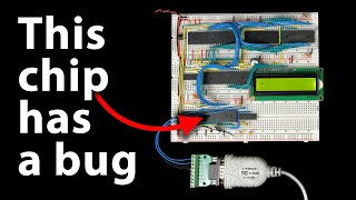
A word of caution regarding the W65C51S parts. There’s a horrific silicon bug where the transmit buffer empty bit is stuck. Earlier versions of the datasheet mention this but the current version tries to sugar coat this issue. Shame there’s nobody else (that I’m aware of) making this otherwise very very easy to use part.
That made me scratch my head for a long time until I found that info in forums. If I remember correctly, that makes interrupt driven data transfert useless. We are stuck with polling mode.
@@NicolasGasnier more precisely, not only is Interrupt driven mode useless, but polling won’t tell you either. You have to wait however long it takes before just going ahead and transmitting the next byte.
Good to know. Might opt for the USB to UART cable using FTDI components to bypass this issue?
And older Rockwell parts didn't have this bug… Hard to find a currently produced chip to replace the W65C51 though.
@@rafalklepinski7372 That wouldn't help. The problem's with the UART itself, not the level conversion side.
I really appreciate Ben's teaching style of showing the simple or nieve solution first, and then diving into the more efficient and reliable solution. You get an idea of how the thing can work at a basic level, before showing you the limitations of that implementation and then showing the better way.
Only Ben can make a 20 min video fly by as if it was a 2 min video
There is never enough Eater videos!! This series is awesome to see how everything’s built together.
I remember dealing with all of these address locations when setting up hardware on pre-PCI, pre-Plug-And-Play PC clones, making sure you didn't have conflicts between your 16550A UARTs and your Adlib sound card and your whatever else. I had a solid _functional_ understanding at the time, but it's fascinating to learn what all of this stuff really meant. I would have loved for these videos to have been available to me back then.
I had the same task when I hooked up 2 6821 to a Z80 via the edge-connector on an Amstrad computer.
I always appreciate the little mistakes that are left in, and showing the fixes. Your videos are wonderfully soothing and informative, like Mr. Rogers or Bob Ross teaching electronics.
YES!! Thank you so much, Ben. I have learned so much about computers through your series, things i just could not wrap my head around before now make perfect sense. Looks like we have a new 65c peripheral chip to play with, I had a nightmare getting the 65c02 and 65c22 in WDC form, had to get rockwell versions instead from ebay.
I've always found them to a be available on Mouser. Hopefully I wasn't just lucky but they've always been in stock when I checked.
4:04 “supposed to have a bar over it but the bar kinda fell off” 😂
Absolutely perfect timing. I just got the MAX232 chip in yesterday, and was about figure out the the uart on my own today. Super excited.
I love these videos. My breadboard routing never looks as good as yours.
Finally! Got my hardware working at 0x7000, however the software does not work - not even loopback. My friend and I are looking forward to see how you handle it. Thanks, Ben.
For a moment there, was thinking...that's an expensive kit. I have only just woken up though
@@daviddawkins me too I was really confused 💀
@@daviddawkins hah😂 same.
It says on my app that this was posted 7 days ago, but the video was released 50 minutes ago...
TH-cam is broken again. Yay.
@@starlii10 He probably makes it available to Patreon members early.
You are amazing!
Great episode! I like the parallels that can be made between your simple addressing circuit and the disjointed address blocks it creates, to the same type of addressing when eg programming for NES! (it is a 6502 as well after all, haha)
At 20:40 we can see your bus wiring is indeed getting untidy and hard to make sense of (even for you!), perhaps it's time you use the amazing trick with power-rails-as-bus you showed us for your computer-from-scratch series?
Excellent stuff. I kind of wish you'd left the mistake in place and tried to use the system though. I think there's a lot of value in that, for us to look at the weird behaviour and try to figure out what might be causing it, and to see how the process of debugging and troubleshooting this kind of thing works. I can imagine people getting one of your kits, hitting this kind of problem and then being totally stuck and discouraged because they haven't seen anyone successfully work through a situation like that
Someone pranked Ben Eater by sending him a Big Endian UART, rather than the standard little endian kind? (Not really, since the status registers would also be backward, but it'd be so tempting to guess the serial data was configured backwards rather than all the parallel lines being wrong.)
Ben the little triangle within the device block more usually means the pin is an edge triggered input.
I assume he meant to put it outside the package, since that's how inverted signals are represented in IEC logic symboks
Thanks
Genuinely always feel a sense of loss once I finish one of your videos.
Please keep making them Ben.
Your public adores you
I was really looking forward to this! Thank you!
Hi Ben. I have been a hobbyist for almost 50 years and a professional electronic engineer for almost 35. I have enjoyed your videos because they go right back to bare bones. I use MCUs these days but I wonder if I would be able to understand embedded issues as well as I do, if I had not been a professional learning through the era of MPUs and discrete peripherals.
While I am loathe to make a criticism as small as this one is, I'd like to point out that it is not a good idea to tie two pins of a NAND or NOR gate together to realise an inverter. The reason is that the internal propagation time to each leg of the gate may vary in time, if only by pico-seconds. This can result in a glitch during transitions. Always best to tie one leg of a NAND gate high and use the other as the input to the inverter. That way there can be no race condition. Likewise, when doing the same with a NOR gate, tie one leg to ground and use the other leg as the input to your inverter.
I watched your peripheral driver videos for the USB, the I2C & the SPI bus. Having written drivers myself, I felt you explained these very well. If you have have time perhaps you could try the 1-wire bus. I have never had the need to write a driver for these but there are still plenty of peripherals for these such as RTCs, memory devices and sensors such as the ubiquitous DS18S20 temperature sensor.
Keep up the good work👍
A spurious high/low on the order of ps doesn’t matter in these asynchronous control lines working on chips with 10s of ns hold times on a 1 MHz system.
There’s a much bigger timing issue if that’s a worry: some chip select line is direct from address line a15, some other has a 1 gate delay, and another has 2 gate delays. Also the clock signal distribution with different length signals creates a clock skew, perhaps on the order of ns.
And of course the whole no-signal-return-path issue.
Tying one input to high/low would lower power consumption for CMOS chips though.
Ugh, I dislike how snarky I come across writing this, sorry.
I was just seeing when you last uploaded and I was like "shit it is only a couple of weeks so he is not uploading anytime soon" but here you are spoiling us with frequent uploads
Its great seeing you upload again
I can't wait to watch this. I knew wayyyy too much about serial connections back in the day. Kermit, SLIP, SLIrP, making clamshell connectors and putting the pin in the wrong place... GOOD TIMES!
Null modems, guessing games around DCD, CTS, DTR, DSR... yup, fun and games 🙂
@@RogerBarraud In my early work days, when everything was still RS232 versus Ethernet, I was the goto guy on-site when folks had trouble connecting device 'X' to device 'Y'. Lot of good that skill does me now... lol. Unless you are building a project like Ben's... and then it all comes back. Hmmm... Where is my HP4951C?
I hooked up my 6551 to the 6522 chip to take advantage of the IRQ functionality. I've implemented my MAX3100 UART directly though. I understand using the WDC 6551 chip for teaching purposes but I highly recommend looking into other options.
Wish we had this instructional videos when I was playing with my Commodore 64. I got into industrial control in school and PLCs. Which was a good career but never really understood the component level stuff as far as processing goes. Thanks Ben for helping me understand.
the day ben eater uploads a video is a happy day
Thank you so much for clear and valuable lessons.
Such nostalgia. I had to write a UART controller for an embedded system, long, long ago.
I'd love to see how neatly you would solder all of these chips onto a perf board. Clearly your wire game is top notch.
back in the early 80's when my main computer was a TRS80-M1 I got into BBS's and used my cassette port to talk to the modem without a UART. I remember writing my own version of the terminal program (wanted to support more vt100 type codes than the Tandy one did) and it was very eye opening about how tight the timing had to be, and this was for the much slower 300 baud speed, which gave me 'nearly' but not quite enough time to refresh the screen.
Figuring a way to scroll the screen in a 'multitasking' manner when you didn't have enough time to move the 1024 bytes that made of up the memory mapped screen, in the 1/300 of a second available. Finding the tech specs on the exact clock ticks each instruction required was a critical part of that project.
See guys, just when you thought it was difficult. Now all we need is to get Ben to take a look at our respective economies. This channel is pure paracetamol.
This takes me back to my computer engineering grad school days back in the early 90's. Good times.
This type of videos need extreme research. Keep it up ben ❤
It's a pity that this channel uploads so few videos, they are of great quality I love them
If only I could obtain the different WDC chips locally in South Africa.... With a non-functional post office, importing them are SO expensive via courier services. Great video as usual, thank you Ben.
Amazing content as always! Thank you!
I like your videos a lot. It's my zen moment of attention.
Amazing how many ways there are to notate active low signals... I've never encountered the B but quite often one that you didn't mention: a lower-case n after the signal (like CSn). For "negative", I presume. Also, I think that the triangle that you mention denotes a clock input, or maybe generally any edge-triggered input.
'n' is usually a prefix.
There's also the '*' convention (usually a suffix IIRC).
I usually use the n-prefix for my own stuff... it preloads my mind with the idea that the following thing is inverted... rather than modifying something that I first read as uninverted 🙂
YMMV...
I never really fully understand your videos but i try my best to rewatch it until I do
Direct Memory Access is such a big word now for gaming but it probably was so common on these kinds of systems, wow.
I think DMA became a thing in the 16bit era, not 8bit systems like this
DMA was a big thing with the Amiga in the 80's
you kinda got this backwards. DMA was uncommon for cheap microcomputers in the 80's, and nowadays, pretty much every single CPU comes with DMA.
DMA isn't Microsoft's DirectStorage API (which is the thing gamers care about), but perhaps DirectStorage makes use of some form of DMA.
@@gower1973 8bit Gameboy Classic had DMA to transfer sprite data. But this console was released rather late, in 1989
New videos from Sharman and Eater on the same day, wow!
Ben looks too young to remember things like the Western Digital WD1402 or Intersil IM6402 - and should account himself thankful! (Using those was a little squirrely - but certainly beat tweaking trimmers for the LC-controlled receivers and transmitters that preceded them! I remember the Western ad in places like Scientific American: "We uncoiled the data transceiver!" (No inductors in their design...)
I did a software UART on one of the smaller Atmel devices not too long ago (short on I/O pins and board space), but simplified things some by using a 9.216 MHz crystal so that the CPU clock divided down nicely to the bit rate. (Still a PITA.) The PIC didn't need to be doing anything else when it was exchanging data, which were just 18-byte messages, so they were pretty quick. (Should probably just have put a CPU core and a UART on a FPGA)
Who's Sharman may I ask?
James Sharman runs a similar channel where he's been building an 8-bit pipelined CPU from scratch. He also uses surface-mount components on in-home designed PCBs. Ben gets you to where you understand it, James runs the advanced class.
@@sirnukesalot24 Also check out FoxTech and his 486 Breadboard Computer.
@@ciano5475 Yeah, I saw that. I'm already following FoxTech just like you are. I think most of us knew he was going to need that fourth bus transceiver no matter what.
With this amount of devices, I would do this: as you described in a previous video, use an eeprom as a logic gate.
Input all address lines into the eeprom, and the output data lines all function as chipselect lines for all of your devices.
This will scale a little better, and will also prevent situations in which multiple devices are fighting over the bus!
Not to forget the small 'n' prepended to a pin name also being used for active low pins :)
Finally new video love your vids
Yes ben keep us mesmerised thank u
The best thing when I see ben uploading
Your passion for this "ancient technology" never gets old. I'm so glad you're seeing this through for/with us!
Ben Eater uploads at the same time as James Sharman? Today is my lucky day
You could of course prevent the 7000-7FFF address waste by checking the two conflicting bits with an AND gate, if it returns 1 you disable both the VIA and the UART to enable another device you may later add into that address space to be enabled on its own.
Wake up babe new Ben Eater video dropped
Hooking my brain up to that would get me fried More seriously we need to discover the max232 max233 max2323 chips and limitations in the next video and hooking up non voltage tolerant devices to rs232
Great video
It's odd - technical but therapeutic, could listen for hours. Lyrical bytes
Great stuff as usual. I cant figure out when the video was posted but looks like recently from the comments. What comes next? Connecting monitor and keyboard?
What about a 74HC138 for I/O address decoding? This its help even the LCD display could be connected to the data bus directry.
And just a warning: The /SO input of the 6502 shouldn't be left floating or the overflow flag could be set randomly in the P register.
WoW another Ben Eater's magic uploaded
Ben Eater rules!!!
The 6551 appears to be easy to use, but they were made by multiple vendors and each version has different requirements to the clock circuit and often those do matter. Feeding it with an external oscillator resolves that. Its timing requirements are easy to meet when driving it with a 6502, but trying to use a different CPU may be difficult and trigger weird bugs, like a stuck transmitter ready bit. Interestingly it is always stuck for the W65C51N and even documented as such.
That mistake in the wiring you caught... Heh.
A while ago I mounted a rpi in a cabinet that contained contactors, sometimes when they switched they generated an rf pulse big enough that the rpi would detect it and include it as an input.
The damn thing worked fine on my desk, in the cabinet... It went haywire. Eventually rather than trying to add shielding or any of that and since the pulsed were so short in duration I just modified the code not to accept inputs that happened faster than a certain time frame.
Biggest head scratcher I've had for a while.
I bought a daisy-wheel printer for a "parts" price because it was continually "blowing" an on-board fuse. I took the fuse wires out to an external fuse holder and began experimenting. After a while, I realised that it was blowing the fuse whenever the AC powered cooling fan switched off after cooling down the print head following a long session of printing. I added a mains-rated 0.01 microfarad capacitor across the fan and suddenly there wasn't a problem. Sold the printer later for a huge profit.
Ben NEEDS to add an NTSC or PAL TV signal for this!
I had to work on a microcontroller that we had to "bit bang" serial comms... you're right, it's very touchy.
As shown @15:53, the decoding logic does not prevent a conflict between the ACIA and the VIA when the high 4 bits are [0111]. A better address decoding scheme would have been to use [010x] for the ACIA, preventing this bus conflict. Sure, you wouldn't normally address the conflict range, but why allow an errant software glitch to cause a hardware conflict when you don't need to?
LOL - I paused literally seconds before you covered it.
Great video! The talk about bus arbitration got me thinking: is there a chip that basically halts the 6502 for a couple cycles while other chips request/write to the RAM? Or maybe something can be done with interrupts and a few gates? 🤔
I'm likely missing some edge case that complicates this, but it sounds fairly simple in principle
The 6502 has a Bus Enable pin, which, when low, causes the 6502 to set its address and data buffers and the read/write pin to high impedance.
The Atari 8-bit computers function along those lines, with the Pokey chip (mainly responsible for video) halting the 6502 when it needs to read memory. That's why you can't reliably judge time by processor cycles unless you disable Pokey (giving you a blank screen).
excited for a new ben eater video
Fascinating!
"RS232 interface with the 6551 UART"
ah yes, those truly sound like some symbols I'd enjoy!
They also used to use an asterisk for active low indication.
I like how simple it it to do the memory decoding, in the Z80 is a bit harder but it has the advantage that it activates two control signals, one to access memory and one to access IO, In my case for the memory decoding I use a 74HC139
The Z80 has the small advantage that you have 256 I/O ports on top of the 64K memory addresses and they don't share the same memory space. An undocumented feature of all Z80 CPUs (so far as I know it's all of them) means that you can also access up to 64K I/O addresses instead of only 256. The instruction OUT (C), A functions as OUT (BC), A which means that if you load a 16-bit address into the BC register pair and then use the OUT (C), A instruction, it will put the full 16 bits from the B and C registers out on the address bus. The same for the IN A, (C) instruction.
Most hardware engineers never took advantage of this feature, either because they didn't know about it or because it was undocumented and they feared it might not be supported in some versions of the Z80.
@@melkiorwiseman5234 Yeah I was aware of this, wich is great, but I don't know why they didn't directly say in the datasheet that user could access 64K IO addresses.
I needed this 3 to 4 years ago, I struggled so much to make something work with uart and rs232
He is a legend.
Hi, I think you might have made a mistake. You connected PHI2 pin on the UART direct to the system clock. I think this should have been connected to the PHI2 output pin of the 6502. The PHI2 pin is the delayed system clock that the 6502 outputs to assist peripheral devices with clocking data on/off the bus correctly.
Your layout may work but it might be a bit flakey.
P.s. love the videos, especially the one on USB!
I hope that when you come to add storage you'll use PATA with a CF card rather than SD/SPI that everyone else uses. It's dead simple, especially if you just ignore the upper 8-bit and only use 50% of the device!
People in the comments who have built this and then tried seem to not getting it working, this could indeed be the issue. Nice catch.
thank you ben
I would have understood this in half the time if Ben was my teacher.
If you've posted it tomorrow, would it be Ben Easter?
Thanks for the chuckle
Hello there! I really appreciate the content you post as a embedded systems grad student, it would be helpful, if you can get some videos on communication protocols!
Hurray! It's a new video
This is great.
But at this point maybe a decoder for the 4 most significant bits would be the way to go
It's a small thing, but thank you so much for referring to address 0x5000 hex as "five zero zero zero", not "five thousand"! That bugs me so much with other videos, since "thousand" is a specific amount and that's more like *twenty* thousand. I never have the heart to correct people about it though, so i'm just glad whenever someone says it correctly!
What’s incorrect about saying five thousand?
What do you mean by “amount”, how is that relevant in this case?
Fantastic
i guess producing a bar over text was not so easy back in the day so they chose to use / instead
Ben's new video out, get the popcorn out. What.. only 22mins? :(
If you have lots of different IO ports what about using a small eprom to decode? I always planned and wanted to build my own computer (probably a Z80) but so many projects and so little time. So watching you doing it (and others) is the next best thing. Really enjoy your videos
No need for an EPROM - address decode is pretty simple. Ben just didn't want to spend the board space on a demux and address comparator. In the old-school TTL he's working with, it's still just a 2-package solution.
@@Shonkyretro Yeah. The people who try to replicate 1970s minicomputers with modern IC's tend to overlook that, but the DEC, Data General and Wang machines all had PALs (no GAL's yet!) here and there.
Of course, the simple GALs are all going obsolete fast. I probably need to get tooled up sooner or later on the bigger CPLD's even though they seem like total overkill.
A single ‘138 would be faster and use less board space than the current NAND solution, without adding any complexity IMHO.
Did I miss you connecting E / PHI2?
It won't work too well without that...
I probably blinked or got distracted though.
People in the comments asking why it doesn’t work when they’ve built and tried it like this, you’re probably onto something.
This is basically a simpler, larger version of s modern microcontroller. That's very neat.
This is all very interesting - especially since this is what I was doing in about 1988! I gotta wonder why in 2023 you're still doing it with the power and flexibility of PICs
I can't speak for Ben, but I find it way more approachable to build stuff with old chips, mainly because they have way better documentation.
Raspberry Pis and Teensys are cool and powerful, but getting a complete list of MMIOs and assembly instructions is a pain, if not basically impossible due to legal constraints. So if you run into a weird bug or edge case, you basically have to trial and error until it works, or give up
The closest a modern cpu chip has come to well documented that I've seen is the PROP2, which is versatile and cool, but hardly on par with modern microcontrollers
On top off that, the Pis have closed source boot loaders, which means no matter what you make you still rely on a black box of code doing who knows what on the GPU for a couple seconds at startup. This isn't usually a big issue, but if your trying to minimize boot time, you eventually reach the point where the biggest delay is something you can't even look at
I'll certainly stick to modern chips and tools when doing most things, but underdocumentation gives me anxiety. any time I run into an issue that the docs don't explain, I worry i may just have wasted my time and can't move forward. Usually there's answers out there, but sometimes the answer is "you can't do anything about that"
Because this is how you learn the fundamentals!
The same reasons that there are many people who still learn thousands of other skills by hand / manually / the old fashioned way.
Usually for the appreciation for older technology, better understanding of hardware fundamentals, enjoyment of a slower process and many other reasons.
Sure you could use a PIC or an AVR microcontroller or even a 32/64 bit ARM device with built in uart and high level programming language and do all this in about 10 minutes but it isn't the point.
Something like the CH32V003 which has a list price of 8-20 cents is a 32bit RISC design with built in UART/I2C/SPI and 18GPIO/10ADC ports throw in the cheapest lcd and breadboard you could probably build the thing for under $5.
Wouldn't learn anything about how the hardware actually worked though nor how to program it low level.
I like where this is going! 😁
I once had a USB port on my laptop stop working; I think it was because of a serial killer...
And my wife passed me my breakfast through the pass-through over the kitchen counter. It was a cereal port.
@@ke9tv LOL!!!
Great as usual! I hope you will describe the CPU usage doing a simple loop instead of using events or interrupts.
Ben, did you actually notice the cabling mistake [D0..D7] when you intended to bend the cables and felt they did not bend correctly? Like muscle memory triggered you into checking the order of the connections? It certainly looks this way when watching this (yet again) excellent video of yours.
I like the slash in front of the name if an overbar isn't possible. I've never seen the notation with B at the end.
You could also use one of those ram chips that has two interfaces that can be used at the same time. With it writing to side B while the rest of the system is on side A.
When you say I guess, it means sure and when you say may be it means confirmed . This is Ben eater dictionary!
Hey Ben, love the video, built my own computer based on your videos! Are you planning a video on I2C? Would be very interested in that!
Super bhai
Arrr..., have so much trouble with RS232 and Cisco-Consolecable.
Have a LoRa-Microcontroller, and want serial out as a fallback to switchconsole.
But it seems that cisco doesn't follow this standard
Memory Mapped I/O, bro!
You ever plan on covering HDMI?
BTW love your content!
Considering how well suited the keyboard protocol seems for RS232 I find it kinda odd that there seem to have been almost no keyboards with an ordinary DB9 serial port, even though there where lots of serial mice back in the day.
PC keyboards always seem to have used a DIN or mini DIN connector until everything became USB. Why is that?
Maybe, it's because computers may have more than only one "ordinary" serial port and they wanted to make sure the keyboard is connected to a specific port (using a connector that doesn't fit anywhere else). That makes it easier for the BIOS to handle keyboard inputs (especially back when memory - including ROM - was expensive and you'd hard-code things like that rather than wasting memory just to detect what physical port the keyboard is connected to).
The DB9 interface also doesn't offer a supply voltage to power anything connected to it. Having a separate power cable (in addition to the data cable) to supply the keyboard or just drawing current via the (unused) signal pins (what serial mice usually do) isn't a nice solution either. Early PCs didn't come with a mouse and weren't "designed" with a mouse in mind. A serial mouse came later as a "cheap" solution you could add to something you already had. But there were also mice that came with expansion cards to be installed into the PC.
Would it make sense to use a 74ls138 now that the address decoding is getting more complex?