I doubt that anyone will ever see this post, but I had to write one because this video is the BEST I have seen regarding this subject. I have been looking for this solution for over 6 years now and came across it just now. Every other video on YT does not use position control with DC/encoder control(closed loop). Seems they all like steppers. There is no better way than this method for position control at a very inexpensive solution. I was a CNC tech for over 25 years, and this method was used long ago on industrial machining centers. Thank you very much for this project!
Nikodem, you're sooo diverse! It's always fun to see what you're tinkering with each video! Your projects always intrigue and impress me! Keep up the great explorations and work!
I think you should zoom in on the code when you're explaining it, now it's a bit hard to see on a computer and on mobile it's impossible. Otherwise cool video!
Nice tutorial! My actual project for agriculture uses a sensor hall or a reed switch to control a peristaltic pump. The "IN" is the wheel speed. It uses a 12V, 36W windshield motor and a IRF1404 “as driver” (plus a diode and resistors for protection).
Great tutorial. This is precisely how I want to control my droid dome rotation. Remote controllable and automated. Thank you for all your research. Gotta get myself a 12v dc motor with encoder now. ;)
Do you have a correct circuit diagram for this? The link you included for the motor has a harness with the wires in a different color order than the motor in your video. The colors do not match your fritz diagram.
I pulled up the DC Motor w/ Encoder that you provided a link to in the video's details and compared it to the Fritzing diagram you displayed (3:19), and the wiring you suggested does not make sense to me. In particular: Why are we connecting the motor's white "Quad encoder B signal'" wire (see Amazon's pictures) to the negative motor terminal of the driver?
Great video and thank you for the time you invest in these videos. It would be great if you could explain the wiring a bit more too. "Here is the motor... it has 6 wires" - what are those six wires for? My motor has 2 power wires and 4 encoder wires, so it looks different and has different colors but has the same functionality. If you explained what the wires are for, it will help others with different motors to also understand the wiring better.... like myself :-) But thank you again
I connect a 12v encoder motor instead of 6v when I move the potentiometer ligermanet the motor does not respond and keeps rolling why? I send position in serial plotter and nothing it still rolling -85 -87 -88 -90 -92 -93 -95 -97 -99 -100 -102 -104 -106 -108 -111
Can i use an encoded motor as a 360 degree rotation servo ? Suppose i give an input of 5 to the arduino using some monitor display then the encoder must stop at 360degree/5 position, like every 72 degree the motor should stop and rotate??
In your code, you’d be much better off defining a constant for each dio pin e.g. MotorSense = 3; Not only does it make your code easier to read, and less likely to make mistakes, but if you ever changed pin, you only need to change the code in one place.
Great tutorial, I try to run the code with the same setup for both knob and serial, but the motor doesn't seems to run correctly. The motor just run at one direction and with constants speed, even when I turn the potentiometer left to right, or the otherway around. Same thing with the serial version, the motor just run at constants speed to different number I typed in. The motor I have is slightly different than the one you have, but the encoder is the same specs, same color cables with 11 signals for 1 turn. Do you know why? is it because of this line where I have to tune? pos_pid.tune(20, 0, 200); Thanks
I came across this video after having successfully made a project exactly like the one you mentioned 1st, with the potenciometer. However, I tried doing something using serial comm as the source of the target position, but anytime I connect the powered motor driver to the arduino, serial comm doesnt work. I'm left disconnecting the driver anytime I want to type a number in serial comm. All the grounds have a single common ground point, so it's not a grounding issue. A friend suggested it might be electrical noise from the m.driver interfering with the arduino, what dya think? Thanks
Are going to make a video about how to implement this method to a robot with two wheels? I need to learn how to control two motors in synch on my project. Thank you
NIcely done! I'm curious about your inclusion of the PID library. Are you using that to accomplish smooth acceleration/deceleration of your motor? Cheers
Great video! If I understand correctly, the encoder you ultimately used will tell you relative position, not absolute position, is that right? In other words, if you turn the arduino off and then on again, it will think that the current motor position is "0"?
Hello friend, I'm from Colombia, I'm doing this same project using exactly the same components and the same code of your video, but I can't get it to work correctly, when it reaches the position that it should stop, the only thing it does is reverse the direction of rotation , please help me
Hi, thank you for the video! Do you know where i can found this motor's datasheet? I need some values like resistance, inductance, moment of inertia...
You will have a bit of a problem with i2c. The problem will be the interrupt - you will need to make sure you can read pulses while communicating over i2c... What's the problem of using serial instead of i2c, btw? Misun wrote a nice servo controller already for arduino, esp8266 and I modded it for ATtiny85, perhaps check that one out for inspiration ;) Nice work, btw. Good luck.
Thank you for sharing this video. Have you used the LM393 speed sensor with a DC motor? I am facing a problem with this sensor because it overcounts every time when I use interrupts. Can you please make a video on it?
Can I use the Arduino to compare vibration levels of different cd players ect? If so, is it as simple as placing the Arduino sensor on the cd player chassis and also using a multimeter to get the reading?
Hi, do you think is it possible to do a open loop test in order to get a mathematical model of the motor? The test is simply to put a voltage at input and measure the speed output, and of course to hold the data. Thanks
How do you keep the position of the motor same on startup? for example if it is in a robot arm then how do you know the absolute location of the arm on startup. Wont the position be different every time the robot boots up?
yes it will, that's the downside of these motors, more expensive robotic arms use absolute enocoders, that way the position of the motor is always known
Hi! I am a fan of your youtube channel, because they are easy to follow. Can you provide a schematic drawing for the wiring when using Arduino uno instead of nano?
i have same small printer motor with encoder. but i dont know what is the cable order. how can i learn which cable is signal which is gnd which is v5 ??? pleasee helppppp
I entered the code according to the video, but the motor does not stop. The code on GitHub also seems to be inaccurate. What code do I need to write to do the same as 5:55?
Thanks for shareing the core. I was not familiar with coding and I was tring to use the STM32 MAPLE BOARD insted using arduino nano. I just going to change some pin number, But it not work...... the encoded can show up to 7 or some number, then the loop was dead. Any ider with that? Thanks.
hi first of all good work on the video very well made! i am thinking to introduce this motor into my project (replacing my stepper motor) my question is since my motor will have some load on the shaft would you suggest e a better motor driver in terms of heating and idle power handling? for example for the stepper i'm using a tmc 2208 wich drops power up to 20% when idle...hope to hear from you soon keep up the good work!
Hello great video. One question though, I try to type 0 into the serial monitor after typing in 1000 and it won’t go back to 0, do you know why that would be? Thankyou
Thank you for sharing this information with us. I have a question about checking the position when the tree has to stand still. How you manage this and how you implemented the sw to do it.
Thanks for a great video! I'd like to ask a newbie question. Would it be possible to use a quadcopter ESC flashed with BLHELI firmware, as a motor driver for such precise control of a BLDC motor with encoder?
Can you please tell me what type of rotary encoders I need for air manager and how I can connect each I strument to encoders to turn ? Thank you. I told many how made it in youtube but they never told me
hello, this tutorial is quite helpful. thanks for your great effort! I have brought a DC geared motor. it's kinda different than the one you have used but I believe it would serve the same purpose especially that it has the same exact encoder. I was wondering if I could use it on my Arduino mega without a motor drive. please help me! thanks in advance.
Interesting video regarding ardulnos, I'm currently working on a project it's an radio controlled model kayak 🛶 1:6 scale but having great trouble mimicking scaled down body movement like forward backwards left and right with a two standard motor setup using normal standard r/c the timing on the motors needs to be correct as it's critical for the paddle strokes, the system i have at the moment is a electronic speed controler (esc) driving two motors. Just wondering if you can point me in the right direction if it can be done involving an endcoder motors ardulno system working with a r/c receiver and transmiter. Have a look on my channel to see kayak videos thanks Chris.
Hey. Perhaps, for your question, if you search for "JGA-25 370 6V 210RPM with encoder - how to get RPM from encoder pulse frequency", which is found on the arduino forum, or something similar, maybe it can help you, not that it is this is the encoder motor value that the author of the program has used. ----------------------------------------------------------------------------------------------------------------------------------- Oi. Talvez, para essa sua questão, se você procurar por "JGA-25 370 6V 210RPM with encoder - how to get RPM from encoder pulse frequency", que se encontra no forum arduino, ou algo similar, talvez possa lhe ajudar, não que seja esse o valor do motor encoder que o autor do programa tenha utilizado.
My code was working fine but then one fine day when i give a serial input value of 555 the encoder rotates to 5555 idk shy this happens but for any value i give the motor turns to times 10 of the given value. Can anyone tell me what to do?


Support my projects on Patreon → www.patreon.com/nikodembartnik
I doubt that anyone will ever see this post, but I had to write one because this video is the BEST I have seen regarding this subject. I have been looking for this solution for over 6 years now and came across it just now. Every other video on YT does not use position control with DC/encoder control(closed loop). Seems they all like steppers. There is no better way than this method for position control at a very inexpensive solution. I was a CNC tech for over 25 years, and this method was used long ago on industrial machining centers. Thank you very much for this project!
I have seen it :) Thank you very much!
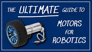
Great explanation of how an encoder works! 0:53
Nikodem, you're sooo diverse! It's always fun to see what you're tinkering with each video! Your projects always intrigue and impress me! Keep up the great explorations and work!
I think you should zoom in on the code when you're explaining it, now it's a bit hard to see on a computer and on mobile it's impossible. Otherwise cool video!
Quality of your videos is really getting better! Keep up the good work!
That background music is really chilling, I like it.
Nice tutorial! My actual project for agriculture uses a sensor hall or a reed switch to control a peristaltic pump. The "IN" is the wheel speed. It uses a 12V, 36W windshield motor and a IRF1404 “as driver” (plus a diode and resistors for protection).
Great tutorial. This is precisely how I want to control my droid dome rotation. Remote controllable and automated. Thank you for all your research. Gotta get myself a 12v dc motor with encoder now. ;)
this is completly underated thx man
SOOOOOOO nice. Love the way you've summed it all up.
nice editing man, i like this.
cool and very nicely and clearly explained.
Do you have a correct circuit diagram for this? The link you included for the motor has a harness with the wires in a different color order than the motor in your video. The colors do not match your fritz diagram.
Excellent production quality!
I pulled up the DC Motor w/ Encoder that you provided a link to in the video's details and compared it to the Fritzing diagram you displayed (3:19), and the wiring you suggested does not make sense to me. In particular: Why are we connecting the motor's white "Quad encoder B signal'" wire (see Amazon's pictures) to the negative motor terminal of the driver?
Great video and thank you for the time you invest in these videos. It would be great if you could explain the wiring a bit more too. "Here is the motor... it has 6 wires" - what are those six wires for? My motor has 2 power wires and 4 encoder wires, so it looks different and has different colors but has the same functionality. If you explained what the wires are for, it will help others with different motors to also understand the wiring better.... like myself :-) But thank you again
thanks, this really helped me
Huge thanks! It was useful for me
2:54 where to buy an encoder like that without the motor? I have 2 peg prego dc motors that I want to put an encoder.
I connect a 12v encoder motor instead of 6v when I move the potentiometer ligermanet the motor does not respond and keeps rolling why? I send position in serial plotter and nothing it still rolling
-85
-87
-88
-90
-92
-93
-95
-97
-99
-100
-102
-104
-106
-108
-111
Nice and useful product. I liked it.
Great video!
clearly explained, thank you !
U saved my life mate! Thank you
it ok for wheel but for a turret we have to know the zero so what kind of sensor allow angle feedback
Files and code link doesn't work
in the link change SmallProjects to Small-Projects
Can i use an encoded motor as a 360 degree rotation servo ? Suppose i give an input of 5 to the arduino using some monitor display then the encoder must stop at 360degree/5 position, like every 72 degree the motor should stop and rotate??
In your code, you’d be much better off defining a constant for each dio pin e.g. MotorSense = 3; Not only does it make your code easier to read, and less likely to make mistakes, but if you ever changed pin, you only need to change the code in one place.
Great video, all works well. Would like to put a micro switch to set the 0 point on start up. do you have any videos on that?
Thanks yo, Wish you all the best
excellent and subscribed!
Very good visuals
Great tutorial, I try to run the code with the same setup for both knob and serial, but the motor doesn't seems to run correctly. The motor just run at one direction and with constants speed, even when I turn the potentiometer left to right, or the otherway around. Same thing with the serial version, the motor just run at constants speed to different number I typed in. The motor I have is slightly different than the one you have, but the encoder is the same specs, same color cables with 11 signals for 1 turn.
Do you know why? is it because of this line where I have to tune? pos_pid.tune(20, 0, 200); Thanks
did you fix it?
I came across this video after having successfully made a project exactly like the one you mentioned 1st, with the potenciometer. However, I tried doing something using serial comm as the source of the target position, but anytime I connect the powered motor driver to the arduino, serial comm doesnt work. I'm left disconnecting the driver anytime I want to type a number in serial comm. All the grounds have a single common ground point, so it's not a grounding issue. A friend suggested it might be electrical noise from the m.driver interfering with the arduino, what dya think? Thanks
How make control without potentiometer, I want use other encoder to control the servo in this project.
Awesome video. Thank you!
Are going to make a video about how to implement this method to a robot with two wheels? I need to learn how to control two motors in synch on my project.
Thank you
Excellent tutorial. Thanks
When using the 2nd version of the code without potentiometer, do you just remove the potentiometer from the wiring schematic?
did you ever figure this out. its driving me crazy. i dont know know what to do.
@@MichaelRHead-zv2zf Niko didn't reply so I didn't go down this path. I found one that was simpler/cheaper th-cam.com/video/yvrpIYc9Ll8/w-d-xo.html
Thank you!
NIcely done! I'm curious about your inclusion of the PID library. Are you using that to accomplish smooth acceleration/deceleration of your motor? Cheers
Great video! If I understand correctly, the encoder you ultimately used will tell you relative position, not absolute position, is that right? In other words, if you turn the arduino off and then on again, it will think that the current motor position is "0"?
Easy and good explained, worth a follow :)
Sorry if I'm a beginner.
I want to ask, is this the same as the stepper?
Can i set the motor to only rotate 2x (for example) ?
nice job!! quick question, how would you have figured out the gear ratio if the motor you have wasn't documented?
Sorry, but I couldn't find right code in your repository. Can you say me file's name for Encoder, please! Thanks a lot for good video
02:25 I have the same motor from a printer. Do you know by any chance where can I get its datasheet?
Hello friend, I'm from Colombia, I'm doing this same project using exactly the same components and the same code of your video, but I can't get it to work correctly, when it reaches the position that it should stop, the only thing it does is reverse the direction of rotation , please help me
In addition, the current when reaching the desired position rises too high and the motor driver gets very hot.
suggestion for a new video of a cnc router with this motor and encoder
Hi, thank you for the video!
Do you know where i can found this motor's datasheet? I need some values like resistance, inductance, moment of inertia...
Do you have a scematic layout for the setup without potentiometer using the digital input, or is the potentiometer still there?
You will have a bit of a problem with i2c. The problem will be the interrupt - you will need to make sure you can read pulses while communicating over i2c... What's the problem of using serial instead of i2c, btw? Misun wrote a nice servo controller already for arduino, esp8266 and I modded it for ATtiny85, perhaps check that one out for inspiration ;) Nice work, btw. Good luck.
Thank you for sharing this video.
Have you used the LM393 speed sensor with a DC motor? I am facing a problem with this sensor because it overcounts every time when I use interrupts. Can you please make a video on it?
Hi. I'm new at this. Can you tell me where each color wires go? It's hard to see from your pic. I have same 6 color wires. Tks in advance.
Thnx for this
Can I use the Arduino to compare vibration levels of different cd players ect? If so, is it as simple as placing the Arduino sensor on the cd player chassis and also using a multimeter to get the reading?
I like it. Could this be made as a drop in replacement for a stepper motor?
With proper PID calibration, it could be used instead of a stepper motor
Hi, do you think is it possible to do a open loop test in order to get a mathematical model of the motor? The test is simply to put a voltage at input and measure the speed output, and of course to hold the data. Thanks
Hi, nice video, how did you manage the motor with the serial monitor?
Thanks
Hello my friend. I have the same small engine in the video. but I do not know the wiring diagram. I will only use the encoder. Can you help me?
How do you keep the position of the motor same on startup? for example if it is in a robot arm then how do you know the absolute location of the arm on startup. Wont the position be different every time the robot boots up?
yes it will, that's the downside of these motors, more expensive robotic arms use absolute enocoders, that way the position of the motor is always known
are you doing research for weather to buy larger stepper motors or servo motors for your large cnc
Hi! I am a fan of your youtube channel, because they are easy to follow. Can you provide a schematic drawing for the wiring when using Arduino uno instead of nano?
i have same small printer motor with encoder. but i dont know what is the cable order. how can i learn which cable is signal which is gnd which is v5 ??? pleasee helppppp
I entered the code according to the video, but the motor does not stop. The code on GitHub also seems to be inaccurate. What code do I need to write to do the same as 5:55?
It sounds like you have the wrong motor polarity. When the motor moves in the positive direction, the encoder must count positive.
Thanks for shareing the core.
I was not familiar with coding and I was tring to use the STM32 MAPLE BOARD insted using arduino nano.
I just going to change some pin number, But it not work...... the encoded can show up to 7 or some number, then the loop was dead.
Any ider with that?
Thanks.
hi first of all good work on the video very well made! i am thinking to introduce this motor into my project (replacing my stepper motor) my question is since my motor will have some load on the shaft would you suggest e a better motor driver in terms of heating and idle power handling? for example for the stepper i'm using a tmc 2208 wich drops power up to 20% when idle...hope to hear from you soon keep up the good work!
Hello great video. One question though, I try to type 0 into the serial monitor after typing in 1000 and it won’t go back to 0, do you know why that would be? Thankyou
Thank you for sharing this information with us. I have a question about checking the position when the tree has to stand still. How you manage this and how you implemented the sw to do it.
it could be possible to do a reverse engineer that method to build a DRO for Manual Mill?
Thanks for a great video! I'd like to ask a newbie question. Would it be possible to use a quadcopter ESC flashed with BLHELI firmware, as a motor driver for such precise control of a BLDC motor with encoder?
I have a problem, if I have a motor with encoder but it handles a voltage of 24 volts, which model of H-bridge can I use?
the l298n can handle it, make sure to see how it works
hello sir can I do it without using potentiometer ?
Can you please tell me what type of rotary encoders I need for air manager and how I can connect each I strument to encoders to turn ? Thank you. I told many how made it in youtube but they never told me
Hello there, can I control dc motor with encoder by 2 line the first one is pulses for steps and the second one is (0,1)for direction?
Is it like stepper motor can use it in cnc
What program do you use to 3D printer designs?
Fusion 360
Can we control position of motor using L293 motor controller??
i can't get it to stop spinning. I can get it to go forward and backwards but it will not stop any help?
Tnx on video, keep them coming :)
How did you connect the encoder's wires?
Good but what pid library are you using ?
this is --> www.arduinolibraries.info/libraries/pid-controller
hello nice work, could you upload the source code, the link u provided is not working..
hello, this tutorial is quite helpful. thanks for your great effort!
I have brought a DC geared motor. it's kinda different than the one you have used but I believe it would serve the same purpose especially that it has the same exact encoder.
I was wondering if I could use it on my Arduino mega without a motor drive.
please help me! thanks in advance.
Interesting video regarding ardulnos, I'm currently working on a project it's an radio controlled model kayak 🛶 1:6 scale but having great trouble mimicking scaled down body movement like forward backwards left and right with a two standard motor setup using normal standard r/c the timing on the motors needs to be correct as it's critical for the paddle strokes, the system i have at the moment is a electronic speed controler (esc) driving two motors. Just wondering if you can point me in the right direction if it can be done involving an endcoder motors ardulno system working with a r/c receiver and transmiter. Have a look on my channel to see kayak videos thanks Chris.
is there already a library avalible?
what pid library are you using ?
please use a bigger font on IDE bro! nice video
Hello, can you tell me the name of the motor controller? Regards
I can’t find the code shown from attachment. The only using PID is 168 lines contrast yours is 40.
why are u have "* 3740" at first line in void loop? Thank u!
Hey. Perhaps, for your question, if you search for "JGA-25 370 6V 210RPM with encoder - how to get RPM from encoder pulse frequency", which is found on the arduino forum, or something similar, maybe it can help you, not that it is this is the encoder motor value that the author of the program has used.
-----------------------------------------------------------------------------------------------------------------------------------
Oi. Talvez, para essa sua questão, se você procurar por "JGA-25 370 6V 210RPM with encoder - how to get RPM from encoder pulse frequency", que se encontra no forum arduino, ou algo similar, talvez possa lhe ajudar, não que seja esse o valor do motor encoder que o autor do programa tenha utilizado.
project gonna be opensource?
You need more zoom on code display
and a little more explanation code plz
btw Fantastic Video Thanks Great Job
My code was working fine but then one fine day when i give a serial input value of 555 the encoder rotates to 5555 idk shy this happens but for any value i give the motor turns to times 10 of the given value. Can anyone tell me what to do?
Thanks. Can you share me PID controller library?
Is it possible to know the position after a poweroff?
For that you need an absolute encoder
@@nikodembartnik thank you. I will look into that. I was thinking about homing with a HAL sensor after some research tonight :).
if you also connect AS5600 contactless angle sensor check
what the chances of you showing the code but with an rc control?
Hi sir can you please make a vedio on home made servo motor
I have some Idea by it is not working please help