Werewolf Wu, good job on the explanations. I am also pleased that I am not the only one who hates it when manufacturers and individuals fail to follow the rules for upper and lower case letters when showing metric values. I even worked with a company for several years where the engineers knew better, but the company 'hard rule' was that all printing on drawings and stamped onto products MUST be in upper case, so milli always became mega, etc.
I built a "very analog" LED bargraph water level indicator. (A vertical pvc pipe set-up with 10 reed switches outside "encapsulated in silicone" inside the 1' pvc pipe a Styrofoam float with a neodymium magnet on top) Besides the disadvantages of a myriad of wires (I used cat6 cables) the water would eventually seep through the silicone and cause "erroneous readings" This will help me set-up a single wire pair to the sensor, now I will have to figure out what IC to use to feed the LED bargraph. Thank you so much! 😊
thanks for making this kind of videos, I am working with pressure sensors from 0 -15 Psi, and they return me from 4 -20 mA. This information will be very helpful to connect it to an Arduino MEGA 2560, Thank you for helping me and I will be following you to see what more content you make. Thank you.
I used a large 2watt 222ohms resistor as shunt and 12v (most sensors work fine even with lower voltage), placed a current limiting 10k resistor between the analog Pin and the shunt, this will protect the arduino and is short safe. If you add a 6.8v zener from analog Pin to ground, it can also cope with 24v. Hope this helps.
Thanks! Thanks to your video i was able to hook up a 16Bar pressure sensor to my arduino. For some reason my pressure was running from 4mA to 12mA full scale. Also first time i measured 2mA with 0 pressure, after having applied pressure 1 time , funny enough it showed 3.95mA when no pressure was applied. So then it was working as expected. But the max stayed 12mA. The same sensor PT506 exists also in a 25Bar version, maybe they mislabeled mine? However after changing the formule it worked like a charm and the Arduino showed what i was reading on the pressure regulator. Thanks your video was awesome and clear and helped me how to connect 2 wire sensors. So i learned something new. Much appreciated!
Glad you found it useful! Hope you are successful with your project! I'm incorporating these sensors into my 12,500 gallon rainwater collection project right now.
@@werewolfwu In my case, I am designing a Personal Weather Station, the anemometer and the vane both are 4-20mA. Your video helped me a lot to understand the hook-up and calculations, etc. In the meantime, I am using a 4-20mA simulator to get the calculations right before hooking the anemometer and vane, for example, the vane at 8mA (25%) should indicate 90°, at 12 mA (50%) 180°, etc. You are right, in my case, a 160Ω is the magic resistor value for a 3.2V ESP32 Controller. Here is one problem I solved after I watched your video: I was using two power supplies, one for the ESP32 and one for the 4-20mA simulator, that did not work because the grounds MUST be all connected together. I scaled down the 12V to 5V for the ESP32, same ground all over, bingo! Problem solved. Once again, thank you. Happy new year!
@@ChristianGrau92 Hello! Sorry for the late reply. There are only two wires connected to the sensor: red and orange. The best way to internalize the working mode of these sensors is to treat them as "smart" resistors, that adjust itself so that the current flowing through them "happens to" scale perfectly with whatever they are sensing. The common arrangement of "red for power black for ground plus some signals" does not apply to these sensors. Hope this helps!
Hello Diego: if your sensor is a resistive one, it is definitely NOT the same as 4-20mA sensor. You can still use a similar circuit as shown with minimal modification: simply form a resistive divider with your sensor (which is a resistor) and another resistor (say around 100ohms), and sense the divided voltage compared to the reference. This way you get the ratio between the resistors, and hence the resistance value. A little math is needed but not too hard.
Which specific aspect of ADC? Perhaps I can help you out in the comment section first. Let me know what you'd like to know about ADCs. We'll see who answers it better: human or AI.
Yes! It's amazing that if you search for LCD screens with i2c for Arduino on the internet, there's pretty much only one kind of model that's available, perhaps with different sizes. And that's what I'm using. I actually don't know what I should call it. I only know that all the sellers sell the same thing and all the libraries that you can find in Arduino are actually just slightly different from each other!
Thanks for the video,I have built the same circuit with a water flow sensor, but the output signal has a fluctuation.how can i fix this problème i used ESP32
Thank you so much for your video with a good explanation. I am also working on getting data from the industrial sensor but not getting the same data as the sensor display shows. Could you please help me with it without LCD? Thank you in advance.
It's a generic module that I bought off Jeff Bezos' establishment. Similar things can be found on all sorts of online retailers, simply search for "5V to 24V converter". Required power level is low, a 50mA output capacity (or higher) is enough.
Hello Darragh: What you are asking for is essentially the output portion of an actual 4-20mA sensor. There are many ways to create a current source with digital control. e.g. a current DAC or a voltage DAC with a regulating feedback loop etc. If you don't need a lot of resolution, you may want to look at something like Max5550. If you do require a lot of resolution, search for "16 bit current DAC" and there are tons of options out there.
My humble suggestion would be to use some kind of USB to I2C/SPI converter to control the current DAC on your dev bench. This makes the development easier. Once you have the control of the DAC verified, you can code that into an Arduino of sorts if your application requires it.
Hello! I have a Differential Pressure Transducer (Setra M260 Multi-Sense) and I want to read its output value using Arduino. Can you help me with the code if possible? Thanks! I'm looking forward
I'd imagine one approach is adding a 0% offset in the mA to % equation. Thought it would help to know if the equation slope is off or if its y-intercept issue.
I would politely caution against using 250Ohms for 5V operation: the "5V" on Arduino is often QUITE OFF from 5V. E.g. if the "5V" is actually 4.5V, you'll lose quite a bit of measurement range. In my very humble opinion, it is much better to have a little bit more quantization noise than losing a chunk of measurement range.
You keep blaming the "$40 sensor" when it's more likely your measurement accuracy that's at fault the Arduino ADC isn't particularly accurate/linear and has pretty poor resolution you'd usually use a proper 4-20mA interface IC but even then you still need a decent ADC. Another useful feature of 4-20mA loops is fault detection, you can tell if the wiring is short/open circuit or if a service tech didn't plug it back in properly.
Assuming you put the sensor in a tank and the height keeps changing when there is no water change (water addition or substraction). What could be problem if you are using a 24v battery
Hello GRM Central Kenya TV: If your reading keeps changing while the water level is not changing, then I would start by swapping out the sensor... :-) These sensors are enclosed micro computer systems, it's quite possible to be broken...


Werewolf Wu, good job on the explanations.
I am also pleased that I am not the only one who hates it when manufacturers and individuals fail to follow the rules for upper and lower case letters when showing metric values. I even worked with a company for several years where the engineers knew better, but the company 'hard rule' was that all printing on drawings and stamped onto products MUST be in upper case, so milli always became mega, etc.
Mega Amps!
I built a "very analog" LED bargraph water level indicator. (A vertical pvc pipe set-up with 10 reed switches outside "encapsulated in silicone" inside the 1' pvc pipe a Styrofoam float with a neodymium magnet on top)
Besides the disadvantages of a myriad of wires (I used cat6 cables) the water would eventually seep through the silicone and cause "erroneous readings"
This will help me set-up a single wire pair to the sensor, now I will have to figure out what IC to use to feed the LED bargraph.
Thank you so much! 😊
Glad you found it useful!
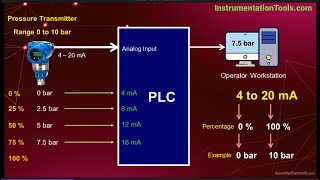
thanks for making this kind of videos, I am working with pressure sensors from 0 -15 Psi, and they return me from 4 -20 mA. This information will be very helpful to connect it to an Arduino MEGA 2560, Thank you for helping me and I will be following you to see what more content you make. Thank you.
Hello Paco: glad you found it useful!
Have you took a trail with pressure sensor with ardunio mega. Is it showing correct feedback? Please reply.
I used a large 2watt 222ohms resistor as shunt and 12v (most sensors work fine even with lower voltage), placed a current limiting 10k resistor between the analog Pin and the shunt, this will protect the arduino and is short safe. If you add a 6.8v zener from analog Pin to ground, it can also cope with 24v. Hope this helps.
that is quite a big resistor physically
Thanks! Thanks to your video i was able to hook up a 16Bar pressure sensor to my arduino. For some reason my pressure was running from 4mA to 12mA full scale. Also first time i measured 2mA with 0 pressure, after having applied pressure 1 time , funny enough it showed 3.95mA when no pressure was applied. So then it was working as expected. But the max stayed 12mA. The same sensor PT506 exists also in a 25Bar version, maybe they mislabeled mine? However after changing the formule it worked like a charm and the Arduino showed what i was reading on the pressure regulator. Thanks your video was awesome and clear and helped me how to connect 2 wire sensors. So i learned something new. Much appreciated!
Glad you found it useful!
Thank you for your well-explained video about a 4-20 mA sensor hooked to an Arduino.
Glad you found it useful! Hope you are successful with your project! I'm incorporating these sensors into my 12,500 gallon rainwater collection project right now.
@@werewolfwu In my case, I am designing a Personal Weather Station, the anemometer and the vane both are 4-20mA. Your video helped me a lot to understand the hook-up and calculations, etc. In the meantime, I am using a 4-20mA simulator to get the calculations right before hooking the anemometer and vane, for example, the vane at 8mA (25%) should indicate 90°, at 12 mA (50%) 180°, etc. You are right, in my case, a 160Ω is the magic resistor value for a 3.2V ESP32 Controller.
Here is one problem I solved after I watched your video: I was using two power supplies, one for the ESP32 and one for the 4-20mA simulator, that did not work because the grounds MUST be all connected together. I scaled down the 12V to 5V for the ESP32, same ground all over, bingo! Problem solved.
Once again, thank you. Happy new year!
That sounds like a great project! Interfacing with the real world and all! Happy new year to you too!
Thank you for the video, it is very helpful. I am working on connecting the same sensor to an esp32 and this helps me a lot.
Glad you found it useful Silas!
Thank you so much, i have been looking for this exact info a long time! Finally i maybe can use this to get my remote readings with a 4G simcard board
Glad you found it to be useful!
@@werewolfwuCorrect me if i'm wrong but didn't you miss a black cable in your picture of the drawing going from the 24v to sensor?
@@ChristianGrau92 Hello! Sorry for the late reply. There are only two wires connected to the sensor: red and orange. The best way to internalize the working mode of these sensors is to treat them as "smart" resistors, that adjust itself so that the current flowing through them "happens to" scale perfectly with whatever they are sensing. The common arrangement of "red for power black for ground plus some signals" does not apply to these sensors. Hope this helps!
is it the same way when using a magnesense pressure sensor?
should be!
Thank you very much, great video, greetings for you from Algeria 🇩🇿
Thank you! Glad you found it useful!
If my tank level sensor is a resistive sensor (240-30 ohms) its the same as 4-20mA sensor system?
Hello Diego: if your sensor is a resistive one, it is definitely NOT the same as 4-20mA sensor. You can still use a similar circuit as shown with minimal modification: simply form a resistive divider with your sensor (which is a resistor) and another resistor (say around 100ohms), and sense the divided voltage compared to the reference. This way you get the ratio between the resistors, and hence the resistance value. A little math is needed but not too hard.
How we isolate the microcontroller from the sensor side?
Hi Werewolf, thank you for sharing such a good content. Btw, do u have the follow up topic on ADC? Thank you!
Which specific aspect of ADC? Perhaps I can help you out in the comment section first. Let me know what you'd like to know about ADCs. We'll see who answers it better: human or AI.
Can you make a video connecting Pixsys on a pressure sensor please?
Hi, thank you for detailed explanation. Do you have idea how can we wire two (or more) sensors like this? How to isolate inputs? Thank you.
You would need one power supply and 2 return paths to carry two signals.
Thank you for your video. Would you be able to provide the model of LCD display you are using?
Yes! It's amazing that if you search for LCD screens with i2c for Arduino on the internet, there's pretty much only one kind of model that's available, perhaps with different sizes. And that's what I'm using. I actually don't know what I should call it. I only know that all the sellers sell the same thing and all the libraries that you can find in Arduino are actually just slightly different from each other!
Thanks for the video,I have built the same circuit with a water flow sensor, but the output signal has a fluctuation.how can i fix this problème i used ESP32
Start with power supply, follow the signal flow, check power supply and signal flow chains at every point.
Thank you so much for your video with a good explanation. I am also working on getting data from the industrial sensor but not getting the same data as the sensor display shows. Could you please help me with it without LCD? Thank you in advance.
Glad it helped!
This is a great video, thanks
Glad you found it useful!
May I ask what model of 5V to 24V converter are you using?
It's a generic module that I bought off Jeff Bezos' establishment. Similar things can be found on all sorts of online retailers, simply search for "5V to 24V converter". Required power level is low, a 50mA output capacity (or higher) is enough.
great job, thanks for making the code available. Now, for an IoT example using esp32...
:-)
Why not use a milli-amp current multimeter and connect to the sensor?
Hey can you make a video on how to output 4 to 20ma from an arduino as a source or simulate
Hello Darragh: What you are asking for is essentially the output portion of an actual 4-20mA sensor. There are many ways to create a current source with digital control. e.g. a current DAC or a voltage DAC with a regulating feedback loop etc. If you don't need a lot of resolution, you may want to look at something like Max5550. If you do require a lot of resolution, search for "16 bit current DAC" and there are tons of options out there.
@Werewolf Wu yeah what I am trying see if I can do is use an arduino to drive a 4 to 20 ma positioner.
Thanks and great videos
My humble suggestion would be to use some kind of USB to I2C/SPI converter to control the current DAC on your dev bench. This makes the development easier. Once you have the control of the DAC verified, you can code that into an Arduino of sorts if your application requires it.
@@darraghross4310 glad it helped!
Can you do the script in python & upload to guthub (a sample)
it's already there in the description
Thank you. I just love to learn more.
You are so welcome!
Waw, cool !
Glad you found it useful!
Hello! I have a Differential Pressure Transducer (Setra M260 Multi-Sense) and I want to read its output value using Arduino. Can you help me with the code if possible? Thanks! I'm looking forward
Not sure if that's a 4-20mA type sensor, that being said you can probably find what you need on Google. Good luck!
Where's a video about calibrating this sensor?
I'd imagine one approach is adding a 0% offset in the mA to % equation. Thought it would help to know if the equation slope is off or if its y-intercept issue.
Jeff's establishment 😂😂
because it is :-)
4-20mA is also nice for fault detection
Indeed!
I got it from Jeff Bezos establishment was actually funny. (Amazon) 😂😂😂
😂😂😂 Didn't want to directly name the establishment
Hi can you please share the code?
I'm working on uploading it! I'll reply back here once I have it uploaded together with the next video.
github.com/WerewolfWu/420mAsensor
hello can you share your arduino code ? please
Of course! I'll reply back once I put it into the cloud.
github.com/WerewolfWu/420mAsensor
Use 250 ohms and convert to 1-5VDC
I would politely caution against using 250Ohms for 5V operation: the "5V" on Arduino is often QUITE OFF from 5V. E.g. if the "5V" is actually 4.5V, you'll lose quite a bit of measurement range. In my very humble opinion, it is much better to have a little bit more quantization noise than losing a chunk of measurement range.
1:20 MA 😂
I know right?
Much cheaper replacement for scata and smart boxes
indeed!
Oh. It's just a pressure sensor, I guess.
Yes it is!
You keep blaming the "$40 sensor" when it's more likely your measurement accuracy that's at fault the Arduino ADC isn't particularly accurate/linear and has pretty poor resolution you'd usually use a proper 4-20mA interface IC but even then you still need a decent ADC. Another useful feature of 4-20mA loops is fault detection, you can tell if the wiring is short/open circuit or if a service tech didn't plug it back in properly.
It's just a joke man... besides It's trivial to calibrate the zero level and gain etc...
Assuming you put the sensor in a tank and the height keeps changing when there is no water change (water addition or substraction). What could be problem if you are using a 24v battery
Hello GRM Central Kenya TV: If your reading keeps changing while the water level is not changing, then I would start by swapping out the sensor... :-) These sensors are enclosed micro computer systems, it's quite possible to be broken...