Thanks for listing the RSPC retainer in the components list. That caught my eye and now I am ordering some of them. I usually bolt down three bases (BA1S) to form a clumsy kinematic corner for that very application.
We’re impressed that you created 3-point kinematic position references for yourself using base corner tips! We have seen others orient the edges of two bases at 90° to create a corner reference without realizing that variations along the edges provide a much less precise position reference than 3 contact points. Thanks for letting us know that the RSPC filled a need for you! If you find yourself assembling a unique solution and/or thinking that it would be great if someone made a component that does the same thing - please let us know! There are a lot of 'Customer Inspired' items in the Thorlabs catalog! For those who find that the fixed RSPC is too limiting, the swiveling RSPCS (www.thorlabs.com/newgrouppage9.cfm?objectgroup_id=47&pn=RSPCS&YVI=16 ) could provide an alternative solution for your application.
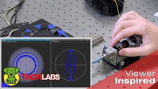
Hi, thank you for this excelent video. I have noticed that in Classical Measurement the elipses angle was 69.2°, while in the Rotating Quarter Wave Plate Measurement it was 58.9°. Is there any explanation for this large difference? From the image, I had the impression that the angle was not exactly 0° in the first measurement of the Rotating QWP approach. But, I am not sure. Could you discuss about it, please?
@dnmessias When using these methods in the lab, the classical (CL) method often returns less accurate results than the rotating quarter-wave plate (R-QWP) approach. While the R-QWP method will usually be more accurate, it does require taking more measurements and making a few more calculations than the CL method. The CL method can be acceptable if only a quick, rough measurement is needed. We have found the variation in results obtained during this demonstration to be typical when making these measurements under the general lab conditions. There are a few reasons these two approaches can provide different polarization values. One is that both methods require accurately measuring the relative transmitted optical power for a complete data set. Reflections from the front and back surfaces of each optic reduce the amount of transmitted power, but this will not affect the provided results as long as the amount of reflected power is constant for the entire measurement set. This is true for the R-QWP method, since the same optics are in the beam for every measurement. However, in the case of the CL measurement, an additional optic is placed in the beam to make the fourth measurement. Because of this, a different amount of power is lost to reflections during the fourth measurement than during the previous three measurements. This difference will affect the accuracy of the calculated polarization values. Another challenge with the CL approach is that only four power measurements are acquired. It can be difficult to accurately measure optical power (especially when the optical power is low), as well to set the polarization optics at the exact angular positions. Small errors in any of these four measurements can have a significant negative effect on the calculated polarization values. In contrast, the effect of an R-QWP measurement error has a smaller effect on the calculated polarization values, since more measurements are made. The multiple measurements help smooth the data, and the number of measurements can be increased to even further increase the accuracy. We summarize these differences after presenting the classical method’s measurements (starting around 8:24).
@djalmir messias We recently learned that we were missing a piece of information when we replied to your original question. We now know (thank you @TsuyoshiTakataniPhd !) that when measuring power values P2 - P8 during the rotating QWP method demonstration, our QWP orientations differed by 5° from the angles we intended. Since we used the intended, and not the actual, angles in our calculations, the polarization ellipse values we calculated for the rotating QWP method were incorrect. They should have been psi = 71°, E_ox = 0.499, and E_oy = 0.867. In addition, the corrected Stokes parameters are: S0 = 1, S1 = -0.502, S2 = 0.385, and S3 = -0.723. We still expect the rotating QWP method to provide more accurate results than the classical method, but the difference should not have been as large as we calculated in the video. Thank you for originally bringing this to our attention!
Hi Thorlabs, A very interesting video, thank you for sharing it with us! Could you please suggest why did you get a quite different Stokes parameters for the two different techniques? did you use different lasers? Or is there any other reason?
@timuralmabetov2213 When using these methods in the lab, the classical method often returns less accurate results than the rotating quarter-wave plate approach. Due to this, we expect some variation between the results. However, you are correct that the results seem to differ by a larger amount than the experimental differences would suggest. The sharp observation skills of another viewer discovered the reason for this. During the second (rotating wave plate) method, we meant to increment the QWP angle 22.5° between each power measurement. However, we accidentally rotated the QWP by 27.5° between the P1 and P2 power measurements. The QWP was then rotated 22.5° before making each of the P2 - P8 measurements, but these power readings were measured at a 5° offset from the intended orientations due to the initial mistake. Due to this, the Stokes parameter numbers we calculated for the rotating wave plate method included some error. When we perform the calculations using the actual angles of the QWP, we obtain the following Stokes parameters: S0 = 1, S1 = -0.502, S2 = 0.385, and S3 = -0.723. The corresponding polarization ellipse values are then: psi = 71°, E_ox = 0.499, and E_oy = 0.867.
@@thorlabs Thannk you very much for your reply! I am glad that you found the cause of the issue. By the way, I have recently used this method instead of classical one and found out that it was really useful and elegant technique. I think it should be noted that during real experimental measurents the laser light usualy not fully polarizerd. There is solution to define polarized part of the emission - find the coefficient P = (S1^2 + S2^2 + S3^2)/S0 then obtain S_polarized = 1/P * S_partially_polarized - (1 - P)/P * S_unpolarized . Then you will get the polarized part of laser light on the Poincare sphere.
@timuralmabetov2213 We are glad you are finding the technique useful, thanks for letting us know! We agree that it is good to keep in mind that light described as “polarized” often includes some unpolarized light, and that the amount of polarized and unpolarized light can be calculated from the Stokes parameters. For those who are interested in the Stokes parameters {S0, S1, S2, S3} for completely polarized, completely unpolarized, and partially polarized light: If the light is completely polarized, then S0^2 = S1^2 + S2^2 + S3^2. If the light is completely unpolarized, then S0^2 > 0 and S1^2 = S2^2 = S3^2 = 0. If the light is partially polarized, so that it includes both polarized and unpolarized light, then S0^2 > S1^2 + S2^2 + S3^2. The degree of polarization (DOP) is the intensity of the polarized light (I_polarized) divided by the intensity of the total light (I_total): DOP = I_polarized / I_total = sqrt(S1^2 + S2^2 + S3^2)/S0. This will be a value between 0 and 1. When the light is partially polarized, the Stokes vector for the polarized portion of the light is {S0_pol, S1_pol, S2_pol, S3_pol} = {sqrt(S1^2 + S2^2 + S3^2), S1, S2, S3} and the Stokes vector for the unpolarized portion of the light is {S0_un, S1_un, S2_un, S3_un} = {S0 - sqrt(S1^2 + S2^2 + S3^2), 0, 0, 0}. When completely polarized light is plotted on a Poincaré sphere, the values appear on the surface of the sphere. When the light is partially polarized, the values are plotted within the sphere’s interior.
Nice video! Please could you explain a solution to this problem? The light I want to measure is not produced from known lasers, they are produced in some physical process(eg. stimulated raman), so their wavelengths are tunable and I don't have a suitable quarter-wave plate for them.
@davidjoy2182 Generally speaking, the basic approach to measuring polarization is always the same and does not depend on the way light is created (e.g. commercially available lasers, stimulated Raman, or another process). However, it can be more challenging to measure the polarization state of broadband sources than that of narrowband lasers like a HeNe, the accuracy of the results can be substantially lower, and your polarimeter should be built using components compatible with the entire wavelength range of interest. One challenge is that the source light needs to be reasonably well collimated, which can be difficult to achieve for larger-sized sources without losing a lot of the optical power. In addition, the polarization measurement will provide a weighted average of the polarization states of all the light components present. This can lead to a complex result and a degree of polarization (DOP) that is significantly in error. If the light source is pulsed, this will increase the complexity and performance requirements of the detection system. If you would like to build your own polarimeter with components compatible with a broadband source, Thorlabs offers superachromatic quarter-wave plates ( www.thorlabs.com/newgrouppage9.cfm?objectgroup_ID=2193 ) and fairly wideband linear polarizers ( www.thorlabs.com/newgrouppage9.cfm?objectgroup_ID=5510 ). Our polarimeters ( www.thorlabs.com/newgrouppage9.cfm?objectgroup_id=1564 ) are designed for broad range of wavelengths. But, just as for a broadband polarimeter you would build yourself, light with bandwidths around 2 nm are needed to obtain high-accuracy results. If this does not answer your question, or if you would like additional information, please contact Tech Support (techsupport@thorlabs.com).
thank you so much for sharing this! i am doing research on metasurface polarization conversion and was figuring out how to characterise the polarization of outcoming light. may i inquire could this method measure only fully polarized light? or inclusing partically polarized light?
The polarimeter described in this setup measures the four Stokes parameters (S0, S1, S2, and S3), which provide information about both the polarized light and the unpolarized light in a light beam. The S1, S2, and S3 parameters describe the polarization state of the polarized light component. Comparing these parameters with S0 provides information about the unpolarized light component. If the square of S0 equals the sum of the squares of S1, S2, and S3 [i.e. S0^2 = S1^2 + S2^2 + S3^2 ], the light is fully polarized. If not, the light is partly polarized or unpolarized. The fraction of polarized light in the beam (the degree of polarization) is a ratio. The numerator is the square root of the sum of the squares of S1, S2, and S3 [i.e. sqrt(S1^2 + S2^2 + S3^2) ]. The denominator is S0. To obtain the degree of polarization as a percent, multiply the numerator by 100 and divide the result by S0 [i.e. 100*sqrt(S1^2 + S2^2 + S3^2) / S0 ]. Note that the polarimeter provides Stokes parameters instead Jones parameters, which are also used to describe polarization state. Jones parameters only provide information about the polarized component of light. Analysis techniques that provide Jones parameters would not be helpful if information about the unpolarized component of the light is needed. Your research sounds interesting! If you'd like to tell us about it, we'd love to hear more.
@@thorlabs Thank you so much for the detail reply! that's really clear! i have read a paper named 'Measuring the Stokes polarization parameters'from group of Edward Collett, they did a lot about characterisation of polarization. they mentioned about the partially poalrized light and fully polarzied light and how to calculated the ratio between them by using stokes parameters. just like you mentioned above. thanks for that! this is quite useful. so my research is about quarter wave plate based on metasurface specifically in mid-infrared region. the strcuture is quite simple but we find it so difficult to characterise the polarized light in infrared region due to its higher frequency than terahertz. luckily, we learn about the method in this video which is quite useful in our case, so we managed to measure stokes parameters by using classic method and it is kind works but still lots of uncertainties in expariment so optimise of results are need and this is what we are working on recently.
@@huanlingzou3313 Thanks for your reply; it's exciting to hear about your metasurface-based quarter-waveplate for the mid-IR! We're very glad we could help and wish you much success in your research 😊
This is a very good video. Please could you explain a solution to this problem? I want to measure a material that emits both right and left-handed circular polarizations but with different proportions (intensities) for one circular polarization excitation(say right-handed). Similarly, the proportions switch upon switching the handedness of the excitation beam. How to measure these two polarizations intensities individually for each handedness excitation?
It may suit your application to use a filter that passes light with one circular polarization handedness and blocks light with the other. A filter of this type can be made using a quarter-wave plate (QWP) followed by a linear polarizer (LP). The QWP will convert both the right- and left-circularly polarized light to linearly polarized light. However, the output linearly polarized light resulting from the incident right-circularly polarized light will have a polarization direction orthogonal to the output linearly polarized light resulting from the incident left-circularly polarized light. The LP can be oriented to block the linearly polarized light corresponding to one circular polarization handedness while transmitting the linearly polarized light component corresponding to the other. While this filter can be used to block circularly polarized light with a specific handedness, incident light that is not circularly polarized can also be transmitted through the filter. In order to determine the intensity of each component of circularly polarized light, first measure the intensity of the light without the LP in place. Then, insert the LP and orient it to block one component of the circularly polarized light. Measure the transmitted intensity, and rotate the LP's transmission axis 90° and measure the intensity again. Comparing these three measurements should make it possible to determine the intensities of the left- and right-circularly polarized components of light. If you have further questions, please feel free to contact Tech Support (techsupport@thorlabs.com , or www.thorlabs.com/locations.cfm).
Thank you very much for sharing this useful technique! I just want to make sure if my finding is right, which is wrong angle positions in the rotating QWP method. The angle of the ring mount is set to 5° when measuring P1(0°) at 11:11, but the angle is 32.5° for P2(22.5°) at 11:29, which is supposed to be 27.5°. The others also have +5° angles. I think all the angles of the mount should be -5° except for P1(0°) because the fast asix has to be aligned. Is that right? Or, is it okay to just set it to 10° when measuring P1(0°)?
@TsuyoshiTakataniPhd You are correct that the P1 and P2 power measurements were separated by 27.5°, instead of the 22.5° increment that we intended. This resulted in all P2 - P8 measurements being measured at a 5° offset from the intended orientations. Thank you very much for letting us know what you saw! While it is not necessary to orient the QWP at particular angles when using the rotating QWP method, it is extremely important to know the QWP angles that are used. When we perform the calculations using the actual angles of the QWP, we obtain the following Stokes parameters: S0 = 1, S1 = -0.502, S2 = 0.385, and S3 = -0.723. The corresponding polarization ellipse values are then: psi = 71°, E_ox = 0.499, and E_oy = 0.867.
I think the 5 degree is there because the plate inside is aligned to the horizontal(visually), not to the zero degree of the rotational mount. It is kinda hard to align that QWP inside the rotaional mount and have the mount's 0 degree positioned perfectly to the horizontal. As long as the increment of angle is correct what the demo showed should still be right.
@toppasan9089 We agree that the polarization axis marks (engravings) on optic housings should not be used to fine-tune alignment. Not only would that be hard to do with precision, the optic is actually assembled at the factory with some tolerance between the optics’ real polarization axis and the mark on the housing, and it is also possible that (unknown to you) a colleague might have previously removed the optic from the housing and replaced it later with its axis significantly mis-aligned with the mark (ask us how we know :) ). Because of this, we always use a precision optical method to determine the orientation of the polarization axis before we use the optic. When Gavin mentioned that he had aligned the fast axis of the QWP to be along the horizontal (7:42), he meant that he had used a method, such as the one described in our video th-cam.com/video/XQwiPm5OtSk/w-d-xo.html , to precisely determine the orientation of the QWP’s fast axis. In the demonstration, as you noted, the angle on the rotation mount’s dial was not 0° when the QWP’s fast axis was precisely aligned horizontal. That is not a problem, as long as that non-zero starting number on the dial is taken into account when reading and adjusting the optic’s angle. Here the goal was to add 22.5° to the number on the dial seven times, which was done... except for one adjustment in which 27.5° was mistakenly added to the number on the dial. The Stokes parameters can still be calculated from the measured values, but the actual orientation angles must be used in the calculations. Using a different rotation mount might have helped us avoid this experimental error. For example, there are mounts that allow you to adjust the position of the “0” on the dial without rotating the mounted optic (such as: www.thorlabs.com/thorproduct.cfm?partnumber=RSP1D ), and there are also Indexing Rotation Mounts that additionally allow the dial to be rotated in discrete increments (such as: www.thorlabs.com/newgrouppage9.cfm?objectgroup_ID=246#3668).
@rashadmabrouk8026 We do not have enough information to know why your ellipse values differ from ours, but one thing to note when calculating the ellipse angle psi, is that the equation we provide (for example, shown at 8:16) assumes the inverse tangent calculation takes the quadrant into account. We used the function named “ATAN2” in MATLAB and Microsoft Excel. If the inverse tangent calculation does not take the quadrant into account, the calculated angle ends up being -20.8°, since the negative S1 value and positive S2 places the angle in quadrant II. In this case, it would be necessary to add 90° to this value to obtain the 69.2° value we calculated. The x-y coordinates of an ellipse with known major and minor dimensions (Max and Min, respectively) and rotation angle psi can be used to plot the ellipse. To calculate these coordinates, we used the following equations and varied the angle theta from 0 to 2pi: x(theta) = Max*cos(theta)*cos(psi) - Min*sin(theta)*sin(psi) y(theta) = Max*cos(theta)*sin(psi) + Min*sin(theta)*cos(psi)
While we have not used a polarimeter to determine the linear diattenuation and birefringence properties of samples, we are aware that an open access paper is available that describes the use of a polarimeter's measurement of Stokes parameters to determine these values. If you would like to read about their approach and evaluate the equations they derived, the paper is: Chen et al., Optics Express 17(18), 15860-15884 (2009).


![[Watch Party] RoV Pro League 2024 Winter | ( Bacon Time Vs FS )](http://i.ytimg.com/vi/lD6z1BugdZw/mqdefault.jpg)


Thanks for listing the RSPC retainer in the components list. That caught my eye and now I am ordering some of them. I usually bolt down three bases (BA1S) to form a clumsy kinematic corner for that very application.
We’re impressed that you created 3-point kinematic position references for yourself using base corner tips! We have seen others orient the edges of two bases at 90° to create a corner reference without realizing that variations along the edges provide a much less precise position reference than 3 contact points. Thanks for letting us know that the RSPC filled a need for you! If you find yourself assembling a unique solution and/or thinking that it would be great if someone made a component that does the same thing - please let us know! There are a lot of 'Customer Inspired' items in the Thorlabs catalog!
For those who find that the fixed RSPC is too limiting, the swiveling RSPCS (www.thorlabs.com/newgrouppage9.cfm?objectgroup_id=47&pn=RSPCS&YVI=16 ) could provide an alternative solution for your application.
Nice video. Thanks. Saved the time, going through the textbooks
Hi, thank you for this excelent video. I have noticed that in Classical Measurement the elipses angle was 69.2°, while in the Rotating Quarter Wave Plate Measurement it was 58.9°. Is there any explanation for this large difference? From the image, I had the impression that the angle was not exactly 0° in the first measurement of the Rotating QWP approach. But, I am not sure. Could you discuss about it, please?
@dnmessias When using these methods in the lab, the classical (CL) method often returns less accurate results than the rotating quarter-wave plate (R-QWP) approach. While the R-QWP method will usually be more accurate, it does require taking more measurements and making a few more calculations than the CL method. The CL method can be acceptable if only a quick, rough measurement is needed. We have found the variation in results obtained during this demonstration to be typical when making these measurements under the general lab conditions.
There are a few reasons these two approaches can provide different polarization values. One is that both methods require accurately measuring the relative transmitted optical power for a complete data set. Reflections from the front and back surfaces of each optic reduce the amount of transmitted power, but this will not affect the provided results as long as the amount of reflected power is constant for the entire measurement set. This is true for the R-QWP method, since the same optics are in the beam for every measurement. However, in the case of the CL measurement, an additional optic is placed in the beam to make the fourth measurement. Because of this, a different amount of power is lost to reflections during the fourth measurement than during the previous three measurements. This difference will affect the accuracy of the calculated polarization values. Another challenge with the CL approach is that only four power measurements are acquired. It can be difficult to accurately measure optical power (especially when the optical power is low), as well to set the polarization optics at the exact angular positions. Small errors in any of these four measurements can have a significant negative effect on the calculated polarization values. In contrast, the effect of an R-QWP measurement error has a smaller effect on the calculated polarization values, since more measurements are made. The multiple measurements help smooth the data, and the number of measurements can be increased to even further increase the accuracy. We summarize these differences after presenting the classical method’s measurements (starting around 8:24).
@@thorlabs Thank you for the response. This kind of tutorial video is very helpfull! Thanks
@djalmir messias We recently learned that we were missing a piece of information when we replied to your original question. We now know (thank you @TsuyoshiTakataniPhd !) that when measuring power values P2 - P8 during the rotating QWP method demonstration, our QWP orientations differed by 5° from the angles we intended. Since we used the intended, and not the actual, angles in our calculations, the polarization ellipse values we calculated for the rotating QWP method were incorrect. They should have been psi = 71°, E_ox = 0.499, and E_oy = 0.867. In addition, the corrected Stokes parameters are: S0 = 1, S1 = -0.502, S2 = 0.385, and S3 = -0.723.
We still expect the rotating QWP method to provide more accurate results than the classical method, but the difference should not have been as large as we calculated in the video. Thank you for originally bringing this to our attention!
Hi Thorlabs,
A very interesting video, thank you for sharing it with us!
Could you please suggest why did you get a quite different Stokes parameters for the two different techniques? did you use different lasers? Or is there any other reason?
@timuralmabetov2213 When using these methods in the lab, the classical method often returns less accurate results than the rotating quarter-wave plate approach. Due to this, we expect some variation between the results. However, you are correct that the results seem to differ by a larger amount than the experimental differences would suggest.
The sharp observation skills of another viewer discovered the reason for this. During the second (rotating wave plate) method, we meant to increment the QWP angle 22.5° between each power measurement. However, we accidentally rotated the QWP by 27.5° between the P1 and P2 power measurements. The QWP was then rotated 22.5° before making each of the P2 - P8 measurements, but these power readings were measured at a 5° offset from the intended orientations due to the initial mistake. Due to this, the Stokes parameter numbers we calculated for the rotating wave plate method included some error. When we perform the calculations using the actual angles of the QWP, we obtain the following Stokes parameters: S0 = 1, S1 = -0.502, S2 = 0.385, and S3 = -0.723. The corresponding polarization ellipse values are then: psi = 71°, E_ox = 0.499, and E_oy = 0.867.
@@thorlabs thank you for your reply!
Glad that you could find the cause of the issue.
@@thorlabs Thannk you very much for your reply! I am glad that you found the cause of the issue.
By the way, I have recently used this method instead of classical one and found out that it was really useful and elegant technique. I think it should be noted that during real experimental measurents the laser light usualy not fully polarizerd. There is solution to define polarized part of the emission - find the coefficient P = (S1^2 + S2^2 + S3^2)/S0 then obtain S_polarized = 1/P * S_partially_polarized - (1 - P)/P * S_unpolarized . Then you will get the polarized part of laser light on the Poincare sphere.
@timuralmabetov2213 We are glad you are finding the technique useful, thanks for letting us know! We agree that it is good to keep in mind that light described as “polarized” often includes some unpolarized light, and that the amount of polarized and unpolarized light can be calculated from the Stokes parameters.
For those who are interested in the Stokes parameters {S0, S1, S2, S3} for completely polarized, completely unpolarized, and partially polarized light:
If the light is completely polarized, then S0^2 = S1^2 + S2^2 + S3^2.
If the light is completely unpolarized, then S0^2 > 0 and S1^2 = S2^2 = S3^2 = 0.
If the light is partially polarized, so that it includes both polarized and unpolarized light, then S0^2 > S1^2 + S2^2 + S3^2.
The degree of polarization (DOP) is the intensity of the polarized light (I_polarized) divided by the intensity of the total light (I_total):
DOP = I_polarized / I_total = sqrt(S1^2 + S2^2 + S3^2)/S0. This will be a value between 0 and 1.
When the light is partially polarized, the Stokes vector for the polarized portion of the light is {S0_pol, S1_pol, S2_pol, S3_pol} = {sqrt(S1^2 + S2^2 + S3^2), S1, S2, S3} and the Stokes vector for the unpolarized portion of the light is {S0_un, S1_un, S2_un, S3_un} = {S0 - sqrt(S1^2 + S2^2 + S3^2), 0, 0, 0}.
When completely polarized light is plotted on a Poincaré sphere, the values appear on the surface of the sphere. When the light is partially polarized, the values are plotted within the sphere’s interior.
wonderful,thank you!
Nice video! Please could you explain a solution to this problem? The light I want to measure is not produced from known lasers, they are produced in some physical process(eg. stimulated raman), so their wavelengths are tunable and I don't have a suitable quarter-wave plate for them.
@davidjoy2182 Generally speaking, the basic approach to measuring polarization is always the same and does not depend on the way light is created (e.g. commercially available lasers, stimulated Raman, or another process). However, it can be more challenging to measure the polarization state of broadband sources than that of narrowband lasers like a HeNe, the accuracy of the results can be substantially lower, and your polarimeter should be built using components compatible with the entire wavelength range of interest.
One challenge is that the source light needs to be reasonably well collimated, which can be difficult to achieve for larger-sized sources without losing a lot of the optical power. In addition, the polarization measurement will provide a weighted average of the polarization states of all the light components present. This can lead to a complex result and a degree of polarization (DOP) that is significantly in error. If the light source is pulsed, this will increase the complexity and performance requirements of the detection system.
If you would like to build your own polarimeter with components compatible with a broadband source, Thorlabs offers superachromatic quarter-wave plates ( www.thorlabs.com/newgrouppage9.cfm?objectgroup_ID=2193 ) and fairly wideband linear polarizers ( www.thorlabs.com/newgrouppage9.cfm?objectgroup_ID=5510 ). Our polarimeters ( www.thorlabs.com/newgrouppage9.cfm?objectgroup_id=1564 ) are designed for broad range of wavelengths. But, just as for a broadband polarimeter you would build yourself, light with bandwidths around 2 nm are needed to obtain high-accuracy results.
If this does not answer your question, or if you would like additional information, please contact Tech Support (techsupport@thorlabs.com).
Thanks for the reply!
thank you so much for sharing this! i am doing research on metasurface polarization conversion and was figuring out how to characterise the polarization of outcoming light. may i inquire could this method measure only fully polarized light? or inclusing partically polarized light?
The polarimeter described in this setup measures the four Stokes parameters (S0, S1, S2, and S3), which provide information about both the polarized light and the unpolarized light in a light beam. The S1, S2, and S3 parameters describe the polarization state of the polarized light component. Comparing these parameters with S0 provides information about the unpolarized light component. If the square of S0 equals the sum of the squares of S1, S2, and S3 [i.e. S0^2 = S1^2 + S2^2 + S3^2 ], the light is fully polarized. If not, the light is partly polarized or unpolarized. The fraction of polarized light in the beam (the degree of polarization) is a ratio. The numerator is the square root of the sum of the squares of S1, S2, and S3 [i.e. sqrt(S1^2 + S2^2 + S3^2) ]. The denominator is S0. To obtain the degree of polarization as a percent, multiply the numerator by 100 and divide the result by S0 [i.e. 100*sqrt(S1^2 + S2^2 + S3^2) / S0 ].
Note that the polarimeter provides Stokes parameters instead Jones parameters, which are also used to describe polarization state. Jones parameters only provide information about the polarized component of light. Analysis techniques that provide Jones parameters would not be helpful if information about the unpolarized component of the light is needed.
Your research sounds interesting! If you'd like to tell us about it, we'd love to hear more.
@@thorlabs Thank you so much for the detail reply! that's really clear! i have read a paper named 'Measuring the Stokes polarization parameters'from group of Edward Collett, they did a lot about characterisation of polarization. they mentioned about the partially poalrized light and fully polarzied light and how to calculated the ratio between them by using stokes parameters. just like you mentioned above. thanks for that! this is quite useful. so my research is about quarter wave plate based on metasurface specifically in mid-infrared region. the strcuture is quite simple but we find it so difficult to characterise the polarized light in infrared region due to its higher frequency than terahertz. luckily, we learn about the method in this video which is quite useful in our case, so we managed to measure stokes parameters by using classic method and it is kind works but still lots of uncertainties in expariment so optimise of results are need and this is what we are working on recently.
@@huanlingzou3313 Thanks for your reply; it's exciting to hear about your metasurface-based quarter-waveplate for the mid-IR! We're very glad we could help and wish you much success in your research 😊
This is a very good video. Please could you explain a solution to this problem? I want to measure a material that emits both right and left-handed circular polarizations but with different proportions (intensities) for one circular polarization excitation(say right-handed). Similarly, the proportions switch upon switching the handedness of the excitation beam. How to measure these two polarizations intensities individually for each handedness excitation?
It may suit your application to use a filter that passes light with one circular polarization handedness and blocks light with the other. A filter of this type can be made using a quarter-wave plate (QWP) followed by a linear polarizer (LP). The QWP will convert both the right- and left-circularly polarized light to linearly polarized light. However, the output linearly polarized light resulting from the incident right-circularly polarized light will have a polarization direction orthogonal to the output linearly polarized light resulting from the incident left-circularly polarized light. The LP can be oriented to block the linearly polarized light corresponding to one circular polarization handedness while transmitting the linearly polarized light component corresponding to the other.
While this filter can be used to block circularly polarized light with a specific handedness, incident light that is not circularly polarized can also be transmitted through the filter. In order to determine the intensity of each component of circularly polarized light, first measure the intensity of the light without the LP in place. Then, insert the LP and orient it to block one component of the circularly polarized light. Measure the transmitted intensity, and rotate the LP's transmission axis 90° and measure the intensity again. Comparing these three measurements should make it possible to determine the intensities of the left- and right-circularly polarized components of light. If you have further questions, please feel free to contact Tech Support (techsupport@thorlabs.com , or www.thorlabs.com/locations.cfm).
Thank you very much for sharing this useful technique! I just want to make sure if my finding is right, which is wrong angle positions in the rotating QWP method. The angle of the ring mount is set to 5° when measuring P1(0°) at 11:11, but the angle is 32.5° for P2(22.5°) at 11:29, which is supposed to be 27.5°. The others also have +5° angles. I think all the angles of the mount should be -5° except for P1(0°) because the fast asix has to be aligned. Is that right? Or, is it okay to just set it to 10° when measuring P1(0°)?
@TsuyoshiTakataniPhd You are correct that the P1 and P2 power measurements were separated by 27.5°, instead of the 22.5° increment that we intended. This resulted in all P2 - P8 measurements being measured at a 5° offset from the intended orientations. Thank you very much for letting us know what you saw!
While it is not necessary to orient the QWP at particular angles when using the rotating QWP method, it is extremely important to know the QWP angles that are used. When we perform the calculations using the actual angles of the QWP, we obtain the following Stokes parameters: S0 = 1, S1 = -0.502, S2 = 0.385, and S3 = -0.723. The corresponding polarization ellipse values are then: psi = 71°, E_ox = 0.499, and E_oy = 0.867.
I think the 5 degree is there because the plate inside is aligned to the horizontal(visually), not to the zero degree of the rotational mount. It is kinda hard to align that QWP inside the rotaional mount and have the mount's 0 degree positioned perfectly to the horizontal. As long as the increment of angle is correct what the demo showed should still be right.
@toppasan9089 We agree that the polarization axis marks (engravings) on optic housings should not be used to fine-tune alignment. Not only would that be hard to do with precision, the optic is actually assembled at the factory with some tolerance between the optics’ real polarization axis and the mark on the housing, and it is also possible that (unknown to you) a colleague might have previously removed the optic from the housing and replaced it later with its axis significantly mis-aligned with the mark (ask us how we know :) ). Because of this, we always use a precision optical method to determine the orientation of the polarization axis before we use the optic. When Gavin mentioned that he had aligned the fast axis of the QWP to be along the horizontal (7:42), he meant that he had used a method, such as the one described in our video th-cam.com/video/XQwiPm5OtSk/w-d-xo.html , to precisely determine the orientation of the QWP’s fast axis.
In the demonstration, as you noted, the angle on the rotation mount’s dial was not 0° when the QWP’s fast axis was precisely aligned horizontal. That is not a problem, as long as that non-zero starting number on the dial is taken into account when reading and adjusting the optic’s angle. Here the goal was to add 22.5° to the number on the dial seven times, which was done... except for one adjustment in which 27.5° was mistakenly added to the number on the dial. The Stokes parameters can still be calculated from the measured values, but the actual orientation angles must be used in the calculations.
Using a different rotation mount might have helped us avoid this experimental error. For example, there are mounts that allow you to adjust the position of the “0” on the dial without rotating the mounted optic (such as: www.thorlabs.com/thorproduct.cfm?partnumber=RSP1D ), and there are also Indexing Rotation Mounts that additionally allow the dial to be rotated in discrete increments (such as: www.thorlabs.com/newgrouppage9.cfm?objectgroup_ID=246#3668).
how did calculate the ellipse parameters because i got different values and how did you plot it
@rashadmabrouk8026 We do not have enough information to know why your ellipse values differ from ours, but one thing to note when calculating the ellipse angle psi, is that the equation we provide (for example, shown at 8:16) assumes the inverse tangent calculation takes the quadrant into account. We used the function named “ATAN2” in MATLAB and Microsoft Excel. If the inverse tangent calculation does not take the quadrant into account, the calculated angle ends up being -20.8°, since the negative S1 value and positive S2 places the angle in quadrant II. In this case, it would be necessary to add 90° to this value to obtain the 69.2° value we calculated.
The x-y coordinates of an ellipse with known major and minor dimensions (Max and Min, respectively) and rotation angle psi can be used to plot the ellipse. To calculate these coordinates, we used the following equations and varied the angle theta from 0 to 2pi:
x(theta) = Max*cos(theta)*cos(psi) - Min*sin(theta)*sin(psi)
y(theta) = Max*cos(theta)*sin(psi) + Min*sin(theta)*cos(psi)
Is there any formula to determine linear diattenuation and bi refringes
While we have not used a polarimeter to determine the linear diattenuation and birefringence properties of samples, we are aware that an open access paper is available that describes the use of a polarimeter's measurement of Stokes parameters to determine these values. If you would like to read about their approach and evaluate the equations they derived, the paper is: Chen et al., Optics Express 17(18), 15860-15884 (2009).