How to design PCB in Proteus in 10 Minutes || +5v Power Supply Circuit Design and Simulation

แชร์
ฝัง
  • เผยแพร่เมื่อ 11 มิ.ย. 2020
  • #ElectroTechCC #PCBdesign #CircuitDesign
    A voltage regulator is one of the most widely used electronic circuitry in any device. A regulated voltage (without fluctuations & noise levels) is very important for the smooth functioning of many digital electronic devices. A common case is with micro controllers, where a smooth regulated input voltage must be supplied for the micro controller to function smoothly.
    You may also like this article on Regulated Power Supply
    Voltage regulators are of different types. In this article, our interest is only with IC based voltage regulator. An example of IC based voltage regulator available in market is the popular 7805 IC which regulates the output voltage at 5 volts. Now lets come to the basic definition of an IC voltage regulator. It is an integrated circuit whose basic purpose is to regulate the unregulated input voltage (definitely over a predefined range) and provide with a constant, regulated output voltage.
    An IC based voltage regulator can be classified in different ways. A common type of classification is 3 terminal voltage regulator and 5 or multi terminal voltage regulator. Another popular way of classifying IC voltage regulators is by identifying them as linear voltage regulator & switching voltage regulator. There is a third set of classification as 1) Fixed voltage regulators (positive & negative) 2) Adjustable voltage regulators (positive & negative) and finally 3) Switching regulators. In the third classification, fixed & adjustable regulators are basically versions of linear voltage regulators.
    Fixed Voltage Regulators
    These regulators provide a constant output voltage. A popular example is the 7805 IC which provides a constant 5 volts output. A fixed voltage regulator can be a positive voltage regulator or a negative voltage regulator. A positive voltage regulator provides with constant positive output voltage. All those IC’s in the 78XX series are fixed positive voltage regulators. In the IC nomenclature - 78XX ; the part XX denotes the regulated output voltage the IC is designed for. Examples:- 7805, 7806, 7809 etc.
    A negative fixed voltage regulator is same as the positive fixed voltage regulator in design, construction & operation. The only difference is in the polarity of output voltages. These IC’s are designed to provide a negative output voltage. Example:- 7905, 7906 and all those IC’s in the 79XX series.
    Adjustable Voltage Regulator
    An adjustable voltage regulator is a kind of regulator whose regulated output voltage can be varied over a range. There are two variations of the same; known as positive adjustable voltage regulator and negative adjustable regulator. LM317 is a classic example of positive adjustable voltage regulator, whose output voltage can be varied over a range of 1.2 volts to 57 volts. LM337 is an example of negative adjustable voltage regulator. LM337 is actually a complement of LM317 which are similar in operation & design; with the only difference being polarity of regulated output voltage.
    Disclaimer -
    Video is for educational purpose only. Copyright Disclaimer Under Section 107 of the Copyright Act 1976, allowance is made for "fair use" for purposes such as criticism, comment, news reporting, teaching, scholarship, and research. Fair use is a use permitted by copyright statute that might otherwise be infringing. Non-profit, educational or personal use tips the balance in favor of fair use.

ความคิดเห็น • 21

  • @VijayParmar
    @VijayParmar 3 ปีที่แล้ว

    👌👌👌👌

  • @KK3DTechnology
    @KK3DTechnology 3 ปีที่แล้ว +1

    👍🏻

  • @piyushanchalia7463
    @piyushanchalia7463 3 ปีที่แล้ว +1

    Dude can u please let me know what u added at the last replacing tge ac supply

  • @maeannpojas9141
    @maeannpojas9141 11 หลายเดือนก่อน

    Good day sir, I can't find the "netlist transfer to ARES", how to find it?

  • @aqilahhusna8619
    @aqilahhusna8619 ปีที่แล้ว +1

    ZL10000?

  • @jolssumaylo
    @jolssumaylo 2 ปีที่แล้ว

    Also in schematic there's an error in J1 and J2. It says that no model is specified. Please help. THANKYOUII

    • @ElectroTechCC
      @ElectroTechCC  2 ปีที่แล้ว

      You can use screw connector for J1 and J2

  • @karandahiwale8770
    @karandahiwale8770 2 ปีที่แล้ว +1

    This circuit is for 230v ac to 5v dc if i m correct??

  • @jolssumaylo
    @jolssumaylo 2 ปีที่แล้ว

    Hello I can't place the lead at PBC. It says that D1 is not packaged what is the meaning of that. Please help me

    • @ElectroTechCC
      @ElectroTechCC  2 ปีที่แล้ว

      You have to click on ok in that pop up Window. After that you have to search "LED" in the search bar. And you will get LED foot print

    • @user-cx5ep7xl3b
      @user-cx5ep7xl3b 2 ปีที่แล้ว

      th-cam.com/video/l2QpPURl3W8/w-d-xo.html

  • @keviinnhr_
    @keviinnhr_ ปีที่แล้ว +1

    how much output trafo if output pcb layout 5v dc ??

  • @atharvayadav9859
    @atharvayadav9859 หลายเดือนก่อน

    Can you plz Mention all the components

    • @ElectroTechCC
      @ElectroTechCC  18 วันที่ผ่านมา

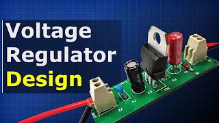
      1 step down transformer 230V to 5V
      4 Diode 1N4007 for rectifier
      1 Electrolytic Capacitor 100uF/16V
      1 Voltage Regulator LM7805
      1 Ceramic Capacitor 104
      1 Current Limiting Resistor 1Kohm
      1 Indicator LED

  • @lokamsoeung8692
    @lokamsoeung8692 2 ปีที่แล้ว

    May I know the current(Amp)?

    • @ElectroTechCC
      @ElectroTechCC  2 ปีที่แล้ว +1

      Less than 1 Amp

    • @keviinnhr_
      @keviinnhr_ ปีที่แล้ว

      how much output the current (V)??