Unipolar to Bipolar: 28BYJ-48 Stepper Motor Upgrade with explanation

ฝัง
- เผยแพร่เมื่อ 7 ก.พ. 2025
- This is the long-winded method to turn your Unipolar 28BYJ-48 stepper motors from unipolar to bipolar - by cutting out the center coil.
I'll post a shorter, to-the-point video later, but the idea here is to cover the why, not just the how.
The Datasheet for these motors is here:
download.mikro...
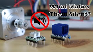
This is a precursor to using a cheap pancake motor to control your 3D printer - or other precision device - with improved and even silent stepping depending on your driver.
Thanks!
Support the project!
/ printshift
Check out our website!
printshift3d.com
Project GitHub - PrintShift is open source! Build along and make your Mini a proper factory!
github.com/pae...


This is a great video! Love it when the explination is not just the how but the why.
This is a great video. Thank you sir! I wish there was a bipolar version of this motor so I wouldnt have to do this myself..
There are a lot of pancake steppers now, but the price isn't very similar. Give it a couple of years maybe
Thank you very much man
I am wondering why It's made unipolar if Bipolar is better in terms of Control and Resolution??
To drive a Unipolar, you just need a Darlington transistor array (well, 4 of them) and a counter to power each half-coil in order, since the center of the coils are always grounded. Super simple. To drive a bipolar, you need to swap the power and ground for each coil - so, a stepper driver or a set of H bridge motor drivers. So... if you don't need the resolution, you can get away with much cheaper electronics.
@@PaulChase now Makes sense thanks you 👍👍
Excelent!
That was great thank you.
if not cut trace ... what happen?
Hi. Can you suggest a stepper motor which have a low step angle( i need high res for measurements) also small such that it can be used near an electromagnet.
Cool video but really as a beginner I have no clue what you are talking about.
Please explain what exactly happens now with this motor. How is better and for what purpose? And if I cannot use my controller anymore then how can I control it now?
I'm looking for my motor to be able to go forward and backward, and I am making that project now. Can this video help me?
Thanks.
Making it bidirectional really increases the torque and lets you control it smoothly with microstepping. It can go forwards and backwards before being modified, though.
Ok so I got a A4988 and am willing to try. Am just a bit confused of wiring and code..
Hi, should we swap the cables addtionally? yellow and pink?
Mr. Paul I think your explanation is very cool, congratulations. Could you explain to me how to use this 28BYJ-48 motor with the A4988 Drive using arduino?
Mine came with a Darlington transistor driver - so to drive, you can just turn on each coil in sequence, and it will click over. AFTER making it bipolar, you need a fancier h-bridge driver - cuz each coil needs to be powered and grounded in sequence.
Can we replace this Mod virsion in place of Nima17 ?
Nema 17 is WAY bigger and stronger. A nema 11, I'd say yes, nema 14... maybe? These are way geared down, so slow but high torque. However, the gears are plastic and will strip if overloaded.
@@PaulChase yes , I know Nima17 is bigger and better but I asked just to know that what if cnc made with nima17 2.5kgcm SM replaced with Modified Bipol 28-BYJ ? Will it work similarly in terms of Accuracy or Its Backlash will cause problem ( if run without Load ) , also will it Support Microstepping of N17 ?
@@PaulChase : The final gear is attached to the output shaft by a cup-washer, acting as a friction clutch. This should stop the gears from stripping... the problem then would be that your mechanism has lost it's accuracy, in much the same way as if the stepper had missed steps.
It would depend what you are using it for. If your machine requires precise movement / repeatability, these are not really suitable. The gears introduce backlash that you do not get with a direct drive stepper without a gearbox. There is also a friction clutch on the output shaft which could easily slip. This would stop your mechanism from accurately returning to the same position repeatedly.
If accuracy / repeatability is not important, say in something like an animitronic toy or sculpture, these modified motors could be ideal.
Does the torque change with this? Also, with gear reduction, would these work on the larger belts?
Bipolar is more torque - twice the torque with simple math, because the coils are twice the size. The downside is a more complicated driver, but, well, drivers are cheaper now. With enough gear reduction anything is possible, but it's more efficient to have a good motor coil - any sort of gearing will reduce speed, and that'll impact Z-movement on printers.
How hard would it be to change the code of a program to make it useable for bipolar?
You need to change hardware to go bipolar. Normally these motors are controlled by turning on 4 transistors in series, one per coil, circuit is transistor->coil->ground. Bipolar, the coils run both ways - so you need an h-bridge per coil (two per motor) which is basically 8 transistors. Generally you use purpose built stepper drivers, which do fancier switching and more efficiency
0:45 - a Darlington transistor is just a high power transistor. ???
They're wired as one, but on the silicon it's two transistors with their collectors chained together, for higher current gain. You can build your own with any two npn transistors, but they're useful enough that the ICs are cheap and readily available
It just sounded like you were saying Darlington pairs are high power or control high power. Certainly there are many lower current Darlington pairs. Their configuration is for high current gain, that is what Mr. Darlington achieved.@@PaulChase
Thank for giving this problem. By the way, I want to know steps/re (out shaft of motor) in this case (unpio is 64*64 step/re) give me this number. Tks.
The manufacturer says 2048 full steps per revolution, which is full-steps assuming it's got an integrated 1:64 gearbox. The motor comes in different variants with different gearboxes internally, though, so best to check. Also, your steps per mm will be higher if you use a modern stepper driver that implements microstepping
@@PaulChase Tks! Yesterday I test on arduino uno and It is 2048 step/revolution. It's right as you said. Tks .
Parametters of configuration need caculation and experience. Give me these para...
Considering these are about a buck a piece, and a4988's are about a buck a piece, yeah I think I'll take the time to mod a bulk pack of these.
What driver do you recommend for these bipolar motors?
Any bipolar driver that can handle the current these motors take (which is not a lot) should be fine. A4988 are very popular for this purpose.
I've run these even with the fancier Trinamic drivers - 2209 and 2130 - but with the built-in gear reduction on the motor there's really no need for higher microstepping, but they can still do endstopless homing, which is nice.
@@PaulChase : Hi Paul, I enjoyed your video, thanks... great little motors for learning with.
By 'endstopless homing', do you mean driving the mechanism against the end of it's travel to identify a known position?
Cut the tracer on the red... done.
Does it run??? Why now show it running?
Yep, it does run! Four of them are powering this printer: th-cam.com/video/3TYawz8agKE/w-d-xo.html
do you need to double the voltage to use it like this?
Nope - it will draw more amps per turn, but it's such a small motor that nearly any stepper driver can handle it.
@@PaulChase V = I * R. If you keep V the same, and double R (because you now have two coils in series) the current halves, not doubles. Or I'm not really understanding it.
There is no need to modify the motor at all! Just ignore the middle red wire and use a bipolar controller and the two coil ends and it works exactly the same!!
Well exactly the same as the described modification, but it is not the same, because now you are using double the length of wire, and so double the resistance and half the current. You can make up for it by doubling the voltage to 12v.
If you are going to modify it, what you really want to do is double up the wires so you have half the windings like before, but twice the copper and thus have the same resistance and hence current. You can do that by taking the two coil wires in the middle terminal (the mid point of the coil) and connect one to the end, and the other to the start. If you don't do that, cut the middle trace to one coil and add another "red" wire into the "middle" of the other coil, and now you can use only half the windings and run it bipolar and have the same performance as unipolar. I have also noticed the coils only fill up half the motor, so you could just rip out the coils and put in a single winding of a thicker wire.
I'm converting one to a servo and need the shorter motor this has. The "short" servos are like $50 to buy.
Look at the circuit diagram - unmodified, every coil is connected to the ground in the middle - you can drive it from the ends to the ground, but without cutting that connection you'll be running at 1/4 power. You also can't do microstepping cuz the current would be flowing from one coil through the ground leg to the other coil