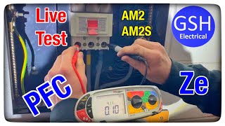
Ze and PFC Electrical Tests on a 3 Phase Board | PTT

ฝัง
- เผยแพร่เมื่อ 21 พ.ย. 2019
- Watch our quick tutorial presented by our skilled trainer, Sam Craig, on how to carry out External Loop Impedance (Ze) and Prospective Fault Current (PFC) tests on a three phase distribution board.
Ze is a measurement of the external earth fault impedance of the installation. It is the measured resistance of the supply transformer winding, the supply phase conductor, and the earth return path of the supply.
A PFC test, or Prospective Fault Current test detertmines the current that will flow in the event of a line to earth fault and line to neutral fault.
Every distribution board must be tested to make sure that the fault current does not exceed that specified for the protective devices concerned. At Proactive Technical Training, we are here to ensure your safety when it comes to inspection and testing electrical installations.
For more information on the technical training services we provide, head to our website:
www.proactivetechnicaltrainin...
If you are interested in City & Guilds courses, check out the training we provide:
www.proactivetechnicaltrainin...


![[4K] TREASURE(트레저) “KING KONG” Band LIVE Concert 킹콩은 라이브를 찢어🦍 [it’s KPOP LIVE 잇츠라이브]](http://i.ytimg.com/vi/p8bLLOxPDD8/mqdefault.jpg)


Yes, that is correct. The Ze is the impedance at the board, but only if DB is at origin. The boards in the training establishment will include the internal wiring in the building, so are in fact a Zdb.
An estimate of Pfc between two phases, is the highest current measured between phases and neutral and multiplied by 1.732 or root 3. To estimate the current if all three phases and neutral came together would be double the current between phase and neutral.
Hope that helps, and do get in touch if you need further?
Thanks for the question and happy testing.
One of the best videos in TH-cam, which I found with knowledgeable, and explanations why we do this testing . Thanks to upload and share your knowledge with others.
The book suggests testing Phase to neutral(single-phase) and doubling the result to obtain a 3-phase value. Since making the video, I have started also measuring the Phase to earth which as you say, could be a higher reading as it is likely to include parallel paths. In other words, you are proceeding exactly as you would with a single-phase installation but doing 3 tests; one for each phase. This is useful if you have a single-phase board fed from the three-phase board. If this is the case, you would have all the info needed for PFC on the single-phase board, and for the three-phase PFC, you simply double the highest result.
Let me know if you need further.
Thank You
your video make me confident to do Ze/PFC testing .
Thank you for this Video
My question is if this test is Carried out for main low voltage panel with 2500 A breaker , so the main breaker should be off ? Right ?? And we will measure for the incoming point of the breaker which is live ?
We did this as a safety procedure or just to take the exact reading for pfc and ze ?
A exellent video sir.well done.
I watched all your videos
Hi very good explanation. Keep it up
Thank you!
Very handy!
Nice video from Tresham Colle
Out of interest what was the size of the breakers to compare the pfc calculations against? Otherwise a faultless video.
Hi thanks for the Video. Can you tell me please why you had the Main Breaker turned off when doing your PSCC test? surely the main switch and breakers should be on ?
He tested it at the other pole of the breaker that's live. The installation beyond the main breaker is dead, before the main breaker its still live
@@MK-wf1eg I know that but to make sure you are getting all the Parallel paths the main switch and breakers should all be on.
Hi, The main switch is should in the "OFF position when carrying out a test of PFC because the we are looking for the worse case scenario: when the resistance is at it's lowest and the current will be at the highest. If the switch was on, you could theoretically get voltage drop which would change the reading. When the switch is off, you are still including parallel paths as long as the earthing conductor and all the extraneous-conductive-parts are connected to the MET via the equipotential bonding.
Hope that helps..
@@daytonamann5618 So for the current to be at its highest you would need the main switch on! With the main switch off their is no current.
@@gregsmith5553 No; The bottom of the switch is live at all times, so the current is measured at that point. The installation is isolated and so there is no voltage in the actual system when the switch is off!
Great video, thanks for your time. A hypothetical question, what would be the process for the Ze at a sub board fed from the 3 phase DB?
The process for measuring loop impedance at the sub board would be the same but in this case you are measuring Zs at the DB not Ze and therefore the earth/cpc remains connected for this test.
Thanks for your reply, so essentially a loop test at the sub board, croc clip on to MET and probe incoming L&N. This then giving you the Ze + R1+R2 of the cable going to the sub board.
@@kylepeace3252 Correct.
Should show switching on meter
Good Vid thank you. Am I right in saying that at this distribution board the Ze is actually the Zdb and when advising about the current generally the x 1.73 is the fault for 2 phases and the x 2 is for short between all three phases ? please advise.
So iit would be the same if you use a ROBIN kts 1620 MFT?
Is that a Fluke MFT? If it is then you would make the L-N/ L-PE using the buttons on the side of the display.
How do you get zs at db for 3 -phase board?
Earthloop is zs at db on test sheet but is ze on page 2
Could someone please put me right, I thought that the test carried out was not the the PFC as he only tested phase to neutral and not phase to earth which may have given a higher fault current which then would have been the PFC, it showed on the meter that only 2 probes was in use which was the line and neutral test probes, I do stand to be corrected.
The book suggests testing Phase to neutral(single-phase) and doubling the result to obtain a 3-phase value. Since making the video, I have started also measuring the Phase to earth which as you say, could be a higher reading as it is likely to include parallel paths. In other words, you are proceeding exactly as you would with a single-phase installation but doing 3 tests; one for each phase. This is useful if you have a single-phase board fed from the three-phase board. If this is the case, you would have all the info needed for PFC on the single-phase board, and for the three-phase PFC, you simply double the highest result.
Let me know if you need further.
What is the name of that instrument you used
it is a Martindale ET 4000
im confused you done a three lead test for the pfc does that mean you included pefc and pscc? and that made your pfc?
With the meter shown in the video it requires two tests using three leads. One to select and measure PEFC and then one to select and measure PSCC. The three leads remain in the same position for each test the meter then measures between L-E for PEFC and then L-N for PSCC. The higher of the two readings (for a single phase supply) is taken as the PFC. In the case of three phase measurements there is no need to measure the PEFC. We are only are interested in the PSCC L-L so we measure L-N and take this reading and double it to be recorded as the PFC.
@@proactivetechnicaltraining4431 hi buddy. After Ze is measured between the three phases and earth, do we have to double the highest Ze value to record on our test sheet? Or is it only the pfc we double?
@@kristianhumphreys7984 Hi Kristian, We just take three Ze measurements and take the highest. The PFC is measured between L1, L2 and L3 to Neutral, take the highest and double it. Note: we only measure PSCC on 3-phase as that is at 400v. The PEFC is only 230v so we don't need to measure it. Let me know if you need further?
Maybe the ze would of been within .35 if you had nulled your leads 🤦🏻♂️🤣
DONT AGREE. Measuring phase to neutral shortcircuit is not going to give you three phase PFC even if you multiply by 1.73 or 2. You better have a look at schneider cahier technique 158 and compare the formulas for all shortcircuit types. you will see that you need to measure between two phases and multiply x1.16. Many mft meters support measuring between phases even if you select L-N test. For example fluke 1654B. The only place you could do that aprox x2 times (no x1,73) is subject to the neutral being the same size and length as the live, all the way upstream and if you are far away fron the transformer so the transformer windong impedance is much smaller than the cable. Things that you will never be 100% sure. Hope this comment helps you.
And if you dont believe what i said and dont know how to check, think about it. If it was so easy as doubling it up you would get that info from the meter when you are doing LN tests.
YOU SHOULD BE BANNED.
TEACHING BARE HANDS within inches of 3 phase terminals AND EXPOSING 'CROSS CHEST SHOCK HAZARD.
YOU NEED TO BE REMOVED FROM TEACHING ANYONE.