Phase Sequence Detector (Full Lecture)

ฝัง
- เผยแพร่เมื่อ 16 พ.ค. 2019
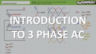
- In this lesson we'll discuss phase sequence and examine the practical application and theory of operation of a phase sequence detector circuit for 3 phase AC systems. (Full Lecture)
• EET112 Unit 1 Workshee...


Nice to see an empirical demonstration of this. Intuitively it makes sense that the phase shift in current through the capacitor would mostly follow the downstream pathway with the most favourable voltage drop, even if impedance is the same both ways.
thanks for your effort sir
Thanks for lecture, help me understand
Who is interested,I calculated the case when capacitor is connected to B and if the sequence ABC is needed then lamp A indeed lights dimly and lamp C is brighter.
Hello Jim, Any idea if we connect capacitor to the central L2 phase and the lamps to L1 and L3.Will the dim lamp indicate the sequence then?Hence the the lamp what is dim shows the leading phase and the bright lamp shows the lagging phase. If The lamp connected to L1 is dim,then the phase sequence is L1,L2,L3.
I made a mistake during this video that might be an interesting discussion point. I thought I could use Kirkhoff's voltage law to check my work, specifically the results in 'sum' green column shown on the video at 16:39. If we consider one loop, say the L2 to L3 loop, then I though I could simply add the voltage drop phasor for each element and come up with the phasor subtraction of L2-L3. I reasoned that I could ignore the L1 arm because it was already taken into account by the summation. Wrong! L1 also joins the loop on the input side, it is not so easy.
True dat. For unbalanced 3 wire Y configurations there will be a voltage differential between the two disconnected central nodes. KVL should yield the same result for all 3 loops (difference of load central node with respect to source central node = L1-V1=L2-V2=L3-V3). The advantage of 4 wire Y configurations is that the neutral wire keeps both central nodes at the same potential.
@@bigbadtech Oh, of course (forehead slapping moment)! Thanks, it was actually easier than I thought, and very simple to understand.