Thanks; I did this over a year ago when needing to test a salvaged stepper motor (from a damaged printer), but then, afterward, put the motor in a box and dismantled the set up; so I completely forgot how to do this. Just got the motor out for a project and only then remembered there was this process; I had saved this video in a playlist thank goodness.
The sense resistors on the driver board in the video are 0.100Ω (R100). Should that not be used instead of 0.068Ω ? I understand that the sense resistor values used vary depending on the manufacturer but I want to make sure I am not missing something.
Yes, you are correct. You should use the actual resistance value of your current sensing resistors. I've used 0.068Ω as an example in this video because this seems to be the most commonly used current sensing resistor.
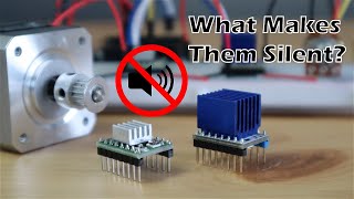
a note for anyone watching, the heatsink must be placed on the UNDERSIDE of the PCB. The datasheet shows there are 4 thermal vias (small holes in the pcb) leadigng to the bottom of the board where the headsink can be attached. The chips's top is very thermally-insulating and so a heatsink on top will do practically nothing. Annoyingly the pins on the breakouts are not long enough after attaching the headsink to the ender side for breadboards or female connectors. Youll have to solder it to a stripboard instead (or replace the pins/flip round etc). Airflow is a bigger factor for cooling these chips, make sure to use a radial fan over an axial fan and the airflow should be perpendicular to the board &/or headsink.
It would have been nice to include a confirmation using the voltmeter and a stepper coil. It seems that one advantage of the approach measuring the current through a stepper coil and measuring current through the multimeter would be that you may not need to do any calculations since you'd be able to read the current directly. However, you would need to be careful to start with the pot at minimum current and then increase from that point. Another advantage is that you;d have no doubt that your setting was correct.
The Vref is set to 0.48v, but one out of 6 or 7 times the motor spins in opposite direction ! I have my DIR set to to clockwise, and it works fine, until suddenly the motor DIR spins **anticlockwise** !, and them goes back to it's programmed DIR ( i.e clockwise ) I have a Nema 17 and have used the formula as per data sheet and your video.
Hi! Thanks for the video! I'm driving my stepper driver from a Piu Pico that has a 3,3V output. Does that have any effect on the Voltage I need to set?
You should place the GND right at the chip not on the arduino, you want to measure what the chip sees as pwr and gnd. Granted there may not be enough current to produce a voltage drop but its always BEST practice to GND at the device you are measuring same goes with power. You probably want to ensure STEP is pulled low.
When you say "the maximum motor current", does that mean per phase or for both phases combined? The datasheet for my stepper just says "1A max per phase" and it has two phases, so does that mean the maximum motor current is 2A or should I stick to 1A?
It's a free on that came with a heatsink. There is nothing special about it, it just needs to be small enought to not catch on the surrounding components.
@@MichaelKlements I found a really old and worned out screwdriver and it was the perfect size, but when I try to measure the Vref it just reads the logic input voltage, no matter how much I turn the potentiometer. I was using a PI Pico at first, then I tried using the pico, but with a separate 5v power suply, instead of the built in 3.3 volts, and still just reads the input logic voltage, I quintuple checked and I am probing the right conections, and I bought 4 of them for a project, and all 4 of them do the same thing.
Thanks for tutorial. I did exactly what you explained, but there is strange noise from stepper motor after every single motion. Imax is 1A, Rs equals to 0.2, therefore Vref is 1.6 minus 10% for safety. I would appreciate your help.
No matter what I do, the voltage on the motor driver never changes when I rotate the screw. Two A4988s and one tc2209 and it's the same behavior with all of them. Any idea what I could be doing wrong?
I have a question. I am using 24 volts to power the Nema 17 bipolar motor. Is the process for setting the Vref the same? All I have to connect si the logic pwoer supply and then connect reset and sleep and then adjust the potentiometer to adjust the vref?
Sir, Great video. Learned a lot. I have purchased a stepper motor from the local market. It has following details: TYPE 17PM-K310-33VS NO. T4524-01 MINEBEA-MATSUSHITA MOTOR CORPORATION. There are no other details. I cannot find a datasheet. I am using CNC shield 3 & A4988 driver. What voltage should I set? Thanks
Hi, I don't quite understand the whole end result of using stepper motor driver module to limit current. Lower voltage will lower motor speed (and torque). Will using driver module to limit current allow for faster rpm while limiting torque?
What you seem to be describing applies to brushed dc motors. Stepper motors operate entirely differently and require a driver to energise the coils sequentially a to move them. Motor speed is dependent on the frequency of pulses and torque is dependant on current.
@@MichaelKlements thanks for the reply Michael, a brushed motor is what I am looking to limit current to. Specifically small dc motors such as a 130, or 180 dc motor. My application would need to limit current when a geared mechanism reaches the end of it's travel and causes the motor to stall. Stall amperage for these motors is just under or just over 1 amp. I can accomplish my gosh simply by running the motors well below rated voltage, but would prefer to run at rated voltage and current. Would these driver modules work to limit current to a dc motor?
You'd probably have to build your own dc motor driver (or modify an existing one) to do what you're wanting to as it is a somewhat unusual requirement. You can't use these drivers (as far as I'm aware) to drive brushed DC motors.
What do I do when I don't know the maximum motor current? I salveged a motor from an old scanner and it only sais it has 5.8 ohms and I couldn't find a data sheet for it... I would really appreciate some help
Unless the motor has a part number, you won't be able to tell for sure. Your best bet is to find some similar sized ones and use a best guess - unfortunately not fool proof though
I have a micro stepper motor from an old CD player/DVD/CD ROM (has no numbers on it... no data sheet) is there a way to determine the correct current limit? The coil pairs are 20 ohms each.
There isn't really a way to calculate the current limit for a motor. It depends on a number of manufacturing and design parameters. The best bet would probably be to try find a similar sized motor online with a similar voltage and coil resistance and work with that.
You can run a motor with a higher voltage using the A4988 driver, you just need to make sure that you set the current limit down to compensate for the increase in voltage.
sir i am looking to control stepper motor ,can i use bench power suplly for the power source ,and what is main differece between bench power supply and programmable power supply
I don’t know what you mean by programmable supply. The drivers in this video have two “separate” power connection terminals: one for the logic supply for the sequencing of the coil wires (1A 1B etc), and the other is the terminal for the power that is supplying the physical stepper motor itself. However, since it’s doing both, I believe the minimum voltage supply to connect to the motor power terminals is 8V. Usually I think 12V is the norm. The logic supply terminals should never be above 5-6V and is the voltage supply from the microcontroller, which is not optional if u want a programmed step sequence and should never be another external power supply outside of the microcontroller pins (for the ground connection at least). The bench supply is fine for the motor power terminals on the driver, just match everything with whatever stepper motor specs from its datasheet. Sadly often times this info is horrendous and lacking but it’s the way of the road I guess
The process is the same, the resistance values and equation might be a little different.
3 ปีที่แล้ว +1
Hi! Does anyone know why when I measure the voltage it tells me that it is 4v? moving the screw fluctuates between 3v and 5v. I am feeding it with a battery that previously goes through a L7805 (a 5v 1a regulator). I don't understand why it gives me those values. Thanks
It's not good practise, but you can - as long as the two motors are the same (preferably same make and model). To reverse one just connect the opposite coil pairs together.
My CNC stopped working, so I decided to check the motor current. It was set at 1.62V. I thought kind of high, but could not find the data sheet for my stepper motor. Stepper motor labeled D42HSC1413B-24. Any suggestions?
I can’t find much information on that part number either. Most steppers used for hobby CNC machines are around the 1.5A mark. Perhaps try that for a start?
Hello Michael, thank you for the video, i think it made me understand the idea correctly. I've found my sense resistors (Rs) values, to be 0,1, my max amps to be 0,6A, and calculated the Vref to be 0,48V. My datasheet however seems to think i need to reverse calculate it because the math is: ItripMAX = Vref/(8*Rs), indicating that my Vref has to be around ~0.75Volts, however when installed like this my Motor tends to just vibrate instead of actually starting to turn as needed every other/third time i activate the stepper. Do you have any idea what could be wrong? Cheers from Denmark
Hi Malte, I think its unlikely that the motor's current is causing it to slip on some steps, unless it is really set way too low. It's more likely that you have the motor coils wires up to the driver incorrectly or there is an issue with the driver. You can temporarily try turning the reference voltage up to check that this isn't the issue. Turn it up in small increments and see if the problem goes away, the motor can handle over-current for short periods of time. Hope this helps.
@@MichaelKlements Hello Michael, on my way to my internship as we speak, i have a feeling you are correct, as i have 5 devices, and i tested the other 4 who seemed to be working just fine. im somewhat positive you are correct, and will write a message back when im done testing today! i believe the wiring on the last subject must be twisted and thats it, take abit of re-soldering and i will hopefully be good! Thank you for the quick answer, much appreciated
@@MichaelKlements they are connected correctly, same as the 4 others, yet it just will not act accordingly.. maybe there is something wrong with this driver, i ordered new ones for the fifth.. sad..
@@MichaelKlements Sorry for the spamming Michael! But i have now figured it out, the new stepper motor drivers i ordered have sensing resistors at R200 or 0,2Ohms, meaning that effectively my Vref is doubled... so that sucks for my system, but thats why i can run them at such a low voltage, haha.. electronics sometimes man :D But i figured it out, thanks for the educational video again, i subscribed!
I'm glad you've managed to find the issue! Yeah electronics can be a frustration sometimes, but it's great when you get the project working in the end. Thanks for the update and good luck with your builds!
I have an 12v stepper motor. I "feed" the drive with 12V but I only get 3,5-4V to the motor. To get 12V to the motor I have to "feed" the driver with about 20V. What am I doing wrong?
I wouldn't worry about the voltage at the motor too much. The driver adjusts the voltage in order to achieve the level of current it should be maintaining at the motor.
@@MichaelKlements Thanks for the quick answer! The problem is that the motor doesn´t work with that low voltage and when I go with 20V the driver gets REALLY hot. But the motor works.
@@MichaelKlements Yes I have a heatsink on the driver. It is an A4988 that is rated up to 35V and 2A. The motor is an M49SP-2K rated for 12V on some sites and 24V on others. If I go over 12V the motor gets warm quick.
The searches I've done all suggest that your motors operating voltage is around 21V to 26V, so that's most likely why it isn't working at 12V. So you should probably be looking at supplying the driver with around 24V and then adjusting the current limit to a maximum of 1A. The A4988 drivers are designed to run "hot", in fact the Pololu page has a warning that the drivers get hot enough to cause burns during normal operation. They'll also just shutdown if they overheat, so unless this is happening its probably still considered to be normal.
@@MichaelKlements Ok..thanks. I did try to find it online but as they were generic units from China off of eBay, I'm hoping they will respond to my request for that info. I set one up for the .68 but after running for 10 minutes, the board burned out right under the heatsink. Good thing they are cheap. I think the next ones I get, I'll make sure they're better quality.
Yeah its a bit of a trade-off buying Chinese parts, you get a good deal, but often don't know what you're buying (the distributors are usually pretty unhelpful as well) It's unlikely that the motor current setting burnt the board out. The motor current limit is set to protect the motor. A burnt board could just be faulty electronics or over-voltage?
I'm building a cnc hot wire foam cutting machine. I have. (2) N17 HS3401S- SZ motors. I'm using audrino uno GRBL installed with cnc shield with A4988 steppers . The steppers what motors current limit , do I need to tune at ? I'm not sure , so motors won't burn out. Can anyone send me YTB link and tell me how. Thank you .
The NEMA motor is spinning good, until I touch the POT of the A4988 with a small screw driver and then suddenly the motor starts to shiver, and tries to jump/ rattle ! The Vref is set to 0.48v, Current sensing Resistance is 0.068, Imot = 0.9 and DIR is set to clockwise and it's running fine until I touch the A4988/Pot with a small screw driver ( Like I 'm shorting some internal circuitry)
I’m not sure, that’s the formula given by the manufacturers. I’d assume that this involves the Vref being 1/8th of the Vmot or something similar. This is not a straight V=IR calculation as the V, I and R are all from different places on the board. The 8 related them in some way.
Yes, you do. Because the motor's rated voltage has nothing to do with the current being supplied to it by the motor controller. You're supplying the controller with 12V, not the motor. You need to limit the maximum amount of current allowed to flow through the motor's coils or your motor might burn out.
When I place my multimeter at the same places, it reads 0 no matter what. What am I doing wrong? I've been bashing my head against this for far too long!
I've done this a few times! I've also destroyed a a few PCBs because I've had the leads in the amps sockets and shorted out what I was trying to measure the voltage of.
Wait a minute, that screw driver is black. Thats a ground screw driver, man. You're shorting it out! (Goes outside to listen for engineers slamming their heads on desks)


Thanks; I did this over a year ago when needing to test a salvaged stepper motor (from a damaged printer), but then, afterward, put the motor in a box and dismantled the set up; so I completely forgot how to do this.
Just got the motor out for a project and only then remembered there was this process; I had saved this video in a playlist thank goodness.
Thank you, you save me a lot of time. I did it on my 3d printer directly.
Liked simply because you took the time to get good sharp up-close video!
The sense resistors on the driver board in the video are 0.100Ω
(R100). Should that not be used instead of 0.068Ω ?
I understand that the sense resistor values used vary depending on the manufacturer but I want to make sure I am not missing something.
Yes, you are correct. You should use the actual resistance value of your current sensing resistors. I've used 0.068Ω as an example in this video because this seems to be the most commonly used current sensing resistor.
Units would be nice dude, otherwise are you saying the maximum current this motor can take is 8amps?
high quality photographing !!
a note for anyone watching, the heatsink must be placed on the UNDERSIDE of the PCB. The datasheet shows there are 4 thermal vias (small holes in the pcb) leadigng to the bottom of the board where the headsink can be attached. The chips's top is very thermally-insulating and so a heatsink on top will do practically nothing. Annoyingly the pins on the breakouts are not long enough after attaching the headsink to the ender side for breadboards or female connectors. Youll have to solder it to a stripboard instead (or replace the pins/flip round etc). Airflow is a bigger factor for cooling these chips, make sure to use a radial fan over an axial fan and the airflow should be perpendicular to the board &/or headsink.
Then how can the pins of the pcb go in the breadboard or its place
It would have been nice to include a confirmation using the voltmeter and a stepper coil. It seems that one advantage of the approach measuring the current through a stepper coil and measuring current through the multimeter would be that you may not need to do any calculations since you'd be able to read the current directly. However, you would need to be careful to start with the pot at minimum current and then increase from that point. Another advantage is that you;d have no doubt that your setting was correct.
Awesome tutorial! Strangely enough, my potentiometer on my A4988 board doesnt go above 0.78 when I need it to go to a value of 1.2.
Thanks Anthony. Are you sure you've got the correct value for your board's current sensing resistor?
I had this issue with one of 3 drivers. It was faulty and needed to be replaced.
I'm having the same problem with my A4988 drivers. None of 5 goes above 0.8V. Maybe someone has a solution?
@@theartofcolor hey man i have no idea what happened but i just did everything over again and it managed to be higher than 0.8v.
The Vref is set to 0.48v, but one out of 6 or 7 times the motor spins in opposite direction !
I have my DIR set to to clockwise, and it works fine, until suddenly the motor DIR spins **anticlockwise** !, and them goes back to it's programmed DIR ( i.e clockwise )
I have a Nema 17 and have used the formula as per data sheet and your video.
Hi! Thanks for the video!
I'm driving my stepper driver from a Piu Pico that has a 3,3V output.
Does that have any effect on the Voltage I need to set?
can you do one for DRV8825?
Thanks for the help...
You should place the GND right at the chip not on the arduino, you want to measure what the chip sees as pwr and gnd. Granted there may not be enough current to produce a voltage drop but its always BEST practice to GND at the device you are measuring same goes with power. You probably want to ensure STEP is pulled low.
Well done!
When you say "the maximum motor current", does that mean per phase or for both phases combined? The datasheet for my stepper just says "1A max per phase" and it has two phases, so does that mean the maximum motor current is 2A or should I stick to 1A?
The current specified is always per phase, so for your motor you'll always work with 1A.
Very clear.an experience teacher.
Merci !
What kind of screwdriver do you need for that potentiometer? None of the ones I have can turn the danm thing.
It's a free on that came with a heatsink. There is nothing special about it, it just needs to be small enought to not catch on the surrounding components.
@@MichaelKlements I found a really old and worned out screwdriver and it was the perfect size, but when I try to measure the Vref it just reads the logic input voltage, no matter how much I turn the potentiometer. I was using a PI Pico at first, then I tried using the pico, but with a separate 5v power suply, instead of the built in 3.3 volts, and still just reads the input logic voltage, I quintuple checked and I am probing the right conections, and I bought 4 of them for a project, and all 4 of them do the same thing.
Where does the 8 come from in the reference voltage formula? Thanks!
It's just the formula given in the datasheet, it's probably a combination of a few other numbers/multiples.
my resistance on the board is 0.2 Ohms ,is that a problem? That seems a lot compared to yours
Thanks for tutorial. I did exactly what you explained, but there is strange noise from stepper motor after every single motion. Imax is 1A, Rs equals to 0.2, therefore Vref is 1.6 minus 10% for safety. I would appreciate your help.
I'm not sure what you consider to be a strange noise, these drivers aren't silent so do make some noise and magnetic humming sounds.
No matter what I do, the voltage on the motor driver never changes when I rotate the screw. Two A4988s and one tc2209 and it's the same behavior with all of them. Any idea what I could be doing wrong?
Are you taking your voltage measurements from the correct two points?
I have a question. I am using 24 volts to power the Nema 17 bipolar motor. Is the process for setting the Vref the same? All I have to connect si the logic pwoer supply and then connect reset and sleep and then adjust the potentiometer to adjust the vref?
bro my nema17 is heating a lot with 12V, so 24 volts sounds like a bit overkill to me. Why not just use a regulator?
Sir, Great video. Learned a lot. I have purchased a stepper motor from the local market. It has following details:
TYPE 17PM-K310-33VS
NO. T4524-01
MINEBEA-MATSUSHITA MOTOR CORPORATION.
There are no other details. I cannot find a datasheet. I am using CNC shield 3 & A4988 driver. What voltage should I set?
Thanks
Thank you very much!
Thank you!
Awesome bro
Hi, I don't quite understand the whole end result of using stepper motor driver module to limit current. Lower voltage will lower motor speed (and torque). Will using driver module to limit current allow for faster rpm while limiting torque?
What you seem to be describing applies to brushed dc motors. Stepper motors operate entirely differently and require a driver to energise the coils sequentially a to move them. Motor speed is dependent on the frequency of pulses and torque is dependant on current.
@@MichaelKlements thanks for the reply Michael, a brushed motor is what I am looking to limit current to. Specifically small dc motors such as a 130, or 180 dc motor. My application would need to limit current when a geared mechanism reaches the end of it's travel and causes the motor to stall.
Stall amperage for these motors is just under or just over 1 amp. I can accomplish my gosh simply by running the motors well below rated voltage, but would prefer to run at rated voltage and current. Would these driver modules work to limit current to a dc motor?
You'd probably have to build your own dc motor driver (or modify an existing one) to do what you're wanting to as it is a somewhat unusual requirement. You can't use these drivers (as far as I'm aware) to drive brushed DC motors.
Hello i will use 1.5 amper rated current 17hs4401 .Should i use this driver
No, these are only rated to 1.2A. You'll need a larger driver like a TMC2226
I just use my fingers to check whether the stepper is heating up too much, and adjust accordingly.
some people use a different formula
current limit = Vref * 2.5
what is the difference?
This formula only works for boards with a current sensing resistance of 0.05 ohms.
What do I do when I don't know the maximum motor current? I salveged a motor from an old scanner and it only sais it has 5.8 ohms and I couldn't find a data sheet for it...
I would really appreciate some help
Unless the motor has a part number, you won't be able to tell for sure. Your best bet is to find some similar sized ones and use a best guess - unfortunately not fool proof though
I dont understand:/ i have a 42bygh47-401a but dont understand how to calculate
any up to help? My A4988 is RED
Bro i use DVD stepper motor but it getting to hot can I fix it with potential meter
Stepper motors do tend to get to get hot while in use, but if it seems to be excessive, then limiting the current will certainly help.
Thanks bro
I have a micro stepper motor from an old CD player/DVD/CD ROM (has no numbers on it... no data sheet) is there a way to determine the correct current limit? The coil pairs are 20 ohms each.
There isn't really a way to calculate the current limit for a motor. It depends on a number of manufacturing and design parameters. The best bet would probably be to try find a similar sized motor online with a similar voltage and coil resistance and work with that.
@@MichaelKlements Thanks for the response, I'll give that a try.
will it burn the microcontroller if I set the Curren tlimit wrongly?
No, you risk burning out the motor.
So now i can power my 5V 1A (big) stepper motor with a 12V power supply true my A4988 like this? The 12V won't be a problem for my 5V motor?
You can run a motor with a higher voltage using the A4988 driver, you just need to make sure that you set the current limit down to compensate for the increase in voltage.
sir i am looking to control stepper motor ,can i use bench power suplly for the power source ,and what is main differece between bench power supply and programmable power supply
I don’t know what you mean by programmable supply. The drivers in this video have two “separate” power connection terminals: one for the logic supply for the sequencing of the coil wires (1A 1B etc), and the other is the terminal for the power that is supplying the physical stepper motor itself. However, since it’s doing both, I believe the minimum voltage supply to connect to the motor power terminals is 8V. Usually I think 12V is the norm. The logic supply terminals should never be above 5-6V and is the voltage supply from the microcontroller, which is not optional if u want a programmed step sequence and should never be another external power supply outside of the microcontroller pins (for the ground connection at least). The bench supply is fine for the motor power terminals on the driver, just match everything with whatever stepper motor specs from its datasheet. Sadly often times this info is horrendous and lacking but it’s the way of the road I guess
Hi, I have a drv8825 board, will this be the same?
The process is the same, the resistance values and equation might be a little different.
Hi! Does anyone know why when I measure the voltage it tells me that it is 4v? moving the screw fluctuates between 3v and 5v. I am feeding it with a battery that previously goes through a L7805 (a 5v 1a regulator). I don't understand why it gives me those values. Thanks
I have the same issue, did you come to a solution?
@@andregustavo6672 In my case I was measuring wrong. I think I measured VDD to screw instead of GND to screw
@@andregustavo6672 or vice versa. I don't remember how it is measured correctly
Can i use 2 motors for single driver? And hiw i get one motor opposite direction?
It's not good practise, but you can - as long as the two motors are the same (preferably same make and model). To reverse one just connect the opposite coil pairs together.
My CNC stopped working, so I decided to check the motor current. It was set at 1.62V. I thought kind of high, but could not find the data sheet for my stepper motor. Stepper motor labeled D42HSC1413B-24. Any suggestions?
I can’t find much information on that part number either. Most steppers used for hobby CNC machines are around the 1.5A mark. Perhaps try that for a start?
@@MichaelKlements Thanks Michael, I found the problem. I forgot to put the jumper on. I have set it to 1.3A just to be safe.
Bro please help me I connect motor driver with ramps 1.4 with dvd stepper motor moving forward but not coming backward
Is the stepper motor a 4 wire motor? Have you checked that you've got the correct coil pairs?
Yes it come with 4 wires some times -yaxis works but some time didn't I changed motor even motor driver
Please help me
Yeah when I connect with x axis motor works all right but when I connect with y axis it move only forward not backward(-y)
If the y axis works intermittently then there's either a loose connection or the motor or driver is faulty.
When I measure the voltage between the ground and the pot screw, it keeps changing. What could be the problem?
This could be a number of things, problems with the power supply, faulty driver, faulty motor, faulty meter, loose component etc.
Did you use decoupling capacitor?
Hello Michael, thank you for the video, i think it made me understand the idea correctly.
I've found my sense resistors (Rs) values, to be 0,1, my max amps to be 0,6A, and calculated the Vref to be 0,48V.
My datasheet however seems to think i need to reverse calculate it because the math is:
ItripMAX = Vref/(8*Rs), indicating that my Vref has to be around ~0.75Volts, however when installed like this my Motor tends to just vibrate instead of actually starting to turn as needed every other/third time i activate the stepper.
Do you have any idea what could be wrong?
Cheers from Denmark
Hi Malte,
I think its unlikely that the motor's current is causing it to slip on some steps, unless it is really set way too low. It's more likely that you have the motor coils wires up to the driver incorrectly or there is an issue with the driver. You can temporarily try turning the reference voltage up to check that this isn't the issue. Turn it up in small increments and see if the problem goes away, the motor can handle over-current for short periods of time.
Hope this helps.
@@MichaelKlements Hello Michael, on my way to my internship as we speak, i have a feeling you are correct, as i have 5 devices, and i tested the other 4 who seemed to be working just fine. im somewhat positive you are correct, and will write a message back when im done testing today! i believe the wiring on the last subject must be twisted and thats it, take abit of re-soldering and i will hopefully be good!
Thank you for the quick answer, much appreciated
@@MichaelKlements they are connected correctly, same as the 4 others, yet it just will not act accordingly.. maybe there is something wrong with this driver, i ordered new ones for the fifth.. sad..
@@MichaelKlements Sorry for the spamming Michael!
But i have now figured it out, the new stepper motor drivers i ordered have sensing resistors at R200 or 0,2Ohms, meaning that effectively my Vref is doubled... so that sucks for my system, but thats why i can run them at such a low voltage, haha.. electronics sometimes man :D
But i figured it out, thanks for the educational video again, i subscribed!
I'm glad you've managed to find the issue! Yeah electronics can be a frustration sometimes, but it's great when you get the project working in the end. Thanks for the update and good luck with your builds!
Guys it's not as complicated as it looks.. it's actually Easy.. did it yesterday.
I have an 12v stepper motor. I "feed" the drive with 12V but I only get 3,5-4V to the motor. To get 12V to the motor I have to "feed" the driver with about 20V. What am I doing wrong?
I wouldn't worry about the voltage at the motor too much. The driver adjusts the voltage in order to achieve the level of current it should be maintaining at the motor.
@@MichaelKlements Thanks for the quick answer! The problem is that the motor doesn´t work with that low voltage and when I go with 20V the driver gets REALLY hot. But the motor works.
Are you sure that you're using the correct motor/driver combination? Are you using a heatsink on the driver?
@@MichaelKlements Yes I have a heatsink on the driver. It is an A4988 that is rated up to 35V and 2A. The motor is an M49SP-2K rated for 12V on some sites and 24V on others. If I go over 12V the motor gets warm quick.
The searches I've done all suggest that your motors operating voltage is around 21V to 26V, so that's most likely why it isn't working at 12V. So you should probably be looking at supplying the driver with around 24V and then adjusting the current limit to a maximum of 1A.
The A4988 drivers are designed to run "hot", in fact the Pololu page has a warning that the drivers get hot enough to cause burns during normal operation. They'll also just shutdown if they overheat, so unless this is happening its probably still considered to be normal.
Where / How do I find the current sensing resistance of the A4988 board?
You’ll need to find the datasheet for your specific board. Either find the manufacturer or ask your supplier for it.
@@MichaelKlements Ok..thanks. I did try to find it online but as they were generic units from China off of eBay, I'm hoping they will respond to my request for that info.
I set one up for the .68 but after running for 10 minutes, the board burned out right under the heatsink. Good thing they are cheap. I think the next ones I get, I'll make sure they're better quality.
Yeah its a bit of a trade-off buying Chinese parts, you get a good deal, but often don't know what you're buying (the distributors are usually pretty unhelpful as well)
It's unlikely that the motor current setting burnt the board out. The motor current limit is set to protect the motor. A burnt board could just be faulty electronics or over-voltage?
My stepper motor voltage rating 12v dc. Can i run the motor with this driver. Plz ans
Yes you can run 8-35V motors using this driver.
I'm building a cnc hot wire foam cutting machine. I have. (2) N17 HS3401S- SZ motors. I'm using audrino uno GRBL installed with cnc shield with A4988 steppers . The steppers what motors current limit , do I need to tune at ? I'm not sure , so motors won't burn out. Can anyone send me YTB link and tell me how. Thank you .
The NEMA motor is spinning good, until I touch the POT of the A4988 with a small screw driver and then suddenly the motor starts to shiver, and tries to jump/ rattle !
The Vref is set to 0.48v, Current sensing Resistance is 0.068, Imot = 0.9 and DIR is set to clockwise and it's running fine until I touch the A4988/Pot with a small screw driver ( Like I 'm shorting some internal circuitry)
Why x8 in Ix8xR?
I’m not sure, that’s the formula given by the manufacturers. I’d assume that this involves the Vref being 1/8th of the Vmot or something similar. This is not a straight V=IR calculation as the V, I and R are all from different places on the board. The 8 related them in some way.
@@MichaelKlements Other TH-camrs have used drivers with Mega and ramps... Is it enough to use Arduino uno only like you did ???
Perfect
Does it always need to be at 0.49 volts???? pls reply
No, this depends on your motor's rated current and what your driver's sensing resistance is. Have a look at the guide linked in the video description.
@@MichaelKlements ok
Be sure to include some margin to account for motor thermal derating, and error of the measurement.
Yes this is a good idea, thanks!
Does that mean setting it lower than the computed value?
He said to bridge sleep and reset pins, but apparently proceeded to demonstrate without the bridge.
Explanation please…
The pins are bridged in the video, you can see the bridge at 1:54
QUESTION : if my motor (nema 17) is a 12V motor and i use 12v as an input power, do i have to limit the current. If yes, why and if no, why
Yes, you do. Because the motor's rated voltage has nothing to do with the current being supplied to it by the motor controller. You're supplying the controller with 12V, not the motor. You need to limit the maximum amount of current allowed to flow through the motor's coils or your motor might burn out.
Great
When I place my multimeter at the same places, it reads 0 no matter what. What am I doing wrong? I've been bashing my head against this for far too long!
Are you measuring between a GND point and the surface of the pot? Is your multimeter on DC volts? Are the leads plugged into the correct ports?
@@MichaelKlements I'm a dummy dumb dumb dumb dummy dumb my leads were in wrongggg aaaaaaaaaaaaaaaaaaaaaaaaaaaaaaaaaaaaaaaaaaaaaaaaaaa thankyou
I've done this a few times! I've also destroyed a a few PCBs because I've had the leads in the amps sockets and shorted out what I was trying to measure the voltage of.
Wait a minute, that screw driver is black. Thats a ground screw driver, man. You're shorting it out!
(Goes outside to listen for engineers slamming their heads on desks)
Haha 😂😂
I can't get the potentiometers to move at all. I tore up one driver trying. Any suggestions?
Only the metal part at the very top needs to move, perhaps you're pushing the driver down too far?
@Michael Klements one big dumb mistake... the little screwdriver was to big. Don't see how it was possible but that was the problem.