I've been struggling to understand the theory behind this for a long time, this has cleared up many things. Looking forward to watching the rest now, thank you!
Thanks for putting so much work into this video series. I'm halfway through no1 and really appreciate the circuit description. Looking forward to the remainder
Just came across these videos, as a young buck 21 years old I can’t explain how much these videos will help me, I’m a diesel mechanic by trade but have been into cb for 2 years and have been wanting to build my own ldmos amplifier. But the learning curve just in terminology has been huge for me to overcome
Excellent series on Push-Pull HF amplifier design process, well done RF Man. I can really appreciate your choice of the IRF510 as an early pioneer of its use as an RF amplifier. Mike Kossor, WA2EBY
0:35: ⚙ Overview of designing a push-pull RF amplifier using IRF 510 MOSFET. 5:35: ⚙ Discussion on designing RF linear amplifier, including input and output board calculations and testing. 10:20: ⚙ Designing RF linear amplifiers involves reducing parasitic effects, increasing bandwidth, and ensuring gate bias and stability. 16:09: ⚙ Overview of RF linear amplifier operation classes and biasing techniques. 21:30: ⚡ Importance of impedance matching to prevent power reflection and transistor failure in RF amplifiers ⚙ Overview of designing a push-pull RF amplifier using IRF 510 MOSFET. 00:35 • Discusses the push-pull circuit topology and IRF 510 MOSFET usage. 00:35 • Focus on input and output boards design, with emphasis on cost-effective components. 00:42 • Emphasizes the affordability and historical usage of IRF 510 MOSFET for experimentation. 01:07 ⚙ Discussion on designing RF linear amplifier, including input and output board calculations and testing. 05:35 • Calculation of output impedance, transformer ratios, and RF choke impedance. 05:35 • Bench testing for output power, gain, efficiency, SWR, harmonic distortion, and low-pass filter purpose. 06:10 ⚙ Designing RF linear amplifiers involves reducing parasitic effects, increasing bandwidth, and ensuring gate bias and stability. 10:20 • Shunt resistor used to reduce parasitic effects and increase bandwidth of Transformer. 10:20 • Voltage divider with resistors, zener diodes, potentiometers, and chokes used for gate bias of mosfets. 10:57 • Mosfets are voltage devices with a threshold for current flow above a certain voltage level. 11:37 ⚙ Overview of RF linear amplifier operation classes and biasing techniques. 16:09 • Class A and Class B operation offer higher linearity but lower efficiency. 16:09 • Class C operation provides higher efficiency but lower linearity. 16:38 • Biasing the transistor involves adjusting the gate voltage above the 4-volt threshold for optimal conduction. 17:07 ⚡ Importance of impedance matching to prevent power reflection and transistor failure in RF amplifiers 21:30 • Increase in reflected power can cause excessive heating and transistor failure 21:30 • Impedance matching is crucial for both input and output sides to avoid thermal runaway 21:56 • Comparison of RF transistors like MRF 300 A/B and IRF 510 for push-pull applications Recap by Tammy AI
Good stuff so far, I am looking forward to the next one. FYI..... When I was still in college I designed my first solid state amp... Old school bipolar transistors. FETs have made this so much easier. Can't wait for the next episode.
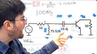
At 23:18 given is test circuit impedance looking through the gate side towards the input side terminated with 50 ohm resistor. The inductive reactance is that of the matching circuit, not the FET which is capacitive. Great series nonetheless. Gives excellent tutorial to amp builder beginner.
All impedances given in a data sheet are for the real part and imaginary part of the device measured from gate to gate and drain to drain (for a push - pull circuit) and do not include any test circuit impedances such as the input or output matching networks. With some devices, the imaginary part can change from inductive to capacitive as the frequency changes. Regards
I just found this video... Further more, your channel. Instant subscriber! Can't wait to learn from you! So, thank you in advance for sharing the knowledge and experience I am about to learn from you!
This is exactly what I was looking for. I am a ham who has been homebrewing. I have made a few low power amps with single IRF510s as the final. In one amp I am getting about 20W maximum from on IRF510 with a 20V power supply. One thing that I still don't quite understand is the impedance matching between the stages. I totally get that for the final to the antenna, you want the impedance matching to maximize power transfer. However, between the transistor stages, especially with the FETs, it seems that what matters is to impress the maximum voltage (like you mentioned it's a voltage device) from the earlier stage to the latter stage, and not the maximum power. In fact, if we were to match the previous stage to the next stage, the voltage from the previous stage would halve. I hope I am making sense. I will watch your other videos in this series and maybe i will have my answers!
Thanks for the excellent series on the IRF510 - Do you perhaps still have a copy of the printed material you used during this series? I'd like to build one of these and toy around with the circuit a little and having it in PDF would be really useful. Thanks!
Fantastic video RF Man with plenty of usefull information. I have seen all series again and again in order to adapt your way of thinking and desighn. Thanks for your efforts and will to explain in such depth. Few questions, Are both Mosfet N type as in drawing or one is P type. Do the mosfet source :see: real ground? or the entire pallet is lifted? In order to be excited how does the gate founds a ground in order to close circuit? Thanks again 73
Both transistor are N Channel. This is typical for a Push-Pull amplifier of this type. The source for each transistor is terminated to circuit (common) ground. The gate works with an electrostatic field to control the drain current. You can think of a MOSFET as a voltage controlled current source. RF Man
When designing these, I've always said there's a small bit of voodoo involved over stray inductance and capacitance over the layout. After doing the impedance calculations, the circuit should still be tuned, generally by a padder cap. You can get it close after the calculations, but layout and parts placement helps throw a wrench in the gears, so to speak.
Thanks for your feedback! To calculate the inductive reactance of the choke you need to measure the inductance and then apply the following formula: Xl = 2 x pi x F x L (Lis in Henry's). Regards
Loving your videos. The overview of the individual sections is quite easy to understand. Are you able to tell me where to look for LTSpice models of the LDMOS fets? I'd really like to model the circuit for better understanding. I hope you can help.
I have a question about being able to use the nanovna to adapt the output impedance of a BLF188 or any other power transistor. I could make a video. The one at the input seemed great. Greetings, I hope the video will be very helpful.
Looking at the PCB board it appears that it consists of two (2) separate independent boards; dedicated input side and dedicated output circuit side. Is that correct and if true please comment on purpose.
Hi RF Man. Thanks for these videos! I am seeking an RF amplifier that can input 250mw and boost to 3 watts+. Frequency range is 470-480mhz. Do you have any recommendations? Do you take on custom work? Thanks!
Since both IRF510s present a 50ohm impedance would that mean the transformer would see a 100ohm impedance or since they are 180 Degrees out of phase they present themselves as one at a time at 50 ohms total?
If someone wanted to build one of these amplifiers for the 160 m handbag, or lower, let's say one mhz. How would you calculate the input impedance. As it's not stated on the data sheet. A significantly lower frequency, I would assume it causes a gain increase in the f e t. But also the inductive capacitance would vary. So how would one actually calculate this?
Excellent video , any videos explaining the circuit's of RC toys Transmitter and receiver module's how the signals are transmitted from transmitter and receiver module of the RC toy to control the motor in the toy
Hello friend, where can I get these cores? I'm from Brazil, I search for which model on AliExpress, I would really like to learn and try to do this project, thank you very much!
Excellent! One thing that's always baffled me is how the input impedance of a MOSFET can be low (or appear to be low) for RF when its DC impedance is somewhere around 10MΩ. Is this because of the fairly high capacitance of the gate (about 150pF)? Related to that, of course, is the question of why we need preceding stages to boost _power_ to the drive the MOSFET when it responds to voltage rather than power (volts X amps).
trying to find information on building a power amp for sub 1Mhz like within 10khz-1Mhz.. doesnt have to be exactly within this range. if anyone can point me in the right direction, would be grateful thanks.
great series thank you please can you let me know where i can get a copy of the information sheets you used in the videos as i would like to learn more by experimentation thank you.
I have some problems!!! How rf power amplifier works I have a walkie talkie that have a rf power amplifier module inside and powered by 7.5v and have 5watts of power into the antenna How this is happening? We know our antenna have a impedance of 50 ohm so if: I = v÷r P= v × I I= 7.5v ÷ 50ohm=150mA P=7.5v×150mA=1.12 watts So why ican see 5watts in my power meter
If you watch my 6 part video series, you will have a better understanding of how an amplifier works. Basically An RF linear amplifier works by taking a low-power RF signal and amplifying it to a higher power level. The amplifier achieves this by using active devices such as transistors or vacuum tubes to amplify the signal.
@@rfmanchannel6915 thanks for answer. I have some modules from motorolla shw5066 they can produce 7watts of power with 7.5 volt battery and when I opened it ididnt see any transistor!!! I can send you some pictures of inside of it
I would focus on the supply. If its 7.5v at 1 amp then its 7.5w. Then x it by the efficiency of the device. A single transistor stage would be around 50% but your walkie probably uses a power block so it will be less. The 50 ohms is just the transmission line impedance and doesnt reflect on the spec of the device.
The thing is it’s no longer 7.5 volts when delivered to the 50 ohm antenna. Look at the current coming from your battery. Multiply it times the voltage of your battery. That’s how much DC power your radio is consuming. But, your radio turns that power into AC and modulates it before putting it on the antenna.


I've been struggling to understand the theory behind this for a long time, this has cleared up many things. Looking forward to watching the rest now, thank you!
Thanks for putting so much work into this video series. I'm halfway through no1 and really appreciate the circuit description. Looking forward to the remainder
Just came across these videos, as a young buck 21 years old I can’t explain how much these videos will help me, I’m a diesel mechanic by trade but have been into cb for 2 years and have been wanting to build my own ldmos amplifier. But the learning curve just in terminology has been huge for me to overcome
Excellent series on Push-Pull HF amplifier design process, well done RF Man. I can really appreciate your choice of the IRF510 as an early pioneer of its use as an RF amplifier. Mike Kossor, WA2EBY
Thanks for your feedback! RF Man
Looks like the non-engineer HAM class I've been looking for, thanks.
0:35: ⚙ Overview of designing a push-pull RF amplifier using IRF 510 MOSFET.
5:35: ⚙ Discussion on designing RF linear amplifier, including input and output board calculations and testing.
10:20: ⚙ Designing RF linear amplifiers involves reducing parasitic effects, increasing bandwidth, and ensuring gate bias and stability.
16:09: ⚙ Overview of RF linear amplifier operation classes and biasing techniques.
21:30: ⚡ Importance of impedance matching to prevent power reflection and transistor failure in RF amplifiers
⚙ Overview of designing a push-pull RF amplifier using IRF 510 MOSFET.
00:35
• Discusses the push-pull circuit topology and IRF 510 MOSFET usage.
00:35
• Focus on input and output boards design, with emphasis on cost-effective components.
00:42
• Emphasizes the affordability and historical usage of IRF 510 MOSFET for experimentation.
01:07
⚙ Discussion on designing RF linear amplifier, including input and output board calculations and testing.
05:35
• Calculation of output impedance, transformer ratios, and RF choke impedance.
05:35
• Bench testing for output power, gain, efficiency, SWR, harmonic distortion, and low-pass filter purpose.
06:10
⚙ Designing RF linear amplifiers involves reducing parasitic effects, increasing bandwidth, and ensuring gate bias and stability.
10:20
• Shunt resistor used to reduce parasitic effects and increase bandwidth of Transformer.
10:20
• Voltage divider with resistors, zener diodes, potentiometers, and chokes used for gate bias of mosfets.
10:57
• Mosfets are voltage devices with a threshold for current flow above a certain voltage level.
11:37
⚙ Overview of RF linear amplifier operation classes and biasing techniques.
16:09
• Class A and Class B operation offer higher linearity but lower efficiency.
16:09
• Class C operation provides higher efficiency but lower linearity.
16:38
• Biasing the transistor involves adjusting the gate voltage above the 4-volt threshold for optimal conduction.
17:07
⚡ Importance of impedance matching to prevent power reflection and transistor failure in RF amplifiers
21:30
• Increase in reflected power can cause excessive heating and transistor failure
21:30
• Impedance matching is crucial for both input and output sides to avoid thermal runaway
21:56
• Comparison of RF transistors like MRF 300 A/B and IRF 510 for push-pull applications
Recap by Tammy AI
beautiful channel for those who love RF
Thanks for your positive comments! RF Man
Really looking forward to this series! Thank you for spending the time creating!
Good stuff so far, I am looking forward to the next one.
FYI.....
When I was still in college I designed my first solid state amp...
Old school bipolar transistors. FETs have made this so much easier.
Can't wait for the next episode.
Yes, a agree! MOSFETs are much easier to bias and match....
Very good video. I like when you take your time discussing the process. I built irf510 amplifier, but it was rough journey.
This is a very well explained and produced video, thank-you. I shall watch the rest of the series now.
Thanks for your comments! RF Man
@@carminecampo2045 Thank-You, I watched the series and learnt a lot. I will be returning and watching again as a refresher from time to time.
Excellent video. Very clear and detailed explanation. Thank you so much for preparing the video and sharing your RF design knowledge.
I'm happy I can help!@ RF Man
At 23:18 given is test circuit impedance looking through the gate side towards the input side terminated with 50 ohm resistor. The inductive reactance is that of the matching circuit, not the FET which is capacitive. Great series nonetheless. Gives excellent tutorial to amp builder beginner.
All impedances given in a data sheet are for the real part and imaginary part of the device measured from gate to gate and drain to drain (for a push - pull circuit) and do not include any test circuit impedances such as the input or output matching networks. With some devices, the imaginary part can change from inductive to capacitive as the frequency changes. Regards
I just found this video... Further more, your channel. Instant subscriber! Can't wait to learn from you! So, thank you in advance for sharing the knowledge and experience I am about to learn from you!
Thanks for you comments! RF Man
Well I'm glad there's more to it because I was worried about getting all this in on video!
Look forward to this series !
This is exactly what I was looking for. I am a ham who has been homebrewing. I have made a few low power amps with single IRF510s as the final. In one amp I am getting about 20W maximum from on IRF510 with a 20V power supply. One thing that I still don't quite understand is the impedance matching between the stages. I totally get that for the final to the antenna, you want the impedance matching to maximize power transfer. However, between the transistor stages, especially with the FETs, it seems that what matters is to impress the maximum voltage (like you mentioned it's a voltage device) from the earlier stage to the latter stage, and not the maximum power. In fact, if we were to match the previous stage to the next stage, the voltage from the previous stage would halve. I hope I am making sense. I will watch your other videos in this series and maybe i will have my answers!
Yes, I understand your point. LTSpice is a good tool to learn and will help you measure impedance from stage to stage. RF Man
Fantastic, can't wait for part2 and more.
Thanks for the excellent series on the IRF510 - Do you perhaps still have a copy of the printed material you used during this series? I'd like to build one of these and toy around with the circuit a little and having it in PDF would be really useful. Thanks!
Fantastic video RF Man with plenty of usefull information. I have seen all series again and again in order to adapt your way of thinking and desighn. Thanks for your efforts and will to explain in such depth.
Few questions,
Are both Mosfet N type as in drawing or one is P type.
Do the mosfet source :see: real ground? or the entire pallet is lifted?
In order to be excited how does the gate founds a ground in order to close circuit?
Thanks again
73
Both transistor are N Channel. This is typical for a Push-Pull amplifier of this type. The source for each transistor is terminated to circuit (common) ground. The gate works with an electrostatic field to control the drain current. You can think of a MOSFET as a voltage controlled current source. RF Man
Wow I really like your video and is very interested
When designing these, I've always said there's a small bit of voodoo involved over stray inductance and capacitance over the layout. After doing the impedance calculations, the circuit should still be tuned, generally by a padder cap. You can get it close after the calculations, but layout and parts placement helps throw a wrench in the gears, so to speak.
Well explained 👌
one of the best tutorial on rf amplifier, please can you tell me the formular you used to calculate the value of 10 30uh rf chocke
Thanks for your feedback! To calculate the inductive reactance of the choke you need to measure the inductance and then apply the following formula: Xl = 2 x pi x F x L (Lis in Henry's). Regards
Loving your videos. The overview of the individual sections is quite easy to understand.
Are you able to tell me where to look for LTSpice models of the LDMOS fets? I'd really like to model the circuit for better understanding.
I hope you can help.
Thank you for this course 👍. Best 73's Chrisoph, HB9HAL
I have a question about being able to use the nanovna to adapt the output impedance of a BLF188 or any other power transistor. I could make a video. The one at the input seemed great. Greetings, I hope the video will be very helpful.
Looking at the PCB board it appears that it consists of two (2) separate independent boards; dedicated input side and dedicated output circuit side. Is that correct and if true please comment on purpose.
What are the changes needed for the 40m band?
I would like to see this done with the irfp260n
brilliant vid I learnt a lot of new info...thank you
Hi RF Man. Thanks for these videos! I am seeking an RF amplifier that can input 250mw and boost to 3 watts+. Frequency range is 470-480mhz. Do you have any recommendations? Do you take on custom work? Thanks!
excuse me sir for my ignorance but does it work with an analog TV VHF modulator?
Thank you in advance!
Since both IRF510s present a 50ohm impedance would that mean the transformer would see a 100ohm impedance or since they are 180 Degrees out of phase they present themselves as one at a time at 50 ohms total?
If someone wanted to build one of these amplifiers for the 160 m handbag, or lower, let's say one mhz. How would you calculate the input impedance. As it's not stated on the data sheet. A significantly lower frequency, I would assume it causes a gain increase in the f e t. But also the inductive capacitance would vary. So how would one actually calculate this?
Excellent video , any videos explaining the circuit's of RC toys
Transmitter and receiver module's how the signals are transmitted from transmitter and receiver module of the RC toy to control the motor in the toy
Sorry, I have no videos at the moment. I may post one next month discussing a 433MHz T/R module. Regards
Hello friend, where can I get these cores? I'm from Brazil, I search for which model on AliExpress, I would really like to learn and try to do this project, thank you very much!
Excellent work. What is the value of R5 used to reduce the quality factor and increase the bandwidth at the input ?
I used 60 ohms. Lower values will require a higher input drive level. Its a design tradeoff between drive level and impedance matching.
Thanks for your effort, superb learning material. Please keep up!
73, PA8MM
Thanks for your positive comments! RF Man
Great video series - thanks so much. Just what I have been looking for. Are the schematic and LtSpice files available for download? Dean, KK4DAS
Excellent! One thing that's always baffled me is how the input impedance of a MOSFET can be low (or appear to be low) for RF when its DC impedance is somewhere around 10MΩ. Is this because of the fairly high capacitance of the gate (about 150pF)? Related to that, of course, is the question of why we need preceding stages to boost _power_ to the drive the MOSFET when it responds to voltage rather than power (volts X amps).
trying to find information on building a power amp for sub 1Mhz like within 10khz-1Mhz.. doesnt have to be exactly within this range. if anyone can point me in the right direction, would be grateful thanks.
great series thank you please can you let me know where i can get a copy of the information sheets you used in the videos as i would like to learn more by experimentation thank you.
where you able to get the information sheets for this series?
I'd like them as well
Thank You & Count Me In !!!
73...
Fantastic! Thank you very much.
I have some problems!!!
How rf power amplifier works
I have a walkie talkie that have a rf power amplifier module inside and powered by 7.5v and have 5watts of power into the antenna
How this is happening?
We know our antenna have a impedance of 50 ohm so if:
I = v÷r
P= v × I
I= 7.5v ÷ 50ohm=150mA
P=7.5v×150mA=1.12 watts
So why ican see 5watts in my power meter
If you watch my 6 part video series, you will have a better understanding of how an amplifier works. Basically An RF linear amplifier works by taking a low-power RF signal and amplifying it to a higher power level. The amplifier achieves this by using active devices such as transistors or vacuum tubes to amplify the signal.
@@rfmanchannel6915 thanks for answer. I have some modules from motorolla shw5066 they can produce 7watts of power with 7.5 volt battery and when I opened it ididnt see any transistor!!! I can send you some pictures of inside of it
I would focus on the supply. If its 7.5v at 1 amp then its 7.5w. Then x it by the efficiency of the device. A single transistor stage would be around 50% but your walkie probably uses a power block so it will be less. The 50 ohms is just the transmission line impedance and doesnt reflect on the spec of the device.
The thing is it’s no longer 7.5 volts when delivered to the 50 ohm antenna.
Look at the current coming from your battery. Multiply it times the voltage of your battery. That’s how much DC power your radio is consuming. But, your radio turns that power into AC and modulates it before putting it on the antenna.
Thank you!
Thanks 👍
Great course
Oh my goodness imma eat this up
Hey Tom, I hope you are doing well! Thanks for your comments. RF Man
A two "pill" leanyer amplifier.
Promo-SM 😁
🌹🌹🌹🌸🌸🌸🌷🌷🌷
Qn826
Ĺinear
Yeah you clean your act up. You must went back and got another degree?
Muy buen trabajo, gracias por compartir, EA7KNH