I'm an intern working on 10G/40G backplanes and I can't tell you how much your videos mean to me. They just aren't teaching these kinds of things! I appreciate Eric's expertise, patience, and ability to explain simply. I also appreciate your questions throughout - it's almost like you read my mind with what I want to ask. Thank you!
For anyone wondering how the equation at @37:40 came up, it is elaborated below The base relation between Capacitance, charge and Voltage is C=q/V Re-arranging the equation with respect to V V=q/C Differentiating on both the sides, we get dV/dt = (1/C).(dq/dt) Since current I is the rate of flow of charges, I=(dq/dt), the above equation becomes, dV/dt = (1/C).(I) dV/dt = I/C The above equation is rearranged with respect to the parameter that needs to be calculated. In this video, we are calculating the capacitance. Hence, the equation becomes, C = (I.dt)/dV
I like where Mr. Bogatin points out that for the duration of di/dt, there exists a 1 V drop across the inductor, it teaches us to see and think differently!
I learned so much by watching this. I recently bought an oscilliscope just so I can see these things and this example is the exact experiement I bought the scope for. I'm here beause I recently built a circuit that runs from 9V 1.5A power supply that has an Arduino Nano, Small Servo, a small OLED screen, 5 various potentiometers, 5V opticouple relay which I'm using as the switch on an independent (brushed) motor driver board that I'm turning on/off that is being fed from 9V side of the power rail along with the motor. I'm using a L7805CV to power the 5V things (OLED, Servo, Relay) and the nano's getting it' power from the 9V side . . . I was having intermitent hangs in the whole system after running a while . . . I peeked with a probe and was astonished to see how the VR was spiking huge voltage spikes all over the place . . . I had NO capacitors other that what's called for in data sheets for the VR . . . So, learning about the need for placing capacitors throughout the board from various sources . . . I never came across the discussion of induction and WHY and this is the first time seeing this broken out so well. So, thank you . . . looking forward to learning more from the book. Also, I've purchased the book mentioned so I'm looking forward to receiving it and learning more.
These videos are always really good, they really nail down the things that you need to know without making it massively confusing or going on a wild goose chase to come to, the majority of the time, a very simple conclusion. I think its especially a difficult thing to do because knowing about something and teaching it are two seperate areas. I still do have to rewatch these videos a few times and takes notes but in a relatively short time (couple of hours) will come to a good understanding. Also props to Robert for asking the right questions and clarifying information either within the video, or doing a bit of editing to make it more obvious what is going on.
Another beautiful and insightful video! I Always appreciate Mr Bogatin's talks where he actually features theory with hands-on examples! Big thanks Robert for the video!
Very nice thanks to you, Eric and Robert! Keep in mind, we also often need to compromise for low-power devices that switch frequently in standby mode (resulting in loss to resupply the capacitor) or to limit the power supply for starting current (by increasing the regulator, for example, or accepting a longer starting time). Keep this in mind: if a 0.1µF capacitor does the job and the noise level is acceptable or has been tested as a good condition in the data sheet, then it is a minimum 'good' working condition and a correct one. This is not an optimum condition, but a good minimum for general use as a reference point in a data sheet. It is up to you to design electronics with a good understanding and thoughtful consideration including while you increase all decoupling capacitors and load the supply, that may now have new trouble.
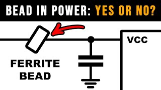
If you have excessive capacitance on the PCB for the power source at hand, just add an inductor in series with the power supply to reduce the burst current. Of course the slow rise of the input voltage can sometimes cause trouble with your reset logic, so that needs to be validated next for whether it's robust.
Great videos for practical PCB designers, the book he mentioned in the video is really good, it is really practical. Thanks for sharing these informative lectures !
This is actually a very widely used method to implement hardware/software hacking via glitching; the chip whisperer actually uses VCC rail Glitch Attacks so aside from the internal issues this phenomenon can cause it's actually important from a security aspect as well. Very well done guys.
This is such a very important video that was needed on Internet for electric engineering. Even if the contents could have been learned from your previous videos (the information was there), this one focuses on this problem and summarizes it perfectly. Thanks a lot, Robert!!
I do electronics repair and it's common enough to find an internally shorted capacitor on the PCB, and it's usually a high capacity MLCC, 10uF or so. I have doubts whether maximising capacitance on all your MLCCs is a good idea, they seem to get quite fragile, and the voltage rating margin is reduced as well. Furthermore if you're dealing with hot components, the local warpage of the PCB from thermal expansion is increased, so the closer in you bring such a capacitor to the IC, the more trouble it is. There is also some warpage in the capacitor itself from the voltage applied i think. I understand it's often a necessity, but maybe it's something to keep in mind, and maybe not introduce reliability hazards where they're not needed.
Eric's article was featured in the Embedded Muse about a year ago; a little while after I got an exam question which asked why a designer had used three capacitors each seperated by a decade... I pretended not to have read the piece ^^
also, what about the MLCC impedance vs frequency characteristic? the lower the capacitance, the higher the frequency at which the impedance is the lowest. should fast switching be considering high frequency in this context?
great warning on electrolytics, I always place something over the top of things when I power them on if it has electros, if I've just built it or recapped it.
@Eric: Thank you so much for this method of theory combined with demonstration. I have read The Myth of the Three Capacitors and it was a real eye-opener that gave me a kick that allowed me to shed a part of the legacy rust that held me down in my amateur circuit designs.
Great video. I was in the "0.1uF decoupling cap" gang until recently when I started playing with 1uF and 10uF smd caps and saw improvements. This did make me wonder why pretty much everything you read says to use 0.1uF decoupling caps. What you said about the inductance now makes sense.... Sort of. I'm a self taught hobbyist, so videos like this are invaluable for a better understanding. Thank you gents!
Thanks Robert and Eric , I watched the video twice,and ordered the Bogatin's Practical Guide to Prototype Breadboard and PCB Design,i think i need it.I also noticed the documentation named ECEN5730 lab manual that Eric showed in the video,I wonder if this document will ever be published.
Very informative video that makes it clear wht you should use care when selecting decoupling caps. I started out using tubes and fought my way through transistors and then IC's in my 30's and 40's. I was working on low power (
But how about those impedance curves for 1uF and 0.01uF capacitors that show that at frequencies above 1-10MHz you get a lower impedance and thus better decoupling with smaller capacitor values?
This is a good video for debunking the 3 cap myth, but I don't think I agree with the assessment of using as large a value as you can peppered around. If you pepper 10uF 0402s all over a board, you can quickly have 10 of them, once there's one for MCU, one for each i2c connected widget etc... So you have 100uF of ultra low impedance caps. Now on a modern board, you most likely have a switch mode or linear regulator locally supplying that 3v3/1.2/... rail, even the 9/12 is probably derived locally from a 24/48V rail by a several hundred kHz DCDC, and we probably have ground and power planes with near zero inductance. The local DCDCs at ...300..kHz do not drop out like the scope shots Eric made by a long way, and neither do locally referenced linear regs. So what is the dominant factor here really? I content that it is not the inductance or the capacitance; that is a 1990s problem and a bodged together breadboard problem. The real issue these days is regulator loop stability, and for that, we do not want to be driving a massive low impedance capacitor bank. So perhaps it is better to have a bulk with some ESR for stability and the localised low impedance capacitors are a much lower value... say we use a 100uF electrolytic or tantalum plus... 100nF 0402s. I contend that on a modern board, that will result in lower ripple and noise. Each DCDC/regulator and its control loop is a bit subtly different, but after many variations and attempts I have found that piling on high value low ESR ceramics is not the best choice.
So amazing content, well put and demonstrated with pratical application. Thank you both, Mr Feranec and Mr Bogatin, I would have loved to have such teachers, workbook and experiment during my engineering studies. It didn't stop me to become an electronics engineer but I really don't want to end-up writing App Notes with poor recommendations due to lack of understanding. Thank you for making this available for free and tackling this "legacy code" that no one was ever able to explain me. So valuable.
Am I right? Eric told to used 10uF 402 instead of 100nF? And it is safe? What about 1nF? OMG? But capacitance value interact with Self Resonant Frequency. And the SFR of 10uF is 100 time smaller than 100nF. How can it be? OMG! Maybe the point is, we dont care about capacitve or inductive behaviour at hf just need low impedance, we can synthesis that with multiple identical uF but that can produce huge inrush current! I Love you two guys. Thank you so much.
as DiodeGoneWild would say: "bloooody hellllll !!!!" - eye opening! Great workshop and that should be part of 121 of every electronic course! Thank you so much
Very important point: 1:00:50 Not many people actually think nowadays, and bury themselves in datasheets, etc. It's best to question everything. No matter what profession you're in, *trust but verify.*
Thank you Guys for you work and time. You are really doing brilliant work for all of us. I always watching with big pleasure you videos @Robert Feranec and want to say thank you 🙏.
I was wonder about the video and wanted to know more about that oscilloscope! Who is the manufacturer? and freq. Range! Your measurements are soooo amazing!!
i used a lot of tipical dip packaged opamps when i was indeed building audio gear. nice to have em in a socket, nice to try a few different opamps for testing how it sounds etc.. i had my opamps prepared by having local decoupling soldered directly on the leads as close to the package as possible. the cap it self was bang on the package it self. that very tipical 0.001 || 0.01 || 0.1 setup never made any sense nor did it ever sound well. i had indeed have this local decoupling and pair of larger value low inductance capacitor nearby in parllel.
Wow, I always blindly assumed that lower capacitance parts would always have lower inductance, even at the same package size. Guess I won't use 100nF caps as much anymore!
Very educational. Really simple example that fully demonstrates the purpose of decupling :) However... I was expecting one more chapter: how to place cap and vias relative to IC? I've seen many examples on the Internet: "via-cap-IC" or "cap-via-IC" or "cap-IC-via"...
Hi. Great video again! Thank both of you. Those bread board examples demonstrated these phenomenas way it was easy to understood what was happening there and what you were talking about.
Fantastic video! Thanks so much to both you and Eric for taking the time. Much of this is stuff that I've learned before, but I've been falling back into the trap of sprinkling 100nF everywhere like pixie dust, so I'm going to remind myself of Eric's words next time I'm working on a design.
Great video, but i have a question - what if capacitor is placed after the MOSFET in the south side of breadboard? We should place capacitors on the path between vrm and the load, or we should just add this additional "source" ?
What happened to the paperback version of Bogatin's Practical Guide that is shown at 36:48? It seems to have disappeared completely? You can't even find it by ISBN.
Good discussion. One of the issues I have is my old tools don't have much in way of calculators built-in and so calculating inductance of a trace isnt an option. I can put pads down and mess around with a scope like they've done in this vid but had hoped for a better approach. I guess at some point I'm gonna have to buy new s/w. I do like using through hole parts but more and more are smd and it is getting hard even for my hobby work to avoid
Really interesting stuff, thank you! Now how about when designing a LDMOS 440Mhz driver amp for let's say 5W output. Now every inductance counts, also for those decoupling capacitors. When using a single capacitor it will have a resonance frequency offering no decoupling at all near that frequency, often in the neigbourhood of a few 100 Mhz, that's why I still use those 3 values, 1nF, 10nF and 100nF on the powerrails., each having different resonant frequencies. I still think this is better solution than a single decoupling capacitor... What is your opinion about this? I hope to see an answer but looking at the other comments I guess I will not get one...
i was designed a analog board wile was listening the video, and start with one capacitors and change most of them at the end of the video. Always sospice at the 0.1uF ones but never take it off, now i did.
Thank you for your efforts. Robert and Eric. BTW, Eric, I was you 1kth subscriber on your YT channel. I took a video of the counter going up! Kudos and cheers!
I always enjoy these. It would have been interesting to hear Eric's thoughts on the idea that multiple capacitor values keeps the impedance curve lower across a wider frequency range, where the lowest impedance valley of each cap come at one frequency after another (I'll have to read his article). I'd also love to hear about avoiding resonances. Like we just made an LC circuit with the wire inductance and decoupling cap. When do we need to worry about that and consider damping? Many people suggest the use of Pi filters (CLC) in power distribution for generic noise filtering but I see some not using any damping. Is that okay? Is any amount of peaking at some frequency in an LC filter acceptable? Should I not use solely low ESR aluminum polymer caps because electrolyics are a guaranteed long term failure mode? What about a Pi filter with a ferrite instead of inductor?
Thanks Robert for the great video and Dr. Bogatin for sharing his huge knowledge on electronics. I wonder which model is the sick oscilloscope he's using 😂
Amazing video and content! I have a question regarding the switching here. How can we have NMOS for high-side switching with this configuration? Vgs threshold for IRF520 is ~4V so shouldn't the gate of the NMOS need 4V+9V to turn on?
It really isn't a question of the leads of the 1,000μF capacitor. You cut them as short as you like, but the construction of the electrolytic guarantees a significant inductance to render the electrolytic cap useless for decoupling fast changes. VC = It and we have C=1,000μF, I=400mA, t=50ns, so the voltage droop should be (400m x 50n)/1000μ = 20μV, but we observe about 800mV, and that equates to an effective capacitance of about 25nF at time-scales of tens of nanoseconds. The 1μF ceramic cap showed a droop of 600mV and that would be expected from a perfect capacitor of 33nF, so there's still a significant loss. You should have shown the effect of a quality 100nF cap, despite your misgivings. If you're happy with around 1V of switching spikes, then you only need a 22nF low-inductance capacitor with 400mA switching in 50ns. No wonder we use 100nF as standard close to each chip. It should not be confused with the decoupling capacitor used to prevent supply droop due to the internal resistance of the supply, and as you showed, that's a much lower frequency and requires a larger capacitor, but we don't need as many on a board because the inductances have relatively little effect on that. [Edit] It would have been helpful if you had actually shown the voltage at the source of the IRF520 to confirm the current, since its Vgs(th) is specified as between 2V and 4V, meaning that the actual current when the mosfet was turned on with 5V on the gate could be anywhere between
I literally just this morning put in my gerber to have boards made of a buck converter. I of course used 1206 caps... I wish I had watched this 5 hours earlier.
I'm getting the impression it's analogous to a water-hammer. When you turn on a tap, there's a reduction in pressure in the pipes, which, in old pipes can cause them to physically move as they relax. When the tap is turned back off, the pressure rises and there's a certain inertia in the water which can cause the pipes to bang on something as they physically move back under load. Not that electricity has an analogue for inertia, but voltage is often stated to be analogous to pressure. So the capacitor arrests the pressure spike, and reduces the "hammer". Would anyone agree with the general analogy?
I am little confused with explanation. First conclusion is : One should use 1uf instead of 0.1uf . My confusion is : One should use 1uf ceramic capacitor with 1000uf electrolyte capacitor ? 1000uf is too big , you haven't shown in experiment , what other values can be suitable like 10uf , 100uf ?
This is moreso for recreating ESR for a capacitor; some regulators were made before large capacity ceramic caps really existed... And due to how their control loops operate internally, having too little ESR on the output can cause it to become unstable and oscillate. So one method to get around that, is to add a series resistor to a ceramic cap!
Great video, but the self resonance of the SMD capacitor didn't come up. The question is: Aren't there cases where you want the higher resonant frequency of a smaller value capacitor, even though the package will have the same inductance as a larger value in the same package? My recollection is that the 0.1uF caps have a self resonance frequency at about 50 MHz while a 10uF capacitor's resonance might be between 5 and 10 MHz...
I believe the philosophy has always been bulk caps for higher current loadings, ceramics/film for filtration, both in case you have noise AND current draw. EEVBlog covers this in a video where you try to choose parts so that their self-resonance values align with the frequencies you want to filter.
Hi sir my name is vinod from hardware deparment in my company.i have a question for you that is, in our boards we are using a voltage regulators of part no:EN6347QI ,which is used to convert 5V to 3.3 and 1.5V.If one voltage regulator is shorted then we did not get any output at another voltage regulator of same part number but why it is so?????????????????????
Very interesting video, so much used and so often misunderstood. (Like the USB grounding of the shield haha, but before I start a war, back to caps 😂) Question 55:40 : put some whopping large caps for the powerrail, after for example the Vrm; this is sometimes maybe also a problem, with the big current rush in. A resistor is mandatory perhaps, but also reducing the ups like effect? What is the opinion of others?
Yep, low-resistance and relatively high-power resistor (if sized correctly it can also be a fuse/glitch resistor) can be used to limit inrush current. Chokes also help as well, they limit di/dt which affect the charging rate of the cap.
Now I have one question: it looks to me that the person doing the schematic does not have all the important information needed to calculate the decoupling (capacitor values, size, etc.). Isn't this a job that needs to be solved closely between the schematic designer and the PCB designer? How do companies work on this, when the roles are separated, or even 3rd partied?
I don't have this super expensive equipment to do that, but if needed and if I could, I would built a prototype and then measure it and tweak it. Also, some of these things can be simulated - so that would be another way to find out how the final schematic should look.
Feroelectric effect will make the larger values ceramic caps in physically smaller packages decline in effective capacity way lower than the nominal, -80% is not rare. 100n caps it is, still.
Hehehe I had two caps explode on me last week. First one went and I thought I'd reversed the thing, but when the second exploded I was scratching my head. After a little investigation my conclusion was that I should not put 16 volt caps on a 36 Volt rail!


I wish I had a teacher like Mr. Bogatin! It's so easy to follow even that complex materia. Thanks a lot both of you!
I'm an intern working on 10G/40G backplanes and I can't tell you how much your videos mean to me. They just aren't teaching these kinds of things!
I appreciate Eric's expertise, patience, and ability to explain simply. I also appreciate your questions throughout - it's almost like you read my mind with what I want to ask.
Thank you!
my feeling, exactly
For anyone wondering how the equation at @37:40 came up, it is elaborated below
The base relation between Capacitance, charge and Voltage is
C=q/V
Re-arranging the equation with respect to V
V=q/C
Differentiating on both the sides, we get
dV/dt = (1/C).(dq/dt)
Since current I is the rate of flow of charges, I=(dq/dt), the above equation becomes,
dV/dt = (1/C).(I)
dV/dt = I/C
The above equation is rearranged with respect to the parameter that needs to be calculated. In this video, we are calculating the capacitance.
Hence, the equation becomes,
C = (I.dt)/dV
I like where Mr. Bogatin points out that for the duration of di/dt, there exists a 1 V drop across the inductor, it teaches us to see and think differently!
I learned so much by watching this.
I recently bought an oscilliscope just so I can see these things and this example is the exact experiement I bought the scope for.
I'm here beause I recently built a circuit that runs from 9V 1.5A power supply that has an Arduino Nano, Small Servo, a small OLED screen, 5 various potentiometers, 5V opticouple relay which I'm using as the switch on an independent (brushed) motor driver board that I'm turning on/off that is being fed from 9V side of the power rail along with the motor.
I'm using a L7805CV to power the 5V things (OLED, Servo, Relay) and the nano's getting it' power from the 9V side . . .
I was having intermitent hangs in the whole system after running a while . . .
I peeked with a probe and was astonished to see how the VR was spiking huge voltage spikes all over the place . . .
I had NO capacitors other that what's called for in data sheets for the VR . . .
So, learning about the need for placing capacitors throughout the board from various sources . . . I never came across the discussion of induction and WHY and this is the first time seeing this broken out so well.
So, thank you . . . looking forward to learning more from the book. Also, I've purchased the book mentioned so I'm looking forward to receiving it and learning more.
These videos are always really good, they really nail down the things that you need to know without making it massively confusing or going on a wild goose chase to come to, the majority of the time, a very simple conclusion. I think its especially a difficult thing to do because knowing about something and teaching it are two seperate areas. I still do have to rewatch these videos a few times and takes notes but in a relatively short time (couple of hours) will come to a good understanding.
Also props to Robert for asking the right questions and clarifying information either within the video, or doing a bit of editing to make it more obvious what is going on.
Another beautiful and insightful video! I Always appreciate Mr Bogatin's talks where he actually features theory with hands-on examples! Big thanks Robert for the video!
Very nice thanks to you, Eric and Robert!
Keep in mind, we also often need to compromise for low-power devices that switch frequently in standby mode (resulting in loss to resupply the capacitor) or to limit the power supply for starting current (by increasing the regulator, for example, or accepting a longer starting time). Keep this in mind: if a 0.1µF capacitor does the job and the noise level is acceptable or has been tested as a good condition in the data sheet, then it is a minimum 'good' working condition and a correct one. This is not an optimum condition, but a good minimum for general use as a reference point in a data sheet. It is up to you to design electronics with a good understanding and thoughtful consideration including while you increase all decoupling capacitors and load the supply, that may now have new trouble.
If you have excessive capacitance on the PCB for the power source at hand, just add an inductor in series with the power supply to reduce the burst current.
Of course the slow rise of the input voltage can sometimes cause trouble with your reset logic, so that needs to be validated next for whether it's robust.
Man your videos are a gift. Working with hardware became much easier with your tutorials. Cheers Robert!
Great videos for practical PCB designers, the book he mentioned in the video is really good, it is really practical. Thanks for sharing these informative lectures !
This is actually a very widely used method to implement hardware/software hacking via glitching; the chip whisperer actually uses VCC rail Glitch Attacks so aside from the internal issues this phenomenon can cause it's actually important from a security aspect as well. Very well done guys.
Do you know someone who could talk about this? I could try to contact them ... and maybe make a video about it.
@@RobertFeranec Stacksmashing did a video on using voltage drop to enable jtag on an airtag to dump its firmware
would be interested to know more without going on a deep dive with my substandard internet service (
This is such a very important video that was needed on Internet for electric engineering. Even if the contents could have been learned from your previous videos (the information was there), this one focuses on this problem and summarizes it perfectly. Thanks a lot, Robert!!
I like the 50:03 part discussion on bulk capacitors. The bulk capacitors help slow transients due to output resistance, after the fast edge.
A brilliant explanation empowered as with theory and as well proved practically that`s how the education giving should look like
This video is full of great information, full of useful things I can put into practice right away. And, I need a better scope. 😀
8:50 This part right here cleared a lot of my confusion regarding this topic. Great video,
I do electronics repair and it's common enough to find an internally shorted capacitor on the PCB, and it's usually a high capacity MLCC, 10uF or so. I have doubts whether maximising capacitance on all your MLCCs is a good idea, they seem to get quite fragile, and the voltage rating margin is reduced as well. Furthermore if you're dealing with hot components, the local warpage of the PCB from thermal expansion is increased, so the closer in you bring such a capacitor to the IC, the more trouble it is. There is also some warpage in the capacitor itself from the voltage applied i think. I understand it's often a necessity, but maybe it's something to keep in mind, and maybe not introduce reliability hazards where they're not needed.
Eric's article was featured in the Embedded Muse about a year ago; a little while after I got an exam question which asked why a designer had used three capacitors each seperated by a decade... I pretended not to have read the piece ^^
also, what about the MLCC impedance vs frequency characteristic? the lower the capacitance, the higher the frequency at which the impedance is the lowest. should fast switching be considering high frequency in this context?
great warning on electrolytics, I always place something over the top of things when I power them on if it has electros, if I've just built it or recapped it.
@Eric: Thank you so much for this method of theory combined with demonstration. I have read The Myth of the Three Capacitors and it was a real eye-opener that gave me a kick that allowed me to shed a part of the legacy rust that held me down in my amateur circuit designs.
Great video.
I was in the "0.1uF decoupling cap" gang until recently when I started playing with 1uF and 10uF smd caps and saw improvements. This did make me wonder why pretty much everything you read says to use 0.1uF decoupling caps.
What you said about the inductance now makes sense.... Sort of.
I'm a self taught hobbyist, so videos like this are invaluable for a better understanding.
Thank you gents!
Thanks Robert and Eric , I watched the video twice,and ordered the Bogatin's Practical Guide to Prototype Breadboard and PCB Design,i think i need it.I also noticed the documentation named ECEN5730 lab manual that Eric showed in the video,I wonder if this document will ever be published.
Very informative video that makes it clear wht you should use care when selecting decoupling caps.
I started out using tubes and fought my way through transistors and then IC's in my 30's and 40's. I was working on low power (
But how about those impedance curves for 1uF and 0.01uF capacitors that show that at frequencies above 1-10MHz you get a lower impedance and thus better decoupling with smaller capacitor values?
Isn't than answered at minute 1:01:40? Or do you mean something else?
This is a good video for debunking the 3 cap myth, but I don't think I agree with the assessment of using as large a value as you can peppered around. If you pepper 10uF 0402s all over a board, you can quickly have 10 of them, once there's one for MCU, one for each i2c connected widget etc... So you have 100uF of ultra low impedance caps. Now on a modern board, you most likely have a switch mode or linear regulator locally supplying that 3v3/1.2/... rail, even the 9/12 is probably derived locally from a 24/48V rail by a several hundred kHz DCDC, and we probably have ground and power planes with near zero inductance.
The local DCDCs at ...300..kHz do not drop out like the scope shots Eric made by a long way, and neither do locally referenced linear regs.
So what is the dominant factor here really? I content that it is not the inductance or the capacitance; that is a 1990s problem and a bodged together breadboard problem. The real issue these days is regulator loop stability, and for that, we do not want to be driving a massive low impedance capacitor bank. So perhaps it is better to have a bulk with some ESR for stability and the localised low impedance capacitors are a much lower value... say we use a 100uF electrolytic or tantalum plus... 100nF 0402s. I contend that on a modern board, that will result in lower ripple and noise. Each DCDC/regulator and its control loop is a bit subtly different, but after many variations and attempts I have found that piling on high value low ESR ceramics is not the best choice.
So amazing content, well put and demonstrated with pratical application.
Thank you both, Mr Feranec and Mr Bogatin, I would have loved to have such teachers, workbook and experiment during my engineering studies.
It didn't stop me to become an electronics engineer but I really don't want to end-up writing App Notes with poor recommendations due to lack of understanding.
Thank you for making this available for free and tackling this "legacy code" that no one was ever able to explain me. So valuable.
Thanks so much Professor Bogatin!
Very long. But well worth viewing the entire video. Good detailed explanations. Thank you sincerely.
Robert! Could you speak about industrial embedded hardware design?
Am I right? Eric told to used 10uF 402 instead of 100nF? And it is safe? What about 1nF? OMG? But capacitance value interact with Self Resonant Frequency. And the SFR of 10uF is 100 time smaller than 100nF. How can it be? OMG! Maybe the point is, we dont care about capacitve or inductive behaviour at hf just need low impedance, we can synthesis that with multiple identical uF but that can produce huge inrush current!
I Love you two guys. Thank you so much.
as DiodeGoneWild would say: "bloooody hellllll !!!!" - eye opening! Great workshop and that should be part of 121 of every electronic course! Thank you so much
Very important point: 1:00:50
Not many people actually think nowadays, and bury themselves in datasheets, etc. It's best to question everything. No matter what profession you're in, *trust but verify.*
Thank you Guys for you work and time. You are really doing brilliant work for all of us. I always watching with big pleasure you videos @Robert Feranec and want to say thank you 🙏.
why on earth does this video not having least a billion views ? real life proof that life ain't fair.
Thanks Prof Bogatin and Robert! What a great explanation.
Awesome interview. Just found it now. Excellent explanation by Eric.
New subscriber here. Wish I had a teacher like Mr. Eric.. this is really well explained. Please continue to make more like this awesome video.
I was wonder about the video and wanted to know more about that oscilloscope! Who is the manufacturer? and freq. Range! Your measurements are soooo amazing!!
Is there a source to get the lab document shown here? The workbook seen in the beginning?
Thank you very much Professor Eric and Robert. I learned many things I can use.
Robert and Erik, what a great combo. Thanks a lot for this fantastic video.
i used a lot of tipical dip packaged opamps when i was indeed building audio gear. nice to have em in a socket, nice to try a few different opamps for testing how it sounds etc.. i had my opamps prepared by having local decoupling soldered directly on the leads as close to the package as possible. the cap it self was bang on the package it self. that very tipical 0.001 || 0.01 || 0.1 setup never made any sense nor did it ever sound well. i had indeed have this local decoupling and pair of larger value low inductance capacitor nearby in parllel.
Great video gents
Wow, I always blindly assumed that lower capacitance parts would always have lower inductance, even at the same package size. Guess I won't use 100nF caps as much anymore!
Very educational. Really simple example that fully demonstrates the purpose of decupling :)
However... I was expecting one more chapter: how to place cap and vias relative to IC? I've seen many examples on the Internet: "via-cap-IC" or "cap-via-IC" or "cap-IC-via"...
Clear and brilliant , as usually BTW 😀 Great job and thanks a lot to both of you!
You are good at this Robert.Thanks.
Hi. Great video again! Thank both of you. Those bread board examples demonstrated these phenomenas way it was easy to understood what was happening there and what you were talking about.
Well, if that didn't clear it up for me, I don't know what will. Thanks for the awesome Vid Robert.
Superb video. The only thing that would've made it better is having Eric blow that big cap at the end 😇
One more thing, when the gate drive turns off the power rail will overshoot… and maybe goes out of spec of connected devices..
That is incredible! Thank you very much for sharing. I learned ALOT.
Great video Robert, can we also get a PDF copy link for the documents shared in the meeting?
Your channel is a wealth of information
It was an amazing video! Thank you both Eric and Robert!
Fantastic video! Thanks so much to both you and Eric for taking the time. Much of this is stuff that I've learned before, but I've been falling back into the trap of sprinkling 100nF everywhere like pixie dust, so I'm going to remind myself of Eric's words next time I'm working on a design.
Thank you so much for videos with Eric, everytime this is very interesting!
Great video, but i have a question - what if capacitor is placed after the MOSFET in the south side of breadboard? We should place capacitors on the path between vrm and the load, or we should just add this additional "source" ?
Thanks. I love your deep dive videos. Knowing that you should do it is nice. But I want to understand why :D
Phenomenal video as usual. Thanks for this, both of you guys!
Thank you both of you Sir.......... very good explanation
Very helpful. thank you both :)
What happened to the paperback version of Bogatin's Practical Guide that is shown at 36:48? It seems to have disappeared completely? You can't even find it by ISBN.
Good discussion. One of the issues I have is my old tools don't have much in way of calculators built-in and so calculating inductance of a trace isnt an option. I can put pads down and mess around with a scope like they've done in this vid but had hoped for a better approach. I guess at some point I'm gonna have to buy new s/w. I do like using through hole parts but more and more are smd and it is getting hard even for my hobby work to avoid
Really interesting stuff, thank you! Now how about when designing a LDMOS 440Mhz driver amp for let's say 5W output. Now every inductance counts, also for those decoupling capacitors. When using a single capacitor it will have a resonance frequency offering no decoupling at all near that frequency, often in the neigbourhood of a few 100 Mhz, that's why I still use those 3 values, 1nF, 10nF and 100nF on the powerrails., each having different resonant frequencies. I still think this is better solution than a single decoupling capacitor... What is your opinion about this? I hope to see an answer but looking at the other comments I guess I will not get one...
i was designed a analog board wile was listening the video, and start with one capacitors and change most of them at the end of the video.
Always sospice at the 0.1uF ones but never take it off, now i did.
Thank you for your efforts. Robert and Eric. BTW, Eric, I was you 1kth subscriber on your YT channel. I took a video of the counter going up! Kudos and cheers!
37:54 I'm confused, given this formula, you can use smaller capacitance with lower rising time?
OMG that is THE Explanation!
I always enjoy these. It would have been interesting to hear Eric's thoughts on the idea that multiple capacitor values keeps the impedance curve lower across a wider frequency range, where the lowest impedance valley of each cap come at one frequency after another (I'll have to read his article). I'd also love to hear about avoiding resonances. Like we just made an LC circuit with the wire inductance and decoupling cap. When do we need to worry about that and consider damping? Many people suggest the use of Pi filters (CLC) in power distribution for generic noise filtering but I see some not using any damping. Is that okay? Is any amount of peaking at some frequency in an LC filter acceptable? Should I not use solely low ESR aluminum polymer caps because electrolyics are a guaranteed long term failure mode? What about a Pi filter with a ferrite instead of inductor?
thank you. have you seen this video? th-cam.com/video/hZSOhVdzqZk/w-d-xo.html
@@RobertFeranec I'm not sure I have. I'll have to watch that whole series!
We have been using tantalum caps along with ceramic for supply decoupling for many decades for precisely this reason.
Thanks Robert for the great video and Dr. Bogatin for sharing his huge knowledge on electronics. I wonder which model is the sick oscilloscope he's using 😂
Great video! Thanks you both for this content is really interesting!
Awesowm explanation and video. I would love to buy Erics book but it is 150-200€ at the moment....damn...
Nice , great explanation
What PC app is used to create the course ? Visible around 20:50. Is it some variant of MS WORD ?
Amazing video and content! I have a question regarding the switching here. How can we have NMOS for high-side switching with this configuration? Vgs threshold for IRF520 is ~4V so shouldn't the gate of the NMOS need 4V+9V to turn on?
I exactly searched for that now, and see that video uploaded 1 hour ago lol
:D
great material thanks you both!
It really isn't a question of the leads of the 1,000μF capacitor. You cut them as short as you like, but the construction of the electrolytic guarantees a significant inductance to render the electrolytic cap useless for decoupling fast changes. VC = It and we have C=1,000μF, I=400mA, t=50ns, so the voltage droop should be (400m x 50n)/1000μ = 20μV, but we observe about 800mV, and that equates to an effective capacitance of about 25nF at time-scales of tens of nanoseconds. The 1μF ceramic cap showed a droop of 600mV and that would be expected from a perfect capacitor of 33nF, so there's still a significant loss. You should have shown the effect of a quality 100nF cap, despite your misgivings.
If you're happy with around 1V of switching spikes, then you only need a 22nF low-inductance capacitor with 400mA switching in 50ns. No wonder we use 100nF as standard close to each chip. It should not be confused with the decoupling capacitor used to prevent supply droop due to the internal resistance of the supply, and as you showed, that's a much lower frequency and requires a larger capacitor, but we don't need as many on a board because the inductances have relatively little effect on that.
[Edit] It would have been helpful if you had actually shown the voltage at the source of the IRF520 to confirm the current, since its Vgs(th) is specified as between 2V and 4V, meaning that the actual current when the mosfet was turned on with 5V on the gate could be anywhere between
I literally just this morning put in my gerber to have boards made of a buck converter. I of course used 1206 caps... I wish I had watched this 5 hours earlier.
Mr. Eric this is legendary video. How can i be your student? :) i am 38 years old but still a student and will be a student for ever :)
Thank you.
@ 26:00 or so Where does he get the current of 400mA from when calculating the source resistance?
I'm getting the impression it's analogous to a water-hammer.
When you turn on a tap, there's a reduction in pressure in the pipes, which, in old pipes can cause them to physically move as they relax.
When the tap is turned back off, the pressure rises and there's a certain inertia in the water which can cause the pipes to bang on something as they physically move back under load.
Not that electricity has an analogue for inertia, but voltage is often stated to be analogous to pressure.
So the capacitor arrests the pressure spike, and reduces the "hammer".
Would anyone agree with the general analogy?
I am little confused with explanation.
First conclusion is : One should use 1uf instead of 0.1uf .
My confusion is : One should use 1uf ceramic capacitor with 1000uf electrolyte capacitor ?
1000uf is too big , you haven't shown in experiment , what other values can be suitable like 10uf , 100uf ?
Great video. When we are discussing myths in some applications are suggested to put a series resistor at the capacitor, is this also unnecessary?
This is moreso for recreating ESR for a capacitor; some regulators were made before large capacity ceramic caps really existed... And due to how their control loops operate internally, having too little ESR on the output can cause it to become unstable and oscillate. So one method to get around that, is to add a series resistor to a ceramic cap!
I love your videos
Great video, but the self resonance of the SMD capacitor didn't come up. The question is: Aren't there cases where you want the higher resonant frequency of a smaller value capacitor, even though the package will have the same inductance as a larger value in the same package? My recollection is that the 0.1uF caps have a self resonance frequency at about 50 MHz while a 10uF capacitor's resonance might be between 5 and 10 MHz...
I believe the philosophy has always been bulk caps for higher current loadings, ceramics/film for filtration, both in case you have noise AND current draw. EEVBlog covers this in a video where you try to choose parts so that their self-resonance values align with the frequencies you want to filter.
Hi sir my name is vinod from hardware deparment in my company.i have a question for you that is, in our boards we are using a voltage regulators of part no:EN6347QI ,which is used to convert 5V to 3.3 and 1.5V.If one voltage regulator is shorted then we did not get any output at another voltage regulator of same part number but why it is so?????????????????????
awesome video! thank you so much!
Just place 100nF everywhere, it'll be fine.
And maybe read the datasheet to see if they recommend values and layout.
Amazing content. Keep it up.
Very interesting video, so much used and so often misunderstood. (Like the USB grounding of the shield haha, but before I start a war, back to caps 😂)
Question 55:40 : put some whopping large caps for the powerrail, after for example the Vrm; this is sometimes maybe also a problem, with the big current rush in. A resistor is mandatory perhaps, but also reducing the ups like effect? What is the opinion of others?
Yep, low-resistance and relatively high-power resistor (if sized correctly it can also be a fuse/glitch resistor) can be used to limit inrush current. Chokes also help as well, they limit di/dt which affect the charging rate of the cap.
Now I have one question: it looks to me that the person doing the schematic does not have all the important information needed to calculate the decoupling (capacitor values, size, etc.). Isn't this a job that needs to be solved closely between the schematic designer and the PCB designer? How do companies work on this, when the roles are separated, or even 3rd partied?
I don't have this super expensive equipment to do that, but if needed and if I could, I would built a prototype and then measure it and tweak it. Also, some of these things can be simulated - so that would be another way to find out how the final schematic should look.
Feroelectric effect will make the larger values ceramic caps in physically smaller packages decline in effective capacity way lower than the nominal, -80% is not rare. 100n caps it is, still.
Hehehe I had two caps explode on me last week. First one went and I thought I'd reversed the thing, but when the second exploded I was scratching my head.
After a little investigation my conclusion was that I should not put 16 volt caps on a 36 Volt rail!
very usefull video! THANKS!!!!!!
Amazing video
Can you imagine listening to a textbook instead of Eric when he gives explanations like this? 😂
I'd love to see this done with an X2Y capacitor like EMCP100W104M1GV001T