PLC Hydraulic Press Logic - Anti Tie Down Ladder Logic Programming

ฝัง
- เผยแพร่เมื่อ 17 ส.ค. 2022
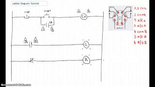
- In this video, you will learn the PLC hydraulic press logic and it is also called as Anti tie down ladder logic programming concept.
Free PLC and SCADA Training Courses ##
1. Free Siemens PLC Training Course
instrumentationtools.com/siem...
2. Free Allen Bradley PLC Ladder Logic Training Course
instrumentationtools.com/free...
3. Free InTouch SCADA Tutorial Course for Beginners
instrumentationtools.com/into...
4. Free WinCC SCADA Training Course
instrumentationtools.com/scad...
hydraulic press machine,plc,plc programming,ladder logic,plc training,ladder logic basics,learn plc programming,plc training course,hydraulic press,two hand logic,anti tie down logic,plc hydraulic press,hydraulic press plc programming,hydraulic press plc,plc two hand logic,hydraulic press machine manufacturer,press,press machine,hydraulic press machine price,delta plc programming,plc example,plc prgramming example,plc basics,hydraulic bearing press
#PLC #hydraulicpress #ladderlogic


=> Watch Next Video - HMI Programming of Hydraulic Press
th-cam.com/video/pPlK__NezrA/w-d-xo.html
=> PLC and SCADA Courses
learn.automationcommunity.com/courses/
Good clarity in explanation. Thanks brother
VERY VERY HELPFUL THANKS
Very good session 👍
Sir these video is very helpful.. thank you sir for this video please upload more videos like this it's a humble request to you
Sure
@@InstrumentationTools Dear Instrumentation Tool
Kindly check your's program in below given
In this process:-
1st rung:-
pb start NO, pb stop NC, Emg NC then M0
latch M0 to Emg NC
2nd rung:-
pb1 NO or, pb2 NO, M0 then M1
latch M1 to pb2 NO
3rd rung:-
M1 NO then output oil pump ON
4th rung:-
pb1 NO, M1 NO then TMR T0 say, 20 secs, memory M2
latch M2 to M1
pb2 NO, M2 NO then TMR T1 say, 20 secs, memory M3
latch M3 to M2
The Next Rungs I will design will be for the Tie Up Program Logic.
The program you made till 1st & 2nd rung, somehow, it will work.
But, in 3rd rung you made TMR T0 for 5 secs
in 4th rung T0 is NC & it will reset within 5 secs, the output down valve Y1
you need not reset Y1 in 5th rung.
That means before the process variable reaches down sensor X2, your's Y1 will de-activate by TMR T0.
I have seen you didnot latch the pb start, pb stop, emergency pb push buttons, pb1 & pb2
Even you didnot simulate & showed it to us
If you want to learn the correct Tie Up logic & the whole process, kindly respond back
Thanking you so much
great dear sir
Nice sir ,,, please Make a video on Lubrication tank logic with digital timer
Gracias
best video
J
Software download link send
Here:
th-cam.com/video/kBXodt3ac6Y/w-d-xo.html&pp=gAQBiAQB
Dear Instrumentation Tool
Kindly check your's program in below given
In this process:-
1st rung:-
pb start NO, pb stop NC, Emg NC then M0
latch M0 to Emg NC
2nd rung:-
pb1 NO or, pb2 NO, M0 then M1
latch M1 to pb2 NO
3rd rung:-
M1 NO then output oil pump ON
4th rung:-
pb1 NO, M1 NO then TMR T0 say, 20 secs, memory M2
latch M2 to M1
pb2 NO, M2 NO then TMR T1 say, 20 secs, memory M3
latch M3 to M2
The Next Rungs I will design will be for the Tie Up Program Logic.
The program you made till 1st & 2nd rung, somehow, it will work.
But, in 3rd rung you made TMR T0 for 5 secs
in 4th rung T0 is NC & it will reset within 5 secs, the output down valve Y1
you need not reset Y1 in 5th rung.
That means before the process variable reaches down sensor X2, your's Y1 will de-activate by TMR T0.
I have seen you didnot latch the pb start, pb stop, emergency pb push buttons, pb1 & pb2
Even you didnot simulate & showed it to us
If you want to learn the correct Tie Up logic & the whole process, kindly respond back
Thanking you so much
Respected sir,
Thanks for asking
First let me tell you my logic if both pb1 and pb2 before timer NC bit becomes off then we have used set Y1
So now coming to your doubt Y1 does not become off even if timer NC resets because we have used set operation
Second doubt why we reseted Y1 in 5rd rung because as I said we have used set Y1 in 4th so we need to reset when it reaches down sensor
And last thing you asked for simulation so we do simulation in all our examples in 2nd part of each topic after HMI designing so please watch that video for simulation.
Simulation Video Link:
th-cam.com/video/pPlK__NezrA/w-d-xo.html
@@yashwadhwani2002 Dear Yash
The concept Anti Tie is very important topic.
Now, please understand Anti Tie between 2 or more push buttons,
for eg.: Take the process for, pb1 & pb2:-
Process:-
When pb1 & pb2 pressed together simultaneously, load l1 gets ON.
pb1 & pb2 can have a time delay difference of say, 20 secs ( zooming time delay till 20 secs, to understand )
Program:-
1st rung: pb1 NO to memory M0,
latch M0 to pb1
2nd rung: M0 NO to TMR T0 ( 40 secs )
3rd rung: pb2 NO to memory M1,
latch M1 to pb2
4th rung: M1 NO to TMR T1 ( 40 secs )
The next rungs I will explain if you have the patience to learn till this.
Now, in your's program:-
In 2nd rung:
you activated TMR T0 for 5 secs
In 3rd rung:
pb1 & pb2 in AND GATE & TMR T0 is NC to valve Y1
In 4th rung:
down sensor X2 will ON, then Y1 will reset, Y2 set
But, the process will not work,
the hydralic press will not reach till down sensor X2, because within 5 secs, in 3rd rung, the Y1 might get reset.
The hydralic press might hang between X1 & X2
Next, there is no Anti Tie program made between pb1 & pb2, you just made a AND GATE
Kindly, read this full message.
Because the Anti Tie between pb1 & pb2 is itself a big process & program with multiple rungs
Thanks for your's initiative & response
Regards